Sommaire des Matières pour Varian TV 141
- Page 1 MANUALE ISTRUZIONI TV 141 Navigator BEDIENUNGSHANDBUCH Vent Valve NOTICE DE MODE D’EMPLOI INSTRUCTION MANUAL Model 969-9834 87-900-911-01 (C) APRIL 2002...
- Page 2 TV 141 Navigator Vent Valve...
- Page 5 PROCEDURA PER L’INSTALLAZIONE ................ ANLEITUNG ZUR INSTALLATION ................PROCÉDURE POUR L’INSTALLATION ............... INSTALLATION PROCEDURE ..................
-
Page 6: Caratteristiche Tecniche
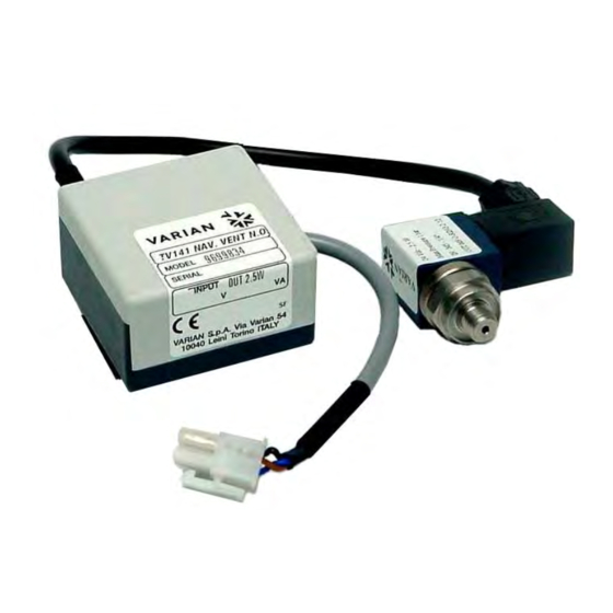
PROCEDURA PER L’INSTALLAZIONE PROCEDURA PER L’INSTALLAZIONE DEL KIT TV 141 NAVIGATOR VENT VALVE Vent valve GENERALITÀ • Stato valvola Normalmente aperta Il kit “TV 141 Navigator Vent Valve” comprende un’unità (chiusa quando viene di controllo ed una valvola, che realizzano un sistema... - Page 7 PROCEDURA PER L’INSTALLAZIONE INSTALLAZIONE In figura sono riportati i vari componenti presenti nel Kit TV 141 Navigator Vent Valve. Tali componenti sono forniti disassemblati; sarà quindi cura del cliente provvedere all’assemblaggio del Kit. Adattatore Filtro aria O-ring Valvola Cavo Valvola-Controller Valvola/bobina Unità...
-
Page 8: Technische Daten
ANLEITUNG ZUR INSTALLATION DER BAUGRUPPE TV 14 NAVIGATOR VENT VALVE ALLGEMEINES Vent valve • Ventilzustand Normalerweise offen Die Baugruppe “TV 141 Navigator Vent Valve” umfaßt (bei Versorgung eine Steuereinheit und ein Ventil, die ein komplettes geschlossen) System zur automatischen Belüftung der Pumpe beim •... - Page 9 ANLEITUNG ZUR INSTALLATION INSTALLATION In der Abbildung sind die verschiedenen Bauteile der Baugruppe TV 141 Navigator Vent Valve dargestellt. Diese Bauteile werden lose geliefert und müssen daher vom Kunden zusammengebaut werden. Adapter Luftfilter O-ring Ventil Ventil/Spule Ventilüberwachungskabel Überwachungs- einheit Ausgangssteckverbinder Anschlußkabel Überwachungseinheit/...
-
Page 10: Généralités
PROCÉDURE POUR L’INSTALLATION PROCÉDURE POUR L’INSTALLATION DU KIT TV 141 NAVIGATOR VENT VALVE GÉNÉRALITÉS Vent Valve • Etat de la valve Normalement ouverte Le kit “TV 141 Navigator Vent Valve” est composé (fermée lorsqu’elle d’une unité de commande et d’une valve qui forment un est alimentée) - Page 11 PROCÉDURE POUR L’INSTALLATION INSTALLATION Les éléments composant le kit TV 141 Navigator Vent Valve sont illustrés sur la figure ci-après. Ces éléments sont livrés désassemblés; par conséquent le client devra effectuer l’assemblage du kit. Adaptateur Filtre à air Joint torique...
-
Page 12: Technical Characteristics
Vent valve • Valve status Normally open The “TV 141 Navigator Vent Valve” kit, consisting of a (closed when power is control unit and valve, is a complete unit for automatic applied) pump venting when the pump is switched off or during •... - Page 13 INSTALLATION PROCEDURE INSTALLATION The following figure shows the various components of Navigator Vent Valve kit. These components come disassembled and it is therefore up to the customer to assemble the kit. Adapter Air filter Valve O-ring Valve-controller cable Valve/coil Control unit Output connector Control unit pump controller connection cable...
-
Page 14: Customer Information
NOTE: If a product is received at Varian which is contaminated with a toxic or hazardous material that was not disclosed, the customer will be held responsible for all costs incurred to ensure the safe handling of the product, and is liable for any harm or injury to Varian employees as well as to any third party occurring as a result of exposure to toxic or hazardous materials present in the product. - Page 15 Request for Return FAILURE REPORT TURBO PUMPS and TURBOCONTROLLERS POSITION PARAMETERS Power: Rotational Speed: Does not start Noise Vertical Current: Inlet Pressure: Does not spin freely Vibrations Horizontal Temp 1: Foreline Pressure: Does not reach full speed Leak Upside-down Mechanical Contact Overtemperature Other: Temp 2:...
- Page 16 Tel: (39) 011 997 9111 Tel: (39) 011 997 9111 Fax: (39) 011 997 9350 Brazil Fax: (39) 011 997 9350 Varian Industria e Comercio Ltda. Japan Avenida Dr. Cardoso de Mello 1644 Internet Users: Varian Vacuum Technologies Vila Olimpia Customer Service &...


