
Manuels Connexes pour Mychef mychill TCHA03TG

Sommaire des Matières pour Mychef mychill TCHA03TG
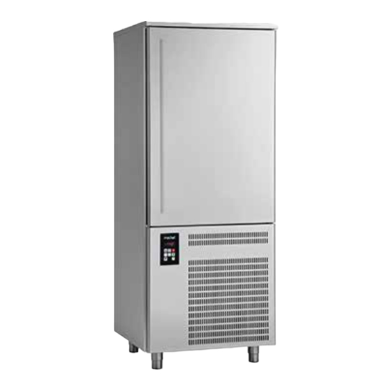
- Page 1 3/5/10/15 TRAYS BLAST CHILLER ABATIDOR 3/5/10/15 BANDEJAS CELLULE DE REFROIDISSEMENT 3/5/10/15 BACS Instructions for use Instrucciones de uso Mode d’emploi...
- Page 2 pag. 2...
-
Page 3: Table Des Matières
1 – GENERAL INFORMATION ............................8 1.1 – MARKING ................................8 1.2 – DECLARATION OF CONFORMITY ........................9 1.3 – WARRANTY ................................ 10 1.4 – AFTER-SALES SERVICE ........................... 10 1.5 – HOW TO USE AND KEEP THE MANUAL ......................10 1.5.1 –... - Page 4 7.8 – HARD CHILLING ..............................34 7.8.1 – SELECTING AND SETTING OF HARD CHILLING CYCLE ..............34 7.9 –FREEZING ................................35 7.9.1– SELECTING AND SETTING OF FREEZING CYCLE ................35 7.10 –SPECIAL USES ..............................36 7.10.1 – PRE-CHILLING FUNCTION OR CONTINUOUS CYCLE................36 7.10.2 –...
- Page 5 4.2. – MANIPULACIÓN DEL ABATIDOR EMBALADO ....................60 4.2.1 – PESO Y DIMENSIONES DEL ABATIDOR ....................61 4.2.2 – MEDIOS NECESARIOS ..........................61 5. INSTALACIÓN ................................62 5.1 – PREPARACIÓN DE LA INSTALACIÓN ......................62 5.2 – DESEMBALAJE ..............................62 5.2.1 –...
- Page 6 11 - RECAMBIOS ................................80 11.1 – MODALIDAD DE SOLICITUD DE RECAMBIOS ....................80 12 – ANEXOS ................................... 80 1 – INFOS GENERALES ..............................81 1.1 – ÉTIQUETAGE ..............................81 1.2 – DÉCLARATION DE CONFORMITÉ ........................82 1.3 – GARANTIE ................................83 1.4 –...
- Page 7 7.6 – UTILISER LA MACHINE ........................... 103 7.7 – SOFT CHILLING ............................... 104 7.7.1 – CHOISIR UN CYCLE SOFT CHILLING (Refroidissement t° >0 délicat) EN CONFIGURANT LA T° ..104 7.8 – HARD CHILLING ............................... 105 7.8.1 – CHOISIR UN CYCLE HARD CHILLING (Refroidissement t° >0 rapide) EN CONFIGURANT LA T° ..105 7.9 –...
-
Page 8: General Information
1 – GENERAL INFORMATION Thank you for choosing a blast chiller of our production. Read this manual very carefully and make sure it is available to those who will install, use and maintain the equipment. 1.1 – MARKING The ID plates are located on the outside of the appliance, in the bottom right-hand corner of the front: Fig. 1 below shows copies. -
Page 9: Declaration Of Conformity
1.2 – DECLARATION OF CONFORMITY pag. 9... -
Page 10: After-Sales Service
1.3 – WARRANTY The warranty covering the various parts of the appliance is valid from the date on the relative delivery note and is as described in the sales agreement. The warranty does not cover damage to the appliance caused by: transport and/or handling;... - Page 11 1.6 – PERSONNEL This manual is for the use of operators, authorized fitters and maintenance engineers. Operators must not carry out operations reserved for maintenance engineers or specialised technicians. The manufacturer accepts no responsibility for damage deriving from failure to observe this rule.
-
Page 12: Machine Description
2 – MACHINE DESCRIPTION 2.1 –TECHNICAL DATA TCHA03TG Model External dimensions 65 x 67 x 67h Weight Trays 3 GN (cm 53 x 32.5) Chamber temperature °C + 95 / - 40 Output 10 (+ 65 °C ÷ + 3 °C); 7 (+ 65 °C ÷ - 18 °C) R 404 a Compressor power Max. - Page 13 TCHA05TG Model External dimensions 80 x 70 x 90h Weight Trays 5 EN (cm 60 x 40) or 5 GN (cm 53 x 32.5) Chamber temperature °C + 95 / - 40 Output 18 (+ 90 °C ÷ + 3 °C); 11 (+ 90°C ÷ - 18 °C) R 404 a Compressor power Max.
- Page 14 TCHA05LG Model External dimensions 52 x 85 x 88h Weight Trays 5 GN (cm 53 x 32.5) Chamber temperature °C + 95 / - 40 Output 15 (+ 65 °C ÷ + 3 °C); 9 (+ 65 °C ÷ - 18 °C) R 404 a Compressor power Max.
- Page 15 TCHA10TG Model 80 x 78 x 170h External dimensions Weight 10 EN (cm 60 x 40) or 10 GN (cm 53 x 32,5) Trays °C + 95 / - 40 Chamber temperature 34 (+ 90 °C ÷ + 3 °C); 22 (+ 90 °C ÷ - 18 °C) Output R 404 a Compressor power...
- Page 16 TCHA15TG Model 80 x 78 x 200h External dimensions Weight 15 EN (cm 60 x 40) or 15 GN (cm 53 x 32,5) Trays °C + 95 / - 40 Chamber temperature 50 (+ 90 °C ÷ + 3 °C); 38 (+ 90 °C ÷ - 18 °C) Output R 404 a Compressor power...
- Page 17 pag. 17...
-
Page 18: Description Of Blast Chiller And Its Use
2.2 – DESCRIPTION OF BLAST CHILLER AND ITS USE Blast chillers are appliances with a powerful refrigeration system that can rapidly reduce the temperature at the core of food. Ideal for use in kitchens, bakeries and ice cream establishments. The machine’s main work cycles are CHILLING and FREEZING. -
Page 19: Ambient Conditions
2.3 – NOISE The appliance is designed and built to keep its noise level as low as possible. 2.4 –AMBIENT CONDITIONS Bakeries, confectioner’s, ice cream makers, and kitchens in general Installation site Relative humidity < 80% without condensation “T” + 18 °C ÷ + 43 °C Climatic class Tab. -
Page 20: General Warnings
3. – SAFETY 3.1 – GENERAL WARNINGS IMPORTANT: before using the appliance read this manual carefully and follow the technical operating instructions and indications to the letter. The operator must know the position and function of all the control devices and the characteristics of the blast chiller. The blast chiller complies with current safety regulations, but improper use may cause damage to persons and things. -
Page 21: Improper Use
3.2. – IMPROPER USE The blast chiller must not be used: − for purposes different from those given in paragraph 2.2 “Description of blast chiller and its use”; − with safety systems not working; − after badly done installation; − by untrained personnel;... -
Page 22: Safety Devices
3.3 – SAFETY DEVICES Personnel exposed to the hazards inherent in moving parts are protected by special safety devices on the appliance. − grilles covering the cooling fans (ref. 1 fig. 5); − grilles covering the condenser unit (ref. 2 fig. 5). The appliance is also provided with devices to protect the food during processing. -
Page 23: Stop Functions
3.4 – STOP FUNCTIONS The entire appliance is controlled by an electronic circuit board. The stop function is represented by the button (ref. 1 fig. 6). Whatever condition the machine is in, holding down the button for 3 seconds cuts out the circuit board. Fig. -
Page 24: Transport And Handling
4 – TRANSPORT AND HANDLING 4.1 – TRANSPORT The packing used is suitable for the type, dimensions and weight of the appliance and ensures that it is protected and remains undamaged during transport and delivery to the purchaser. The blast chiller must be placed in position and kept upright on a pallet and surrounded by its packing box throughout its journey. -
Page 25: Weight And Dimensions
4.2.1 – WEIGHT AND DIMENSIONS Model BCB/03 BCB/05 BCB/10 BCB/15 BCB/24 Dimensions 65x65x67h 80x70x90h 80x78x170h 80x78x200h 80x118x200h Weight Tab.3 4.2.2 – MEANS REQUIRED To lift the appliance use a fork-lift truck of suitable minimum capacity. The use of unsuitable equipment can cause accidents to those involved in the operation and/or damage to the appliance. -
Page 26: Installation
5 – INSTALLATION Use the utmost care in handling the appliance, so as to avoid damage to persons or things. Do not start the appliance if there are faults on the control panel or parts are damaged. AUTHORIZED PERSONNEL Specialised electrician. Individual safety devices: −... -
Page 27: Unpacking Procedure
5.2.2 – UNPACKING PROCEDURE All the handling and unpacking operations must be carried out with extreme care, making sure that all personnel is strictly at a safety distance and that no-one stands under suspended loads, be they still or in motion. To unpack the appliance just remove its cardboard wrapping. -
Page 28: Setting Up
6 – SETTING UP AFTER INSTALLING THE APPLIANCE, WAIT AT LEAST TWO HOURS BEFORE TURNING IT ON. 6.1 – CONNECTIONS 6.1.1 – ELECTRICAL CONNECTION Electrical connection must be made by a specialised electrician. − Check that the power supply voltage given on the ID plate corresponds to that available at the installation site. -
Page 29: Use
7 – USE AFTER INSTALLING THE APPLIANCE, WAIT AT LEAST TWO HOURS BEFORE TURNING IT ON. 7.1 – USE FORSEEN Blast chillers are appliances with a powerful refrigeration system that can rapidly reduce the temperature at the core of food. Ideal for use in kitchens, bakeries and ice cream establishments. The machine’s main work cycles are CHILLING and FREEZING. -
Page 30: Control Panel
7.4 – CONTROL PANEL Fig. 7 pag. 30... - Page 31 The buttons on the control panel are as follows: With the machine OFF (0) press once to go to STANDBY (1). With the machine on STANDBY press once to START a cycle. When a BUTTON 0/1, START/STOP cycle is in progress press once to STOP it. In whatever situation the machine is, if the button is held down for 3 seconds the circuit board is cut OFF.
-
Page 32: Control Procedures
7.5 – CONTROL PROCEDURES The entire appliance is controlled by an electronic circuit board. When the machine is powered the appliance display illuminates fully for a “lamp-test” lasting a few seconds, at the end of which it returns to the condition it was in before being switched off. In particular, if a cycle was in progress it will re-start from the point at which it was interrupted. -
Page 33: Soft Chilling
7.7 – SOFT CHILLING 7.7.1 – SELECTING AND SETTING OF SOFT CHILLING CYCLE Load the machine suitably with the food to be chilled, place the core probe into the food and close the door. With the appliance on STANDBY press : the display will show the set point temperature of the room referred to -5°C cycle, in the meantime the icons flash. -
Page 34: Selecting And Setting Of Hard Chilling Cycle
7.8 – HARD CHILLING 7.8.1 – SELECTING AND SETTING OF HARD CHILLING CYCLE Load the machine suitably with the food to be chilled, place the core probe into the food and close the door. With the appliance on STANDBY press : the display will show the set point temperature of the room referred to -5°C cycle, in the meantime the icons flash. -
Page 35: 1- Selecting And Setting Of Freezing Cycle
7.9 –FREEZING 7.9.1– SELECTING AND SETTING OF FREEZING CYCLE Load the machine suitably with the food to be frozen, place the core probe into the food and close the door. With the appliance on STANDBY press : the display will show the set point temperature of the room referred to 40°C cycle, in the meantime the icons flash. -
Page 36: Pre-Chilling Function Or Continuous Cycle
7.10 –SPECIAL USES 7.10.1 – PRE-CHILLING FUNCTION OR CONTINUOUS CYCLE. If the temperature of the food to be chilled is very high (above 65°C) it is advisable to pre-chill it in the following way: press the button for some seconds, the device will start and the led will flash. -
Page 37: Special Precautions
8 – MAINTENANCE 8.1 – SPECIAL PRECAUTIONS Contact the manufacturer for any anomalies not described in this manual; contact the manufacturer also for any doubts during the maintenance operations described herein. Maintenance carried out by unauthorized personnel may damage the appliance and expose the operator to serious hazards. Maintenance carried out by unauthorized personnel is considered tampering with the appliance and therefore nulls the warranty and relieves the manufacturer of any responsibility. - Page 38 METHOD Clean very carefully the internal part of the chamber, the door closure surface (ref. 1 fig. 8) and gasket (ref. 2 fig. 8), using a non-abrasive sponge soaked in neutral detergent. Rinse with a sponge soaked in water and dry with a clean cloth. Proper cleaning of the inside of the appliance prevents the formation of bad odour which could affect the end product negatively.
-
Page 39: Cleaning The Outside Of The Appliance
8.2.3 – CLEANING THE OUTSIDE OF THE APPLIANCE Carry out this operation whenever necessary. APPLIANCE STATUS: ON/OFF button on OFF ( on the display); power supply plug disconnected from the mains. AUTHORIZED PERSONNEL Appliance operator. METHOD Clean the outer surface of the appliance (steel base and panelling), using a non-abrasive sponge soaked in neutral detergent. -
Page 40: Cleaning The Condenser
8.2.4 – CLEANING THE CONDENSER Carry out this operation every 30 days. APPLIANCE STATUS: ON/OFF button on OFF ( on the display); power supply plug disconnected from the mains. AUTHORIZED PERSONNEL Appliance operator. METHOD To ensure that the appliance works properly and efficiently, the air condenser (ref. 1 fig. 9) must be kept clean so that the air can circulate freely. -
Page 41: Cleaning The Core Probe
8.2.5 – CLEANING THE CORE PROBE Carry out this operation at every cycle. APPLIANCE STATUS: ON/OFF button in position “O” (OFF); AUTHORIZED PERSONNEL Appliance operator. METHOD The core probe (ref. 1 fig. 10) must always be cleaned before a new cycle so as to avoid polluting the product in any way. Remove all residue by means of a sponge soaked in neutral detergent. -
Page 42: Extraordinary Maintenance
8.3 – EXTRAORDINARY MAINTENANCE If the appliance needs extraordinary maintenance, or if operating anomalies occur that are not described in this manual, contact the manufacturer. 8.4 – OPERATING ANOMALIES AND FAULTS It is important to remember that whatever machine status is, pressing the button for 3 seconds turns it OFF. -
Page 43: Disposal Method
10 – DISPOSAL 10.1 – DISPOSAL METHOD APPLIANCE STATUS electronic circuit board in position “O” (OFF); power supply plug disconnected from the mains. METHOD The appliance is made of ferrous materials, electronic components and plastics. If it needs to be disposed of, separate the various components according to the material of which they are made, to simplify separate waste collection or re-use of the parts. -
Page 44: 1- Informaciones Generales
1- INFORMACIONES GENERALES Le agradecemos que haya elegido uno de nuestros abatidores de temperatura. Lea con mucha atención el presente manual y póngalo a disposición del personal que deberá instalar, utilizar y realizar el mantenimiento del aparato. 1.1 – DATOS DE MARCADO En el exterior del aparato, en el lado derecho, abajo y hacia delante, se encuentran las placas de identificación de la máquina : en la fig. -
Page 45: Declaración De Conformidad
1.2 - DECLARACIÓN DE CONFORMIDAD pag. 45... -
Page 46: Asistencia
1.3 – GARANTÍA La garantía sobre los componentes del aparato, que se cuenta desde la fecha que aparece en el documento de entrega, obedece a lo estipulado en el contrato de venta. En la garantía del aparato no se incluyen los daños causados a éste por: transporte y/o manipulación;... -
Page 47: Descripción Del Personal
1.6 – DESCRIPCIÓN DEL PERSONAL El manual en cuestión se dirige tanto al operador como a los técnicos habilitados para la instalación y el mantenimiento del aparato. Los operadores no deben realizar operaciones reservadas a los encargados de mantenimiento o a los técnicos especializados. El fabricante no responde de los daños derivados de la falta de observancia de esta prohibición. -
Page 48: Descripción De La Máquina
2 - DESCRIPCIÓN DE LA MÁQUINA 2.1 - DATOS TÉCNICOS TCHA03TG Modelo Dimensiones externas 65 x 67 x 67h Peso Capacidad bandejas 3 GN (cm 53 x 32,5) Temperatura interna celda °C + 95 / - 40 Rendimiento 10 (+ 65 °C ÷ + 3 °C); 7 (+ 65 °C ÷ - 18 °C) R 404 a Potencia compresor Potencia máx absorbida... - Page 49 TCHA05TG Modelo Dimensiones externas 80 x 70 x 90h Peso Capacidad bandejas 5 EN (cm 60 x 40) o 5 GN (cm 53 x 32,5) Temperatura interna celda °C + 95 / - 40 Rendimiento 18 (+ 90 °C ÷ + 3 °C); 11 (+ 90°C ÷ - 18 °C) R 404 a Potencia compresor Potencia máx absorbida...
- Page 50 TCHA05LG Modelo Dimensiones externas 52 x 85 x 88h Peso Capacidad bandejas 5 GN (cm 53 x 32,5) Temperatura interna celda °C + 95 / - 40 Rendimiento 15 (+ 65 °C ÷ + 3 °C); 9 (+ 65 °C ÷ - 18 °C) R 404 a Potencia compresor Potencia máx absorbida...
- Page 51 TCHA10TG Model 80 x 78 x 170h External dimensions Weight 10 EN (cm 60 x 40) or 10 GN (cm 53 x 32,5) Trays °C + 95 / - 40 Chamber temperature 34 (+ 90 °C ÷ + 3 °C); 22 (+ 90 °C ÷ - 18 °C) Output R 404 a Compressor power...
- Page 52 TCHA15TG Modelo Dimensiones externas 80 x 78 x 200h Peso Capacidad bandejas 15 EN (cm 60 x 40) o 15 GN (cm 53 x 32,5) Temperatura interna celda °C + 95 / - 40 Rendimiento 50 (+ 90 °C ÷ + 3 °C); 38 (+ 90 °C ÷ - 18 °C) R 404 a Potencia compresor Potencia máx absorbida...
- Page 53 pag. 53...
-
Page 54: Descripción Del Abatidor Y Uso Previsto
2.2 – DESCRIPCIÓN DEL ABATIDOR Y USO PREVISTO El abatidor es un aparato con un potente sistema de refrigeración capaz de bajar rápidamente la temperatura en el corazón de los alimentos. Es ideal para ser usado en gastronomía, pastelería y heladería. Los principales ciclos de trabajo que la máquina puede efectuar son el abatimiento (CHILLING) y la congelación (FREEZING). -
Page 55: Condiciones Ambientales
2.3 – RUIDO El aparato se ha proyectado y realizado para reducir al máximo el nivel de potencia acústica. 2.4 – CONDICIONES AMBIENTALES Lugar de instalación Lugares de planificación, pastelerías, heladerías y cocinas en general Humedad relativa del aire < 80% sin condensación “T”... -
Page 56: Advertencias Generales
3. – SEGURIDAD 3.1 – ADVERTENCIAS GENERALES IMPORTANTE: antes de utilizar el aparato lea atentamente el presente manual de uso y siga escrupulosamente las instrucciones técnicas de funcionamiento y las indicaciones aquí contenidas. El operador debe conocer la posición y las funciones de todos los dispositivos de control y las características del abatidor. -
Page 57: Contraindicaciones De Uso
Cualquier manipulación o sustitución no autorizada de una o varias partes o componentes del aparato, el uso de accesorios y de materiales de consumo distintos de los originales, pueden representar un riesgo de accidente y eximen al fabricante de cualquier responsabilidad civil o penal. En caso de duda en relación con el funcionamiento del aparato no lo use y contacte el fabricante. -
Page 58: Dispositivos De Protección
3.3 - DISPOSITIVOS DE PROTECCIÓN La protección del personal expuesto a riesgos debidos a los elementos móviles peligrosos está garantizada por la presencia de los oportunos dispositivos presentes en el aparato: − rejillas de protección de los ventiladores de enfriamiento (ref. 1 fig. 5); −... -
Page 59: Funciones De Parada
3.4 – FUNCIONES DE PARADA El aparato está controlado de forma global por una tarjeta electrónica. La función de parada está representada por la tecla (ref. 1 fig. 6). Sea cual sea el estado de la máquina la presión durante 3 segundos de la tecla pone la tarjeta en OFF. -
Page 60: Transporte Y Movilización
4 - TRANSPORTE Y MOVILIZACIÓN 4.1 – TRANSPORTE DEL ABATIDOR En función del tipo y de las dimensiones y pesos se han utilizado embalajes adecuados para garantizar la integridad y la conservación durante el transporte hasta la entrega al comprador. El abatidor debe colocarse y mantenerse de pie en el banco, envuelto en su cartón durante todo el transporte. -
Page 61: Personal Autorizado
PERSONAL AUTORIZADO Técnico especializado portador. Medios de protección individuales: zapatos antisiniestros; guantes antisiniestros. El personal encargado de dichas operaciones no debe utilizar anillos, relojes de muñeca, joyas, prendas de vestir desatadas o sueltas, como corbatas, prendas arrancadas, zapatos, chaquetas desabrochadas o blusas con cierre de cremallera abiertas, etc... -
Page 62: Preparación De La Instalación
5. INSTALACIÓN Tenga la máxima cautela al manejar el aparato a fin de evitar daños a las cosas o a las personas. El aparato no debe ser puesto en funcionamiento en caso de defectos en el panel de control o de partes dañadas. -
Page 63: Procedimiento De Desembalaje
5.2.2 – PROCEDIMIENTO DE DESEMBALAJE Todas las operaciones de manipulación y levantamiento deben efectuarse con la máxima cautela, verificando que todo el personal esté a una distancia de seguridad, y que nadie se detenga bajo cargas suspendidas, paradas o en movimiento. Para desembalar el aparato es suficiente quitar el cartón que lo envuelve. -
Page 64: 6- Puesta En Funcionamiento
6- PUESTA EN FUNCIONAMIENTO DESPUÉS DE LA FASE DE INSTALACIÓN DEL APARATO ESPERE AL MENOS DOS HORAS ANTES DE ENCENDERLO. 6.1 – CONEXIONES 6.1.1 – CONEXIÓN ELÉCTRICA La conexión eléctrica debe ser realizada por un técnico electricista especializado. − Verifique que la tensión de alimentación indicada en la placa de identificación corresponde a la disponible en la red eléctrica del lugar de instalación. - Page 65 Intervencuines de regulación realizadas por personal no autorizado pueden dañar el aparato y exponer a los operadores a serios peligros. Las intervenciones de regulación realizadas por personal no autorizado se consideran manipulaciones del equipo y, como tales, hacen caducar la garantía y eximen al fabricante de toda responsabilidad. pag.
-
Page 66: Usos No Previstos
7 – USO DESPUÉS DE LA FASE DE INSTALACIÓN DEL APARATO ESPERE AL MENOS DOS HORAS ANTES DE ENCENDERLO. 7.1 – USOS PREVISTOS El abatidor es un aparato con un potente sistema de refrigeración capaz de bajar rápidamente la temperatura en el corazón de los alimentos. -
Page 67: Panel De Control
7.4 - PANEL DE CONTROL Fig. 7 pag. 67... - Page 68 Los botones presentes en el controlador son: Con la máquina en OFF (0) la simple presión permite pasar al estado de STANDBY (1). Con la máquina en STANDBY la simple BOTÓN 0/1, START/STOP presión permite efectuar el START de un ciclo. Cuando un ciclo está...
-
Page 69: Procedimientos De Control
7.5 – PROCEDIMIENTOS DE CONTROL El aparato está controlado de forma global por una tarjeta electrónica. En el momento en que la máquina se alimenta eléctricamente el display del equipo se ilumina del todo para un “lamp-test” de varios segundos, al final del cual qse vuelve a poner en el estado en que se encontraba antes de que se quitase la alimentación. -
Page 70: Selección Y Formulación De Un Ciclo Soft Chilling (Abatimiento Positivo Delicado)
7.7 – SOFT CHILLING 7.7.1 – SELECCIÓN Y FORMULACIÓN DE UN CICLO SOFT CHILLING (Abatimiento positivo delicado) Cargue adecuadamente la máquina con los alimentos a abatir colocando de forma correcta la aguja en el producto, si se quiere un ciclo a temperatura, y cierre la puerta. Con el equipo en STANDBY pulse la tecla : en el display aparece la temperatura de set point celda relativa al ciclo - 5°C... -
Page 71: Selección Y Formulación De Un Ciclo Hard Chilling (Abatimiento Positivo Rápido)
7.8 – HARD CHILLING 7.8.1 – SELECCIÓN Y FORMULACIÓN DE UN CICLO HARD CHILLING (Abatimiento positivo rápido) Cargue adecuadamente la máquina con los alimentos a abatir colocando de forma correcta la aguja en el producto, si se quiere un ciclo a temperatura, y cierre la puerta. Con el equipo en STANDBY pulse : en el display aparece la temperatura de set point celda relativa al ciclo - 5℃... -
Page 72: Selección Y Formulación De Un Ciclo Freezing (Congelación)
7.9 –FREEZING 7.9.1 – Selección y formulación de un ciclo freezing (congelación) Cargue adecuadamente la máquina con los alimentos a abatir colocando de forma correcta la aguja en el producto, si se quiere un ciclo a temperatura, y cierre la puerta. Con el equipo en STANDBY pulse : en el display aparece la temperatura de set point celda relativa al ciclo - 40℃... -
Page 73: Función De Enfriamiento Previo O Ciclo Continuo
7.10 –USOS ESPECIALES 7.10.1 – FUNCIÓN DE ENFRIAMIENTO PREVIO O CICLO CONTINUO En caso de que la temperatura de la mercancía a enfriar sea muy elevada (superior a los 65°C) se aconseja operar un enfriamiento previo procediendo de la forma siguiente: mantenga pulsado el botón durante unos segundos, la máquina se pondrá... -
Page 74: Precauciones Especiales
8 – MANTENIMIENTO 8.1 – PRECAUCIONES ESPECIALES El fabricante debe ser contactado por cualquier anomalía no descrita en el presente manual; el fabricante debe ser también contactado en relación con cualquier duda que surja durante las operaciones de mantenimiento que se describen aquí. Las intervenciones de regulación realizadas por personal no autorizado pueden dañar el aparato y exponer a los operadores a serios peligros. -
Page 75: Personal Autorizado
PERSONAL AUTORIZADO Operador encargado del uso del equipo MODALIDADES Limpie con sumo cuidado la parte interna de la celda, la superficie de cierre de la puerta (ref. 1 fig. 8) y la junta (ref. 2 fig. 8), usando una esponja empapada de detergente neutro, los dos no abrasivos. Una vez terminada la limpieza enjuague, mediante el uso de una esponja limpia empapada de agua, y seque usando un trapo limpio. -
Page 76: Limpieza Parte Externa Del Equipo
8.2.3 – LIMPIEZA PARTE EXTERNA DEL EQUIPO Esta operación debe efectuarse según la necesidad. ESTADO DEL APARATO: tecla de encendido/apagado en posición OFF ( en el display); clavija de alimentación desconectada de la red eléctrica. PERSONAL AUTORIZADO Operador encargado del uso del equipo MODALIDADES Limpie las superficies externas del equipo (porta superficie y paneles de acero) usando una esponja empapada de detergente neutro, los dos no abrasivos. - Page 77 8.2.4 – LIMPIEZA CONDENSADOR EQUIPO Esta operación debe efectuarse cada 30 días. ESTADO DEL APARATO: botón de encendido/apagado en posición "O" (OFF); clavija de alimentación desconectada de la red eléctrica. PERSONAL AUTORIZADO Operador encargado del uso del equipo MODALIDADES Para un correcto y eficiente funcionamiento del equipo es necesario que el condensador de aire (ref. 1 fig. 9) se mantenga limpio para permitir la libre circulación del aire.
-
Page 78: Limpieza De La Sonda De Aguja
8.2.5 – LIMPIEZA DE LA SONDA DE AGUJA Esta operación se debe efectuar a cada ciclo ESTADO DEL APARATO: botón de encendido/apagado en posición "O" (OFF); PERSONAL AUTORIZADO Operador encargado del uso del equipo MODALIDADES Antes de un nuevo ciclo y a fin de evitar cualquier tipo de "contaminación" del producto, es necesario limpiar la sonda de aguja (ref. -
Page 79: Mantenimiento Extraordinario
8.3 – MANTENIMIENTO EXTRAORDINARIO En caso de que el aparato requiera un mantenimiento extraordinario o en caso de que presente anomalías de funcionamiento no tratadas en este manual póngase en contacto con el fabricante. 8.4 – ANOMALÍAS DE FUNCIONAMIENTO Y AVERÍAS Es importante que, sea cual sea el estado de la máquina la presión durante 3 segundos de la tecla pone la tarjeta en OFF. -
Page 80: Recambios
10 – ELIMINACIÓN 10.1 – MODALIDAD DE ELIMINACIÓN ESTADO DEL EQUIPO tarjeta electrónica posición “O” (OFF); clavija de alimentación desconectada de la red eléctrica. MODALIDADES El equipo está fabricado con materiales ferrosos, componentes electrónicos y materias plásticas. En caso de que sea necesario proceder al desgüace separe los distintos componentes en función del material del que están integrados a fin de simplificar la eliminación diferenciada o la eventual reutilización de las partes. -
Page 81: Infos Generales
1 – INFOS GENERALES Merci d’avoir choisi notre cellule de refroidissement. Nous vous prions de lire attentivement ce mode d’emploi et de le mettre à disposition du personnel qui sera en charge de son installation, de son utilisation et de sa maintenance. 1.1 –... -
Page 82: Déclaration De Conformité
1.2 – DÉCLARATION DE CONFORMITÉ pag. 82... -
Page 83: Garantie
1.3 – GARANTIE Les composants de l’appareil sont garantis à partir de la date indiquée dans la note d’envoi conformément au contrat de vente. La garantie ne couvre pas les dommages imputables à : transport et/ou manutention; erreur de l’utilisateur; un maintenance faite en dehors des normes conseillées dans ce mode d’emploi;... -
Page 84: Personnel Intéressé
1.6 – PERSONNEL INTÉRESSÉ Notre manuel s’adresse à l’utilisateur et aux techniciens agréés à installer et entretenir l’appareil. Les utilisateurs ne pourront pas faire de manœuvres strictement réservées aux ouvriers préposés à l’entretien ou aux techniciens spécialisés. Le constructeur ne répond pas de dommages imputables au non-respect de cet avertissement. Opérateur préposé... -
Page 85: Description De La Machine
2 – DESCRIPTION DE LA MACHINE 2.1 – CARACTERISTIQUES TECHNIQUES Modèle TCHA03TG Dimensions externes 65 x 67 x 67h Poids Contenance bacs 3 GN (cm 53 x 32,5) Température interne cellule °C + 95 / - 40 Rendement 10 (+ 65 °C ÷ + 3 °C); 7 (+ 65 °C ÷ - 18 °C) R 404 a Puissance compresseur ½... - Page 86 TCHA05TG Modèle Dimensions externes 80 x 70 x 90h Poids Contenance bacs 5 EN (cm 60 x 40) ou bien 5 GN (cm 53 x 32,5) Température interne cellule °C + 95 / - 40 Rendement 18 (+ 90 °C ÷ + 3 °C); 11 (+ 90°C ÷ - 18 °C) R 404 a Puissance compresseur ¾...
- Page 87 TCHA05TG Modèle Dimensions externes 52 x 85 x 88h Poids Contenance bacs 5 GN (cm 53 x 32,5) Température interne cellule °C + 95 / - 40 Rendement 15 (+ 90 °C ÷ + 3 °C); 9 (+ 90°C ÷ - 18 °C) R 404 a Puissance compresseur Puissance max absorbée...
- Page 88 TCHA10TG Modèle 80 x 78 x 170h Dimensions externes Poids 10 EN (cm 60 x 40) ou 10 GN (cm 53 x 32,5) Contenance bacs °C + 95 / - 40 Température interne cellule 34 (+ 90 °C ÷ + 3 °C); 22 (+ 90 °C ÷ - 18 °C) Rendement R 404 a Puissance compresseur...
- Page 89 TCHA15TG Modèle 80 x 78 x 200h Dimensions externes Poids 15 EN (cm 60 x 40) ou 15 GN (cm 53 x 32,5) Contenance bacs °C + 95 / - 40 Température interne cellule 50 (+ 90 °C ÷ + 3 °C); 38 (+ 90 °C ÷ - 18 °C) Rendement R 404 a Puissance compresseur...
-
Page 90: Description De La Cellule De Refroidissement Et Usage Prévu
2.2 – DESCRIPTION DE LA CELLULE DE REFROIDISSEMENT ET USAGE PRÉVU La cellule de refroidissement est un appareil doté d’un système réfrigérant puissant pouvant abattre la température au cœur des aliments. Il est idéal en cuisine, dans les pâtisseries et dans les glaceries. Cycles primordiaux : le refroidissement (CHILLING) et la surgélation (FREEZING). -
Page 91: Avant-Propos
3. – SÉCURITÉ 3.1 – AVANT-PROPOS IMPORTANT : avant d’utiliser l’appareil, lire attentivement le mode d’emploi et respecter les consignes techniques de fonctionnement ainsi que les indications fournies. L’opérateur devra connaître l’emplacement et les fonctions de tous les dispositifs de contrôle ainsi que les caractéristiques de la cellule de refroidissement. - Page 92 3.2. – NOTES MARGINALES La cellule de refroidissement ne doit pas être utilisée : − Pour d’autres applications que celles indiquées à l’alinéa 2.2 “Description de la cellule de refroidissement et usage prévu”; − Si les systèmes de sécurité sont défaillants; −...
-
Page 93: Dispositifs De Protection
3.3 – DISPOSITIFS DE PROTECTION Des dispositifs appropriés assurent la sécurité du personnel exposé aux risques provoqués par des organes en mouvement. − Grillages recouvrant les hélices d’aération (réf. 1 fig. 5); − Grillages recouvrant l’unité de condensation (réf. 2 fig. 5). L’appareil est également doté... - Page 94 3.4 – ARRÊTS L’appareil dans son ensemble est contrôlé par une carte électronique. La fonction d’arrêt est visualisée par la touche (réf. 1 fig. 6). QueI que soit l’état de la machine, la carte est mise hors service (OFF) si on appuie pendant 3 secondes d’affilée sur cette touche.
-
Page 95: Transport Et Manutention
4 – TRANSPORT ET MANUTENTION 4.1 – TRANSPORTER LA CELLULE DE REFROIDISSEMENT Selon le type, les dimensions et les poids de l’installation, on a utilisé des emballages en rapport de manière à garantir l’intégrité et la conservation intacte du produit pendant le transport jusqu’à la remise en main de l’acheteur. La cellule de refroidissement sera placée debout emballée dans son carton sur une palette pendant toute la durée du transport. -
Page 96: Poids Et Encombrement De La Cellule De Refroidissement
4.2.1 – POIDS ET ENCOMBREMENT DE LA CELLULE DE REFROIDISSEMENT Modèle BCB/03 BCB/05 BCB/10 BCB/15 BCB/24 Dimensions 65x65x67h 80x70x90h 80x78x170h 80x78x200h 80x118x200h Poids Tab.3 4.2.2 – MOYENS NÉCESSAIRES Pour soulever l’appareil, on utilisera un moyen de levage à la portée appropriée. L’utilisation d’équipements peu appropriés pourrait mettre en danger les utilisateurs et/ou endommager l’appareil. -
Page 97: Installation
5 – INSTALLATION Manœuvrer l’appareil avec le plus grand soin de manière à éviter tout risque pour les personnes et pour les choses. L’appareil ne devra en aucun cas être mis en marche si le panneau de commandes ne fonctionne pas bien ou si des pièces sont abîmées. -
Page 98: Déballage
5.2 – DÉBALLAGE Vérifier que l’emballage n’ait pas été abîmé pendant le transport. 5.2.1 – MOYENS NÉCESSAIRES Pour soulever l’appareil, on utilisera un moyen de levage à la portée appropriée, ou un équipement équivalent. L’usage d’équipements peu appropriés pourrait mettre en danger les utilisateurs et/ou endommager l’appareil. -
Page 99: Connexions/Raccordements
6 – POSE UNE FOIS L’APPAREIL INSTALLÉ, ATTENDRE AU MOINS DEUX HEURES AVANT DE LE METTRE SOUS TENSION. 6.1 – CONNEXIONS/RACCORDEMENTS 6.1.1 – RACCORDEMENT ÉLECTRIQUE Le raccordement électrique sera confié exclusivement à un électricien spécialisé. − Contrôler que le voltage indiqué sur la plaquette corresponde bien à celui du secteur. −... -
Page 100: Usage Prévu
7 – USAGE UNE FOIS L’APPAREIL INSTALLÉ, ATTENDRE AU MOINS DEUX HEURES AVANT DE LE METTRE EN MARCHE. 7.1 – USAGE PRÉVU La cellule de refroidissement est un appareil doté d’un système de réfrigération puissant en mesure de réduire rapidement la température au cœur des aliments. -
Page 101: Panneau De Commande
7.4 – PANNEAU DE COMMANDE Fig. 7 pag. 101... - Page 102 Les touches du panneau de contrôle : Si la machine est en OFF (0) une simple pression permet de passer à l’état de STANDBY (1). Si la machine est en STANDBY une simple pression permet d’effectuer le START d’un cycle. TOUCHE 0/1 START/STOP Lorsqu’un cycle est enclenché, une simple pression permet d’obtenir le STOP.
-
Page 103: Procédures De Contrôle
7.5 – PROCÉDURES DE CONTRÔLE L’appareil dans son ensemble est contrôlé par une carte électronique. Au moment où la machine est alimentée à l’électricité, le display de l’appareil s’allume complètement pour un “lamp-test” de quelques secondes avant de se remettre dans l’état où elle se trouvait avant le débranchement. Si un cycle était en cours, il redémarrera. -
Page 104: Choisir Un Cycle Soft Chilling (Refroidissement T° >0 Délicat) En Configurant La T
7.7 – SOFT CHILLING 7.7.1 – CHOISIR UN CYCLE SOFT CHILLING (Refroidissement t° >0 délicat) EN CONFIGURANT LA T° Placer les aliments à refroidir dans la machine en positionnant correctement la sonde à cœur sur le produit pour effectuer un cycle à température contrôlée puis fermer la porte. Avec l’appareil en STANDBY appuyer sur . -
Page 105: Choisir Un Cycle Hard Chilling (Refroidissement T° >0 Rapide) En Configurant La T
7.8 – HARD CHILLING 7.8.1 – CHOISIR UN CYCLE HARD CHILLING (Refroidissement t° >0 rapide) EN CONFIGURANT LA T° Placer les aliments à refroidir dans la machine en positionnant correctement la sonde à cœur sur le produit pour effectuer un cycle à température contrôlée puis fermer la porte. Avec l’appareil en STANDBY appuyer sur . -
Page 106: 1- Choisir Un Cycle Freezing (Surgélation) En Configurant La T
7.9 – FREEZING 7.9.1– CHOISIR UN CYCLE FREEZING (Surgélation) EN CONFIGURANT LA T° Placer les aliments à refroidir dans la machine en positionnant correctement la sonde à cœur sur le produit pour effectuer un cycle à température contrôlée puis fermer la porte. Avec l’appareil en STANDBY appuyer sur . -
Page 107: Usages Particuliers
7.10 –USAGES PARTICULIERS 7.10.1 – FONCTION DE PRE-REFROIDISSEMENT ou CYCLE CONTINU Si la température du produit à refroidir est très élevée (supérieure à 65°C) il est conseillé d’effectuer un pré-refroidissement en procédant de la manière suivante: maintenir la touche pressée pendant quelques secondes, la machine s’enclenchera et le led clignotera. -
Page 108: Précautions Particulières
8 – MAINTENANCE 8.1 – PRÉCAUTIONS PARTICULIÈRES Toute anomalie ne figurant pas dans ce mode d’emploi ou tout cas de figure douteux enregistré au cours de n’importe quelle opération de maintenance seront signalés au constructeur. Toute intervention de maintenance exécutée par du personnel non agréé peut endommager l’appareil et exposer l’utilisateur à... - Page 109 MODALITÉS Nettoyer avec le plus grand soin l’intérieur de la cellule, la superficie de fermeture de la porte (réf. 1 fig. 8) et le joint (réf. 2 fig. 8) avec une éponge imbibée de détergent neutre, tous deux non abrasifs. Une fois le nettoyage terminé, rincer avec une éponge imbibée d’eau et sécher avec un chiffon propre.
-
Page 110: Nettoyer L'extérieur De L'appareil
8.2.3 – NETTOYER L’EXTÉRIEUR DE L’APPAREIL Cette opération sera faite au besoin. ÉTAT DE L’APPAREIL : bouton de marche/arrêt sur OFF ( sur le display); fiche d’alimentation débranchée du réseau électrique. PERSONNEL AGRÉÉ Utilisateur de l’appareil. MODALITÉS Nettoyer les superficies externes de l’appareil (porte claies et panneaux en acier) avec une éponge imbibée de détergent neutre, tous deux non abrasifs. - Page 111 MODALITÉS Pour que l’appareil fonctionne correctement et soit efficace, il faut que le condensateur à air (réf. 1 fig. 9) reste propre pour permettre à l’air de circuler librement. Il faut faire ce nettoyage une fois par mois maximum. Oter le panneau des commandes en desserrant les vis (réf.
-
Page 112: Nettoyer La Sonde A Aiguille
8.2.5 – NETTOYER LA SONDE A AIGUILLE Il faut nettoyer la sonde à chaque cycle. ÉTAT DE L’APPAREIL : bouton de marche/arrêt sur « OU » (OFF). PERSONNEL AGRÉÉ Utilisateur de l’appareil. MODALITÉS Avant un nouveau cycle, pour éviter tout type de « pollution » du produit, on nettoiera la sonde à aiguille (réf. 1 fig. 10). Oter tous les restes avec une éponge imbibée de détergent neutre. -
Page 113: Maintenance Extraordinaire
8.3 – MAINTENANCE EXTRAORDINAIRE Si l’appareil a besoin de maintenance extraordinaire ou s’il présente des anomalies de fonctionnement non abordées dans ce mode d’emploi, veuillez contacter le constructeur. 8.4 – ANOMALIES DE FONCTIONNEMENT ET PANNES Rappelons que quel que soit l’état de la machine, si on appuie pendant 3 secondes d’affilée sur la touche on met la carte OFF. -
Page 114: Démanteler
10 – DÉMANTELER 10.1 – MODALITÉS DE DÉMANTÈLEMENT ÉTAT DE L’APPAREIL carte électronique “OU” (OFF); fiche d’alimentation débranchée du réseau électrique. MODALITÉS L’appareil est construit avec des matériaux ferreux, des composants électroniques et des matériaux plastiques. Si la machine doit être éliminée, il faut d’abord trier les différents éléments selon leur composition pour simplifier la collecte différenciée voire le recyclage de certaines pièces. - Page 115 pag. 115...
- Page 116 pag. 116...
- Page 117 pag. 117...
- Page 118 pag. 118...
- Page 119 NOTE pag. 119...