Se connecter
Télécharger
Manuels
Marques
Balluff Manuels
Capteurs
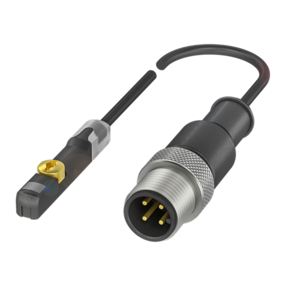
IO-Link BMF 415KW-HA W-5 Série
Balluff IO-Link BMF 415KW-HA W-5 Série Manuels
Manuels et Guides d'utilisation pour Balluff IO-Link BMF 415KW-HA W-5 Série. Nous avons
1
Balluff IO-Link BMF 415KW-HA W-5 Série manuel disponible en téléchargement PDF gratuit: Notice D'utilisation
Balluff IO-Link BMF 415KW-HA W-5 Série Notice D'utilisation (218 pages)
Marque:
Balluff
| Catégorie:
Capteurs
| Taille: 6.47 MB
Table des Matières
Table des Matières
5
Benutzerhinweise
7
Verwendete Symbole Und Konventionen
7
Lieferumfang
7
Zulassungen Und Kennzeichnungen
7
Verwendete Abkürzungen
7
Sicherheit
8
Bestimmungsgemäße Verwendung
8
Allgemeines Zur Sicherheit
8
Bedeutung Der Warnhinweise
8
Entsorgung
8
Aufbau Und Funktion
9
LED-Anzeige
10
Einbau Und Anschluss
11
Sensor Montieren
11
Kabel Fixieren
11
Elektrischer Anschluss
12
3-Polige Sensoren
12
4-Polige Sensoren Mit IO-Link
12
Anschlussschaltbilder Der Verschiedenen Ausprägungen
12
Inbetriebnahme
13
System In Betrieb Nehmen
13
Hinweise Zum Betrieb
13
IO-Link-Schnittstelle
14
Kommunikationsparameter
14
Prozessdaten (PD)
14
Identifikationsdaten
15
Systembefehle
15
Parameterdaten
16
FSS (Fixed Switching Signal)
16
Ausgangskonfiguration
16
Elektrische Merkmale
22
Notes To The User
31
Symbols And Conventions
31
Scope Of Delivery
31
Approvals And Markings
31
Abbreviations
31
Intended Use
32
General Safety Notes
32
Explanation Of The Warnings
32
Disposal
32
Construction And Function
33
Product Description
33
LED Display
34
Installation And Connection
35
Mounting The Sensor
35
Attach Cable
35
Electrical Connection
36
4-Pin Sensors With IO-Link
36
Wiring Diagrams For The Various Versions
36
Startup
37
11 5.2 Operating Notes
37
Starting Up The System
37
IO-Link Interface
38
12 6.2 Process Data (PD)
38
Communication Parameters
38
System Commands
39
Output Configuration
40
Diagnostic Suppression
41
Boot Cycle Counter
42
Data Storage
43
Diagnostic Parameters
44
Device Error Messages
45
Detection Range/Measuring Range
46
Ambient Conditions
46
Electrical Characteristics
46
Accessories
47
Part Label
49
Symboles et Conventions Utilisés
55
Fourniture
55
Homologations et Certifications
55
Abréviations Utilisées
55
Sécurité
56
Utilisation Conforme aux Prescriptions
56
Généralités Sur la Sécurité
56
Signification des Avertissements
56
Élimination
56
Structure et Fonction
57
Description du Produit
57
Structure et Fonction (Suite)
58
Affichage à LED
58
Montage et Raccordement
59
Montage du Capteur
59
Fixation du Câble
59
Raccordement Électrique
60
Capteurs 3 Pôles
60
Capteurs 4 Pôles Avec IO-Link
60
Schémas de Raccordement des Différentes Versions
60
Mise en Service du Système
61
Conseils D'utilisation
61
Données de Processus (DP)
62
Données D'identification
63
Ordres Système
63
Valeurs Seuils pour L'avertissement de Température
66
Compteur de Cycles de Démarrage
66
Catégorie Signification
68
Messages D'erreur de L'appareil
69
Caractéristiques Techniques
70
Accessoires
71
Écran de Protection Contre les Éclaboussures de Soudure
71
Clip de Câble Rainure en T
71
Annexe
73
Plaque Signalétique
73
Marquage du Câble
73
Simboli E Segni Utilizzati
79
Dotazione
79
Autorizzazioni E Contrassegni
79
Abbreviazioni Utilizzate
79
Uso Conforme
80
Informazioni DI Sicurezza
80
Significato Delle Avvertenze
80
Smaltimento
80
Struttura E Funzionamento
81
Descrizione Del Prodotto
81
Indicatore LED
82
Montaggio E Collegamento
83
Montare Il Sensore
83
Fissaggio Del Cavo
83
Collegamento Elettrico
84
Sensori A 3 Poli
84
Sensori A 4 Poli Con IO-Link
84
Schemi DI Collegamento Delle Diverse Versioni
84
Messa In Funzione
85
Messa In Funzione Del Sistema
85
Avvertenze Per Il Funzionamento
85
Interfaccia IO-Link
86
Parametri DI Comunicazione
86
Dati DI Processo (PD)
86
Dati Identificazione
87
Comandi DI Sistema
87
Dati Parametrici
88
FSS (Fixed Switching Signal)
88
Configurazione DI Uscita
88
Tempo DI Soppressione Del Disturbo
89
Indagine Diagnostica
89
Rilevamento Temperatura
89
Segnali DI Errore Apparecchi
93
Campo DI Rilevamento/Campo DI Misura
94
Condizioni Ambientali
94
Caratteristiche Elettriche
94
Legenda Codici DI Identificazione
96
Targhetta DI Identificazione
97
Símbolos Y Convenciones Utilizados
103
Volumen de Suministro
103
Homologaciones E Identificaciones
103
Abreviaturas Utilizadas
103
Uso Debido
104
Generalidades Sobre la Seguridad
104
Significado de Las Advertencias
104
Eliminación de Desechos
104
Estructura Y Funcionamiento
105
Descripción de Producto
105
Indicador LED
106
Montaje Y Conexión
107
Montar El Sensor
107
Fijar El Cable
107
Conexión Eléctrica
108
Sensores de 3 Polos
108
Sensores de 4 Polos Con IO-Link
108
Esquemas de Conexiones de Los Diferentes Valores
108
Puesta en Servicio
109
Puesta en Servicio Del Sistema
109
Indicaciones Sobre El Servicio
109
Interfaz IO-Link
110
Parámetros de Comunicación
110
Datos de Proceso (PD)
110
Datos de Identificación
111
Comandos Del Sistema
111
Datos de Parámetros
112
Supresión Del Diagnóstico
113
Captación de Temperatura
113
Valores Límite Para El Aviso de Temperatura
114
Contador de Horas de Servicio
114
Contador de Ciclos de Arranque
114
Bloqueos de Acceso (Device Access Locks)
115
Perfiles Y Funciones (Profilecharacteristic)
115
Estructura de Los Datos de Proceso (PD Input Descriptor)
116
Datos de Diagnóstico
116
Parámetros de Diagnóstico
116
Mensajes de Error de Aparato
117
Datos Técnicos
118
Zona de Captación/Zona Medible
118
Condiciones Ambientales
118
Indicadores
118
Características Eléctricas
118
Conexión Eléctrica
118
Salida/Interfaz
118
Datos Mecánicos
118
Escudo Protector Contra Proyecciones de Soldadura
118
Seguridad Funcional
118
Escudo Protector Contra Proyecciones de Soldadura
119
Clip de Cable Con Ranura en T
119
Código de Modelo
120
Anexo
121
Placa de Características
121
Impresión de Cable
121
Símbolos E Convenções Empregados
127
Abrangência Do Fornecimento
127
Utilização Conforme Programado
128
Informações Gerais de Segurança
128
Significado Dos Avisos de Advertência
128
Descrição Do Produto
129
Conexão Elétrica
132
Inicialização Do Sistema
133
Avisos Sobre O Funcionamento
133
Dados de Identificação
135
FSS (Fixed Switching Signal) 0X0039
136
Dados de Diagnóstico
140
Parâmetros de Diagnóstico
140
Lista de Eventos
140
Placa de Identificação
145
用户提示 适用性
151
所使用的符号和惯例
151
供货范围
151
认证和标志
151
使用的缩写
151
安全性 按规定使用
152
安全概述
152
警告提示的意义
152
废弃处理
152
结构与功能
153
Led显示
154
安装和连接 安装传感器
155
固定电缆
155
电子接口
156
带 IO-Link 的4极传感器
156
不同版本的接线图
156
调试运行 系统投入使用
157
运行说明
157
IO-Link接口
158
识别数据
159
系统命令
159
Device Configuration
160
参数数据
160
FSS (Fixed Switching Signal / 固定开关传感器)
160
干扰抑制时间
161
诊断抑制
161
温度探测
161
温度警告的阈值
162
运行小时计数器
162
引导周期计数器
162
数据保存(Data Storage)
163
设备访问锁 (Device Access Locks)
163
配置文件和功能 (Profilecharacteristic)
163
诊断参数
164
事件列表
164
设备故障信息
165
技术参数
166
探测范围/测量范围
166
环境条件
166
电气特征
166
电子接口
166
输出端/接口
166
机械数据
166
功能安全性
166
利用者情報 適用範囲
175
同梱品
175
認証と認証マーク
175
使用されている省略形
175
安全に関する一般事項
176
警告表示の説明
176
取り付けと接続 センサの取り付け
179
ケーブルを固定する
179
各種仕様の接続図
180
セットアップ システムのセットアップ
181
プロセスデータ(Pd
182
識別データ
183
システムコマンド
183
0X00B4
184
0X0420 (1056) 0
184
Condition Monitoring
184
0X0052
184
Device Temperature (Véase El Capítulo 6.5.5)
184
0X0053
184
0X0057
184
Diagnosis Suppression Configuration
184
Disturbance Suppression Duration
184
Temperature Thresholds
184
外乱抑制時間
185
診断の差し止め
185
温度検知
185
0X0058
186
Operating Hours (Véase El Capítulo 6.5.7)
186
Boot Cycle Counter (Véase El Capítulo 6.5.8)
186
温度警告用しきい値
186
作動時間カウンタ
186
ブートサイクルカウンター
186
0X0003
187
Data Storage (Véase El Capítulo 6.5.9)
187
0X000C
187
0X000D
187
0X000E
188
PD Input Descriptor (Véase El Capítulo 6.5.12)
188
Process Data
188
6.5.12 プロセスデータの構造
188
診断データ
188
診断パラメータ
188
Руководство По Эксплуатации
195
Указания Для Пользователя
199
Сфера Действия
199
Используемые Символы И Условные Обозначения
199
Объем Поставки
199
Разрешения И Маркировки
199
Используемые Сокращения
199
Безопасность
200
Общие Указания По Технике Безопасности
200
Значение Предупреждающих Указаний
200
Конструкция И Принцип Действия
201
Описание Продукции
201
Светодиодная Индикация
202
Монтаж И Подключение
203
Установка Датчика
203
Фиксация Кабеля
203
3-Полюсные Датчики
204
Схемы Электрических Соединений Для Разных Исполнений
204
Ввод В Эксплуатацию
205
Ввод В Эксплуатацию Системы
205
Указания По Эксплуатации
205
Out
206
Интерфейс IO-Link
206
Параметры Передачи Данных
206
Данные Процесса (PD)
206
Идентификационные Данные
207
Системные Команды
207
Заводская Табличка
217
Publicité
Publicité
Produits Connexes
Balluff BML-M02-I 45-A3-M0100-R0000
Balluff BML-M02-I 46-A0-M0200-R0010
Balluff BML-M02-I 46-A0-M0200-R0000
Balluff BML-M02-I 4 5-A3-M0100-R0030
Balluff BML-M02-I 4 5-A3-M0100-R0060
Balluff BTL PF 400-C12NL-0-000S04 Serie
Balluff 574-41014
Balluff 574-41015
Balluff 574-41018
Balluff 574-41019
Balluff Catégories
Capteurs
Équipement industriel
Transducteurs
Appareils de mesure
Instruments de mesure
Plus Manuels Balluff
Connexion
Se connecter
OU
Se connecter avec Facebook
Se connecter avec Google
Télécharger le manuel
Télécharger depuis le disque dur
Télécharger depuis l'URL