Daikin 2MXM68A2V1B9 Manuel D'installation
Masquer les pouces
Voir aussi pour 2MXM68A2V1B9:
- Manuel d'installation (32 pages) ,
- Manuel d'installation (32 pages) ,
- Guide de référence installateur (92 pages)

Manuels Connexes pour Daikin 2MXM68A2V1B9


Sommaire des Matières pour Daikin 2MXM68A2V1B9
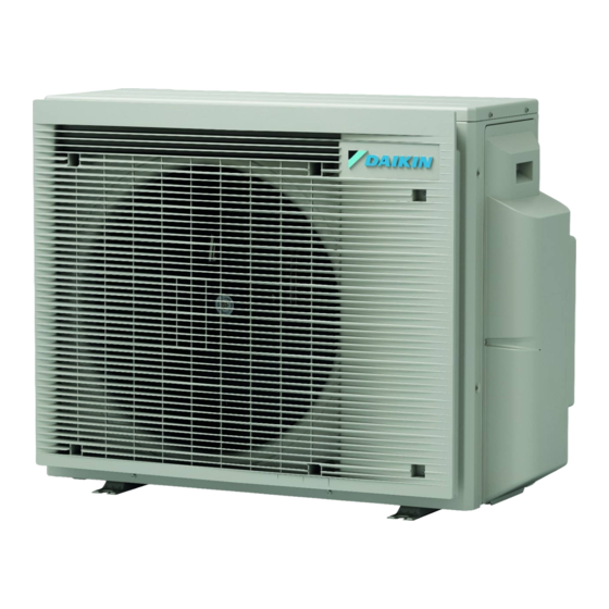
- Page 1 Installation manual R32 Split series 2MXM68A2V1B9 3MXM40A2V1B9 3MXM52A2V1B9 3MXM68A2V1B9 4MXM68A2V1B9 Installation manual 4MXM80A2V1B9 English R32 Split series 5MXM90A2V1B9...
- Page 2 4P710996-1...
- Page 3 4P710996-1...
- Page 4 4P710996-2...
- Page 5 4P710996-2...
- Page 6 ▪ Preparation of the installation, reference data, … 9.3.1 To turn ON the night quiet mode......... 17 About heat mode lock..............17 ▪ Format: Digital files on https://www.daikin.eu. Use the search 9.4.1 To turn ON heat mode lock......... 17 function to find your model.
- Page 7 ▪ Incomplete flaring may cause refrigerant gas leakage. Daikin website (publicly accessible). ▪ Do NOT re-use flares. Use new flares to prevent ▪ The full set of the latest technical data is available on the Daikin refrigerant gas leakage. Business Portal (authentication required).
- Page 8 3 About the box WARNING DANGER: RISK OF BURNING/SCALDING ALWAYS use multicore cable for power supply cables. WARNING WARNING ▪ Before carrying out any maintenance or repair activity, Use an all-pole disconnection type breaker with at least ALWAYS switch off the circuit breaker on the supply 3 ...
- Page 9 4 Unit installation Prevailing wind direction Unit installation Air outlet Do NOT install the unit in sound sensitive areas (e.g. near a WARNING bedroom), so that the operation noise will cause no trouble. Installation shall be done by an installer, the choice of Note: If the sound is measured under actual installation conditions, materials and installation shall comply with the applicable the measured value might be higher than the sound pressure level...
- Page 10 5 Piping installation Drain hole To close the drain holes and attach the drain socket 1 Install drain caps (accessory f) and (accessory g). Make sure the edges of the drain caps close off the holes completely. 2 Install the drain socket. Drain hole.
- Page 11 5 Piping installation Shortest allowable length per room is 3 m. 5MXM90 Gas piping 2× Ø9.5 mm (3/8") Outdoor unit Refrigerant piping Refrigerant piping length to each indoor total length 1× Ø12.7 mm (1/2") unit 2× Ø15.9 mm (5/8") 2MXM68, ≤25 m ≤50 m 3MXM40, INFORMATION 3MXM52, Usage of reducers might be required based on the indoor 3MXM68...
- Page 12 5 Piping installation Outdoor unit Total indoor unit capacity Reducer type Connection class Ø15.9 mm → Ø9.5 mm 3MXM68, 4MXM68 ≤11.0 kW Ø15.9 mm → Ø9.5 mm 4MXM80 ≤14.5 kW Connection examples: 5MXM90 ≤15.6 kW ▪ Connecting a Ø12.7 mm pipe to a Ø15.9 mm gas pipe connection port INFORMATION It is NOT possible to connect only 1 indoor unit.
- Page 13 6 Charging refrigerant 5.3.2 To perform vacuum drying WARNING Connect the refrigerant piping securely before running the DANGER: RISK OF EXPLOSION compressor. If the refrigerant piping is NOT connected and the stop valve is open when the compressor is run, air will Do NOT open the stop valves before the vacuum drying is be sucked in.
- Page 14 6 Charging refrigerant WARNING To charge additional refrigerant The appliance shall be stored so as to prevent mechanical WARNING damage and in a well-ventilated room without continuously operating ignition sources (e.g. open flames, an operating ▪ Only use R32 as refrigerant. Other substances may gas appliance, or an operating electric heater).
- Page 15 7 Electrical installation leaks" [ 4 13]. 2 Perform the leak tests see "5.3.1 To check for Power supply 3 Charge refrigerant. Phase Current 3MXM40:16.0 A 4 Check for refrigerant leaks after charging (see above). 2MXM68:19.8 A 3MXM52:16.3 A Electrical installation 3MXM68:19.8 A 4MXM68:19.8 A DANGER: RISK OF ELECTROCUTION 4MXM80:20.4 A WARNING 5MXM90:25.9 A...
- Page 16 8 Finishing the outdoor unit installation Finishing the outdoor unit installation To finish the outdoor unit installation DANGER: RISK OF ELECTROCUTION ▪ Make sure that the system is earthed properly. ▪ Turn OFF the power supply before servicing. ▪ Install the switch box cover before turning ON the Terminal for room (A, B, C, D, E)* power supply.
- Page 17 9 Configuration 9.3.1 To turn ON the night quiet mode 1 Remove the switch cover on the service PCB. 1× 3 Turn ON the main power supply. About priority room function INFORMATION ▪ The priority room function requires initial settings to be made during the installation of the unit.
- Page 18 General commissioning checklist. Next commissioning instructions in this chapter, a general commissioning checklist is also available on the Daikin 10.3 Trial operation and testing Business Portal (authentication required). For the Hybrid for Multi, certain precautions are required before The general commissioning checklist is complementary to using this function.
- Page 19 ▪ Follow the product diagnosis procedures. For details of Daikin Business Portal (authentication required). product error diagnosis refer to service manual. general maintenance/inspection...
- Page 20 ▪ A subset of the latest technical data is available on the regional refer to PCB inside your unit) Daikin website (publicly accessible). Connector (frame ground) ▪ The full set of the latest technical data is available on the Daikin Harness Business Portal (authentication required). H*P, LED*, V*L...
- Page 21 13 Technical data Symbol Meaning Symbol Meaning Swing motor S*RH Humidity sensor MR*, MRCW*, MRM*, MRN* Magnetic relay S*W, SW* Operation switch Neutral SA*, F1S Surge arrester n=*, N=* Number of passes through ferrite SR*, WLU Signal receiver core Selector switch Pulse-amplitude modulation SHEET METAL Terminal strip fixed plate...
- Page 22 13 Technical data Muffler with filter Thermistor (liquid) Refrigerant flow: heating Solenoid valve Filter 3MXM40, 3MXM52 7.9CuT 7.9CuT 6.4CuT 7.9CuT (6.4CuT) 7.9CuT 12.7CuT 7.9CuT 6.4CuT 7.9CuT 9.5CuT 7.9CuT (6.4CuT) 9.5CuT 7.9CuT 6.4CuT 9.5CuT (6.4CuT) 12.7CuT 9.5CuT 12.7CuT 15.9CuT 12.7CuT (9.5CuT) 9.5CuT 12.7CuT (12.7CuT)
- Page 23 13 Technical data 4MXM68 7.9CuT 7.9CuT 6.4CuT (6.4CuT) 7.9CuT 7.9CuT 12.7CuT 7.9CuT 7.9CuT 6.4CuT 9.5CuT (6.4CuT) 7.9CuT 9.5CuT 7.9CuT 6.4CuT (6.4CuT) 7.9CuT 6.4CuT 6.4CuT 9.5CuT (6.4CuT) 9.5CuT 9.5CuT 12.7CuT 12.7CuT 15.9CuT 12.7CuT 15.9CuT 9.5CuT 12.7CuT (9.5CuT) 9.5CuT 12.7CuT (9.5CuT) 12.7CuT (12.7CuT) 15.9CuT 12.7CuT...
- Page 24 13 Technical data 5MXM90 7.9CuT 7.9CuT 7.9CuT 6.4CuT 9.5CuT (6.4CuT) 7.9CuT 9.5CuT 7.9CuT 6.4CuT 7.9CuT (6.4CuT) 7.9CuT 12.7CuT 7.9CuT 7.9CuT 7.9CuT 6.4CuT 9.5CuT 7.9CuT (6.4CuT) 9.5CuT 7.9CuT 7.9CuT 7.9CuT 6.4CuT 6.4CuT 9.5CuT (6.4CuT) 9.5CuT 7.9CuT 6.4CuT (6.4CuT) 9.5CuT 12.7CuT 12.7CuT 15.9CuT 12.7CuT 15.9CuT...
- Page 28 3P774208-3 2024.05...