Publicité
Les langues disponibles
Les langues disponibles
Liens rapides
D G F
6000-4080-0000-1XXD7 40800-2024-D7 V101 25/01/2024
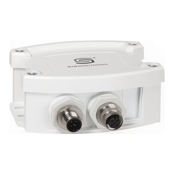
Temperature sensor Type ATM2-T3-MB
D
Bedienungs- und Montageanleitung
Außen- ⁄ Feuchtraum-Temperaturmessumformer,
kalibrierfähig, mit Modbus-Anschluss
G
Operating and Mounting Instructions
Outside temperature ⁄ wet room
temperature measuring transducer,
calibratable, with Modbus connection
F
Notice d'instruction
Sonde de température extérieure ⁄
de locaux humides avec convertisseur,
étalonnable, avec raccordement Modbus
S+S REGELTECHNIK GMBH
THURN-UND-TAXIS - STR. 22
90411 NÜRNBERG ⁄ GERMANY
FON +49 ( 0 ) 911 ⁄ 5 19 47- 0
mail@SplusS.de
www.SplusS.de
134r0067/002;1: Frozen :29-Jan-2024
CARTONS
ET EMBALLAGE
PAPIER À TRIER
Publicité

Manuels Connexes pour S+S Regeltechnik ATM2-T3-MB


Sommaire des Matières pour S+S Regeltechnik ATM2-T3-MB
- Page 1 D G F 6000-4080-0000-1XXD7 40800-2024-D7 V101 25/01/2024 Temperature sensor Type ATM2-T3-MB Bedienungs- und Montageanleitung Außen- ⁄ Feuchtraum-Temperaturmessumformer, kalibrierfähig, mit Modbus-Anschluss Operating and Mounting Instructions Outside temperature ⁄ wet room temperature measuring transducer, calibratable, with Modbus connection Notice d’instruction Sonde de température extérieure ⁄...
- Page 2 D G F Temperature sensor Type ATM2-T3-MB Maßzeichnung Type ATM2-T3-MB Dimensional drawing Plan coté [mm] 78.5 M20x1.5 134r0067/002;1: Frozen :29-Jan-2024...
- Page 3 Type ATM2-T3-MB Rev. Data - V40 Kalibrierfähiger Außentemperaturmessumformer Type ATM 2 - T3 - MB, mit Modbus-Anschluss, im schlagfesten Kunststoff gehäuse mit Schnell- verschluss schrauben, misst Temperatur (–50...+150 °C). Internationales Einheiten system SI (default) ist auf Imperial umstellbar (über Modbus). Der Aufputzfühler dient zur Erfassung der Temperatur in gasförmigen Medien.
- Page 4 Type ATM2-T3-MB Rev. Data - V40 Schaltbild Stecker Display DIP A offset 1 2 3 4 5 6 7 8 1 2 3 4 5 6 7 8 address DIP B 1 2 3 4 5 6 mode DIP A: Busadresse...
- Page 5 Type ATM2-T3-MB | Konfiguration BUSADRESSE MODBUS Busadresse (binärcodiert, Wertigkeit 1 bis 247 einstellbar) DIP-Schalter [ A ] DIP 1 DIP 2 DIP 3 DIP 4 DIP 5 DIP 6 DIP 7 DIP 8 DIP A 1 2 3 4 5 6 7 8 Beispiel zeigt 128 + 64 + 1 = 193 als Modbus-Adresse.
- Page 6 Type ATM2-T3-MB | Telegramme TELEGRAMME Function 04 Read Input Register Register Parameter Data Type Value Range 3x0001 Temperatur Ohne Filterung Signed 16 Bit – 500...+ 1500 – 50.0 ... +150.0 °C – 580...+ 3020 – 58.0 ... +302.0 °F – 999...+ 9999 Überlauf...
- Page 7 Type ATM2-T3-MB | Telegramme Function 08 Diagnostics Folgende Sub Function Codes werden unterstützt Sub Function Parameter Data Type Antwort Code Echo der Sendedaten Echodaten (Loopback) Neustart Modbus Echo Telegramm (Reset Listen Only Mode) Aktivierung Listen Only Mode Keine Antwort Lösche Zähler Echo Telegramm Zähler Bustelegramme...
- Page 8 Modbus | Installation Allgemeiner Aufbau Busstruktur MODBUS RTU-Master Passiver Aktiver Abzweig Abzweig RS-485 Stammleitung Leitungs- Leitungs- (Trunk-Kabel) abschluss abschluss Stichleitung (Drop-Kabel) Slave n Stichleitung: Mehrfachabzweigung n: Slave 1 Slave 2 kürzer 20m kürzer 40m/n Bustopologie mit Abschluss- und Vorspannungswiderständen MODBUS RTU-Master Pull-Up- / Vorspannungswiderstand...
- Page 9 Montage und Inbetriebnahme Die Geräte sind im spannungslosen Zustand anzuschließen. Der Anschluss Hinweise zum mechanischen Ein- und Anbau: Der Einbau hat unter Berücksichtigung der einschlägigen, für den Messort der Geräte darf nur an Sicherheitskleinspannung er folgen. Folgeschäden, gültigen Vorschriften und Standards (wie z. B. Schweißvorschriften usw.) welche durch Fehler an diesem Gerät entstehen, sind von der Gewähr- zu erfolgen.
- Page 10 Wichtige Hinweise Als AGB gelten ausschließlich unsere sowie die gültigen „Allgemeinen Lieferbedingungen für Erzeugnisse und Leistungen der Elektro industrie“ (ZVEI Bedingungen) zuzüglich der Ergänzungsklausel „Erweiterter Eigentumsvorbehalt“. Außerdem sind folgende Punkte zu beachten: – Vor der Installation und Inbetriebnahme ist diese Anleitung zu lesen und die alle darin gemachten Hinweise sind zu beachten! –...
- Page 11 134r0067/002;1: Frozen :29-Jan-2024...
- Page 12 Type ATM2-T3-MB Rev. Data - V40 Calibratable outside temperature measurement transducer Type ATM 2 - T3 - MB, with Modbus connection, in an impact-resistant plastic housing with quick-locking screws, measures temperature (–50...+150 °C). International system of units SI (default) can be changed to imperial (via Modbus).
- Page 13 Type ATM2-T3-MB Rev. Data - V40 Schematic diagram Plug for display DIP A offset 1 2 3 4 5 6 7 8 1 2 3 4 5 6 7 8 address DIP B 1 2 3 4 5 6 mode...
- Page 14 Type ATM2-T3-MB | Configuration BUS ADDRESS MODBUS Bus address (binary coded, value selectable from 1 to 247) DIP switch [ A ] DIP 1 DIP 2 DIP 3 DIP 4 DIP 5 DIP 6 DIP 7 DIP 8 DIP A 1 2 3 4 5 6 7 8 Example shows 128 + 64 + 1 = 193 as Modbus address.
- Page 15 Type ATM2-T3-MB | Telegrams TELEGRAMS Function 04 Read Input Register Register Parameter Data Type Value Range 3x0001 Temperature Without filtering Signed 16 Bit – 500...+ 1500 – 50.0 ... +150.0 °C – 580...+ 3020 – 58.0 ... +302.0 °F – 999...+ 9999...
- Page 16 Type ATM2-T3-MB | Telegrams Function 08 Diagnostics The following sub function codes are supported Sub Function Parameter Data Type Answer Code Echo of transmission data Echo data (Loopback) Restart Modbus Echo telegram (Reset listen-only mode) Activation listen-only mode No answer...
- Page 17 Modbus | Installation General layout of bus structure MODBUS RTU-Master Passive Active branch branch RS-485 Trunk line Line Line termination termination Stub line Slave n Stub line: Multiple branch n: Slave 1 Slave 2 shorter 20m shorter 40m/n Bus topology with terminating and bias resistors MODBUS RTU-Master Pull-up /...
- Page 18 Installation and Commissioning Devices are to be connected under dead-voltage condition. Devices Notes regarding mechanical mounting and attachment: Mounting shall take place while observing all relevant regulations and must only be connected to safety extra-low voltage. Consequential standards applicable for the place of measurement (e.g. such as welding damages caused by a fault in this device are excluded from warranty or instructions, etc.).
- Page 19 Important notes Our “General Terms and Conditions for Business“ together with the “General Conditions for the Supply of Products and Services of the Electrical and Elec- tronics Industry“ (ZVEI conditions) including supplementary clause “Extended Retention of Title“ apply as the exclusive terms and conditions. In additionIn addition, the following points are to be observed: –...
- Page 20 134r0067/002;1: Frozen :29-Jan-2024...
- Page 21 Type ATM2-T3-MB Rev. Data - V40 Convertisseur de température extérieure étalonnable Type ATM 2 - T3 - MB, avec raccordement Modbus, boîtier en plastique résistant aux chocs avec vis de fermeture rapide, au choix avec / sans écran, mesure la température (–50...+150 °C). Le système international d’unités SI (par défaut) peut être commuté...
- Page 22 Type ATM2-T3-MB Rev. Data - V40 Schéma de raccordement Plug for display DIP A offset 1 2 3 4 5 6 7 8 1 2 3 4 5 6 7 8 address DIP B 1 2 3 4 5 6...
- Page 23 Type ATM2-T3-MB | Configuration ADRESSE DU BUS MODBUS Adresse du bus (code binaire, valance réglable de 1 à 247) Interrupteur DIP [ A ] DIP 1 DIP 2 DIP 3 DIP 4 DIP 5 DIP 6 DIP 7 DIP 8...
- Page 24 Type ATM2-T3-MB | Télégrammes TÉLÉGRAMMES Function 04 Read Input Register Registre Paramètres Data Type Value Range 3x0001 Température Sans filtrage Signed 16 Bit – 500...+ 1500 – 50.0 ... +150.0 °C – 580...+ 3020 – 58.0 ... +302.0 °F – 999...+ 9999 Dépassement...
- Page 25 Type ATM2-T3-MB | Télégrammes Function 08 Diagnostics Les codes sous-fonction suivants sont pris en charge Code sous- Paramètres Data Type Réponse fonction Écho des données d’émission Données d’écho (loopback-rebouclage) Redémarrage Modbus (Reset Listen Télégramme d’écho Only Mode – Réinit Mode Écoute Seule) Activation Listen Only Mode Pas de réponse...
- Page 26 Modbus | Installation Structure générale du bus MODBUS RTU-Master Raccord Raccord actif passif RS-485 Ligne principale Fin de ligne Fin de ligne (câble principal) Tronçon (câble de dérivation) Slave n Tronçon : Poly-raccord n : Slave 1 Slave 2 moins de 20 m moins de 40 m / n Topologie du bus avec résistances de charge et polarisation MODBUS...
- Page 27 Montage et mise en service Les raccordements électriques doivent être exécutés HORS TENSION. Consignes pour l’installation mécanique : Effectuer le montage en tenant compte des dispositions et règles Veillez à ne brancher l’appareil que sur un réseau de très basse tension standards à...
- Page 28 Généralités Seules les CGV de la société S+S, les « Conditions générales de livraison du ZVEI pour produits et prestations de l’industrie électronique » ainsi que la clause complémentaire « Réserve de propriété étendue » s’appliquent à toutes les relations commerciales entre la société S+S et ses clients. Il convient en outre de respecter les points suivants : –...
- Page 29 134r0067/002;1: Frozen :29-Jan-2024...
- Page 30 134r0067/002;1: Frozen :29-Jan-2024...
- Page 31 Reprint in full or in parts requires permission from S+S Regeltechnik GmbH. La reproduction des textes même partielle est uniquement autorisée après accord de la société S+S Regeltechnik GmbH. Irrtümer und technische Änderungen vorbehalten. Alle Angaben entsprechen unserem Kenntnisstand bei Veröffentlichung. Sie dienen nur zur Information über unsere Produkte und deren Anwendungsmöglichkeiten, bieten jedoch keine Gewähr für bestimmte Produkteigenschaften.
- Page 32 D G F Busadresse, binärcodiert Bus address, binary coded Adresse du bus, code binaire 0 0 0 0 0 0 0 1 0 0 1 1 0 0 1 1 0 1 1 0 0 1 0 1 1 0 0 1 0 1 1 1 1 1 0 0 1 0 0 1 0 0 0 0 0 0 1 0 0 0 1 1 0 1 0 0...