Festo CPX-CTEL4-M12-5POL Manuel D'instructions
Masquer les pouces
Voir aussi pour CPX-CTEL4-M12-5POL:
- Manuel d'installation et mise en service (120 pages) ,
- Traduction de la notice originale (63 pages) ,
- Mode d'emploi (59 pages)
Table des Matières
Publicité
Les langues disponibles
Les langues disponibles
Liens rapides
Publicité
Table des Matières

Manuels Connexes pour Festo CPX-CTEL4-M12-5POL


Sommaire des Matières pour Festo CPX-CTEL4-M12-5POL
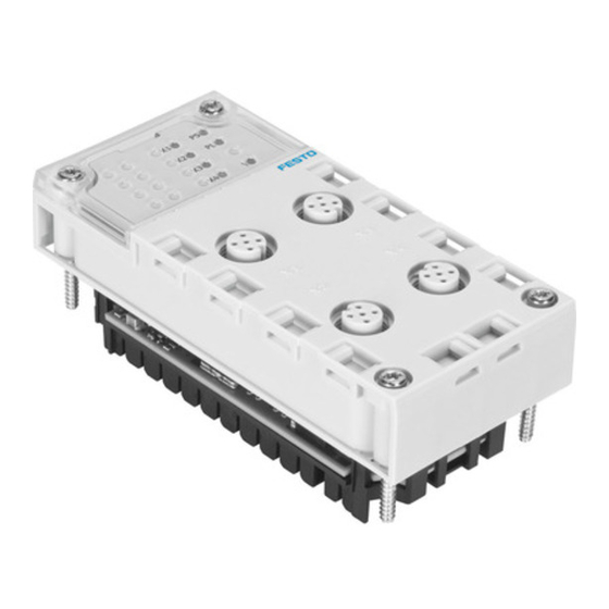
- Page 1 CPX-Terminal Kurz- beschreibung Brief description CPX-Funktions- modul Typ CPX-CTEL- 4-M12-5POL CPX function module Type CPX-CTEL- 4-M12-5POL – Deutsch – English – Español – Français – Italiano – 中文 758324 1205NH...
- Page 2 ..........Edition: 1205NH Original: de © (Festo AG & Co. KG, D-73726 Esslingen, Germany, 2012) Internet: http://www.festo.com E-Mail: service_international@festo.com...
- Page 3 Anschluss des CPX-Terminals an. • Der CTEL-Master enthält elektrostatisch gefährdete Bauelemente. Berühren Sie deshalb keine Bau- elemente. Beachten Sie die Handhabungsvorschrif- ten für elektrostatisch gefährdete Bauelemente. Hinweis Nehmen Sie nur ein komplett montiertes und verdrahtetes CPX-Terminal in Betrieb. Festo CPX-CTEL-Z6 1205NH Deutsch...
-
Page 4: Anschluss- Und Anzeigeelemente
Status-LEDs für I-Port 1 … 4 und CPX-spezifische LEDs I-Port-Schnittstellen 1 … 4 Typenschild Status-LEDs für I-Port CPX-/steuerungsspez. LEDs Status I-Port 1 … 4 Power System (grün) … (grün/rot) Verbindungs-Status OK, Power Load (grün) Device-Fehler, Konfigurationsfehler oder CPX-Peripheriefehler (rot) Kompatibilitätsfehler Festo CPX-CTEL-Z6 1205NH Deutsch... - Page 5 Blinkt grün: Unterspannung Aus: PL nicht vorhanden oder ungenutzt Aus: CPX-Kommunikation in Ordnung Rot: CPX startet oder CPX-Fehler X1…X4 Leuchtet grün: Device OK Blinkt grün: Diagnose Leuchtet rot: I-Port Fehler Blinkt rot: Konfigurationsfehler Aus: Kein Device erkannt Festo CPX-CTEL-Z6 1205NH Deutsch...
- Page 6 Schalten Sie die Spannungsversorgung aus, bevor Sie das CTEL-Master-Modul demontieren oder montieren (Gefahr von Funktionsstörungen oder Beschädigung). Schrauben, Anzugsdrehmoment 0,9 … 1,1 Nm CTEL-Master-Modul Verkettungsblock, hier: beispielhaft mit Zusatzeinspeisung Demontage: • Schrauben herausdrehen und Steuerblock vorsichtig abheben. Festo CPX-CTEL-Z6 1205NH Deutsch...
- Page 7 Montage: 1. Dichtung und Dichtflächen prüfen und Anschlussblock wieder aufsetzen. 2. Schrauben von Hand über Kreuz anziehen. Anzugs- drehmoment 0,9 ... 1,1 Nm. 3.2 Einstellung der DIL-Schalter DIL-Schalter 1 DIL-Schalter 2 Festo CPX-CTEL-Z6 1205NH Deutsch...
- Page 8 16 Byte E/A (4 Byte je I-Port) DIL 2.2: ON DIL 2.1: ON 24 Byte E/A (6 Byte je I-Port) DIL 2.2: OFF DIL 2.1: ON 32 Byte E/A (8 Byte je I-Port) DIL 2.2: ON Festo CPX-CTEL-Z6 1205NH Deutsch...
- Page 9 Sie vermeiden damit Fehler beim Datenaustausch zwi- schen dem CTEL-Master-Modul und den angeschlos- senen Devices. Zur Sicherstellung der Schutzart IP65/IP67 müssen die nicht verwendeten I-Port-Schnittstellen mit Abdeck- kappen verschlossen werden. Diese müssen separat bestellt werden (Typ ISK-M12). Festo CPX-CTEL-Z6 1205NH Deutsch...
- Page 10 B. Typ CPX-GE-EV-S digitale Ausgänge (hier nicht verwendet) Verkettungsblock ohne Einspeisung, z. B. Typ CPX-GE-EV Betriebsspannung für Elektronik und Sensoren Verkettungsblock mit Zusatzein- speisung, z. B. Typ CPX-GE-EV-V Erdungsanschluss (Funktionserde, FE) Lastspannung für Ventile Festo CPX-CTEL-Z6 1205NH Deutsch...
- Page 11 , 0 V Lastspannung Ventile Erdungsanschluss (Funktionserde) n.c.: frei (not connected) A, B, C, D: Hinweis: Kupplung (Anschlussdose NECU-G78G4-C2) ist mit „1, 2, 3, 4“ gekennzeichnet. Zuordnung: D=1, C=2, B=3, A=4. Andere Kupplungen können davon abweichen. Festo CPX-CTEL-Z6 1205NH Deutsch...
- Page 12 1234 1234 Potentialausgleich Anschluss der Systemeinspeisung Externe Sicherungen Typ CPX-GE-EV-S (M18) Lastspannungsversorgung der Anschluss der Ventile bzw. Ausgänge ist getrennt Zusatzeinspeisung für abschaltbar elektrische Ventile Typ CPX-GE-EV-V (M18) Erdungsanschluss Pin 4 (M18-Stecker), ausgelegt für 16 A Festo CPX-CTEL-Z6 1205NH Deutsch...
-
Page 13: Technische Daten
(nach DIN/IEC 68/EN 60 068) Schwingung (Teil 2 – 6) Wand: SG 2, Hutschiene: SG 1 Schock (Teil 2 – 27) Wand: SG 2, Hutschiene: SG 1 Dauerschockfestigkeit (Teil 2 – 29) Wand und Hutschiene: SG 1 Festo CPX-CTEL-Z6 1205NH Deutsch... - Page 14 Elektronik/Sensoren (V EL/SEN – PL, aus Lastspannungsversorgung Ventile 1,6 A Potentialtrennung – zwischen Betriebsspannungsversorgung ja, bei potentialge- Elektronik/Sensoren PS (V ) und trennter Einspei- EL/SEN Lastspannungsversorgung Ventile PL (V sung – Versorgungen PS/PL zwischen den I-Ports nein Festo CPX-CTEL-Z6 1205NH Deutsch...
- Page 15 (elektronisch) separat für jeden I-Port – Verhalten nach Kurzschluss abhängig von Parameter „Verhalten nach I-Port-Kurz- schluss“ Parametrierung – Modul-Parameter – Diagnoseverhalten – Werkzeugwechselmodus – Failsafe pro Kanal – Forcing pro Kanal – Idle Mode pro Kanal Festo CPX-CTEL-Z6 1205NH Deutsch...
- Page 16 System- und Lastver- sorgung, nicht getrennt je I-Port Diagnose Modulorienterte Diagnose Unterspannung PS Unterspannung/Kurzschluss Module Unterspannung PL (über De- Kommunikationsfehler vice) Kommunikationsfehler Kurzschluss PS/PL Device-Fehler Sofern vom jeweiligen CPX-Feldbus-Master unterstützt. Beispiel: CPX-FB38 (EtherCAT), Rev.6 unterstützt keinen Idle Mode. Festo CPX-CTEL-Z6 1205NH Deutsch...
- Page 17 S The CTEL master includes electrostatically sensitive devices. Therefore, do not touch any components. Observe the handling specifications for electrostatic- ally sensitive devices. Note Only commission a CPX terminal which has been mounted and wired completely. Festo CPX-CTEL-Z6 1205NH English...
-
Page 18: Connection And Display Components
Name plate Status LEDs for I-Port CPX-/control-specific LEDs Status I-Port 1 … 4 Power system (green) … (green/red) Connection status OK, Power load (green) device error, configuration error or com- CPX peripheral error (red) patibility error Festo CPX-CTEL-Z6 1205NH English... - Page 19 Off: PL not on hand or unused Off: CPX communication OK Red: CPX starting or CPX error X1…X4 Illuminates green: Device OK Flashes green: Diagnostics Illuminated red: I-Port error Flashes red: Configuration error Off: No device detected Festo CPX-CTEL-Z6 1205NH English...
-
Page 20: Installation Instructions
CTEL master module (danger of operative malfunctions or damage). Screws, tightening torque 0.9 … 1.1 Nm CTEL master module Interlinking block, here, for example, with additional power supply Dismantling: Remove the screws and carefully lift up the control block. Festo CPX-CTEL-Z6 1205NH English... - Page 21 1. Check the seal and sealing surfaces and refit the con- nection block. 2. Tighten the screws by hand in diagonally opposite se- quence. Tightening torque 0.9 ... 1.1 Nm. 3.2 Setting the DIL switches DIL switch 1 DIL switch 2 Festo CPX-CTEL-Z6 1205NH English...
- Page 22 16 bytes I/O DIL 2.2: ON (4 bytes each I-Port) DIL 2.1: ON 24 bytes I/O DIL 2.2: OFF (6 bytes each I-Port) DIL 2.1: ON 32 bytes I/O DIL 2.2: ON (8 bytes each I-Port) Festo CPX-CTEL-Z6 1205NH English...
- Page 23 You will then avoid errors in data exchange between the CTEL master module and the connected devices. To ensure protection class IP65/IP67, the unused I-Port interfaces must be sealed with cover caps. These must be ordered separately (type ISK-M12). Festo CPX-CTEL-Z6 1205NH English...
- Page 24 (not used here) Interlinking block without supply, Operating voltage for e.g. type CPX-GE-EV electronics and sensors Interlinking block with additional Earth terminal (functional power supply, e.g. type earth, FE) CPX-GE-EV-V Load voltage for the valves Festo CPX-CTEL-Z6 1205NH English...
- Page 25 Load voltage valves earth terminal (functional earth) n.c.: free (not connected) A, B, C, D: Note: coupling(plug socket NECU-G78G4-C2) is marked with “1, 2, 3, 4”. Allocation: D=1, C=2, B=3, A=4. Other coup- lings can deviate from this. Festo CPX-CTEL-Z6 1205NH English...
- Page 26 CPX-GE-EV-S (M18) Load voltage supply of the valves Connection of the or outputs can be disconnected additional power separately supply for electric valves of type Earth terminal pin 4 (M18 plug), CPX-GE-EV-V (M18) designed for 16 A Festo CPX-CTEL-Z6 1205NH English...
-
Page 27: Technical Data
(as per DIN/IEC 68/EN 60 068) Wall: SG 2, H-rail: SG 1 Vibration (part 2 - 6) Wall: SG 2, H-rail: SG 1 Shock (part 2 - 27) Wall and H-rail: SG 1 Continuous shock resistance (part 2 – 29) Festo CPX-CTEL-Z6 1205NH English... - Page 28 Electrical isolation – between the operating voltage supply for the Yes, with potential- electronics/sensors PS (V ) and the load isolated supply EL/SEN voltage supply for the valves PL (V – Supply PS/PL between the I-Ports Festo CPX-CTEL-Z6 1205NH English...
- Page 29 – Behaviour after short circuit Depending on parameter “Be- haviour after short circuit” Parameterisation – Module parameters – Diagnostic behaviour – Tool change mode – Failsafe per channel – Forcing per channel – Idle mode per channel Festo CPX-CTEL-Z6 1205NH English...
- Page 30 Module-oriented diagnostics Undervoltage PS Undervoltage/short-circuit modules Undervoltage PL (over device) Communication errors Communication errors Short-circuit PS/PL Device error If supported by the respective CPX fieldbus master. Example: CPX-FB38 (EtherCAT), Rev.6 does not support an idle mode. Festo CPX-CTEL-Z6 1205NH English...
- Page 31 Por este motivo no se debe tocar ninguno de los componentes. Observe las especificaciones sobre manipulación de componen- tes sensibles a las descargas electrostáticas. Nota Ponga en funcionamiento un terminal CPX solo cuando se halle completamente montado y cableado. Festo CPX-CTEL-Z6 1205NH Español...
-
Page 32: Elementos De Conexión E Indicación
Específicos del control de CPX LEDs Estado I-Port 1 … 4 Power System (verde) … (verde/rojo) Power Load (verde) Estado de conexión OK, fallo del aparato, Error de periferia del CPX error de configuración o (rojo) error de compatibilidad Festo CPX-CTEL-Z6 1205NH Español... - Page 33 Rojo: arranque de CPX o error de CPX X1…X4 Encendido en verde: aparato OK Intermitente en verde: diagnosis Encendido en rojo: error de I-Port Intermitente en rojo: error de configuración Apagado: no se detecta ningún aparato Festo CPX-CTEL-Z6 1205NH Español...
- Page 34 Tornillos, par de apriete 0,9 … 1,1 Nm Módulo master CTEL-Master Bloque de distribución, aquí: con fuente de alimentación adicional como ejemplo Desmontaje: Desenroscar los tornillos y levantar con cuidado el bloque de control. Festo CPX-CTEL-Z6 1205NH Español...
- Page 35 1. Comprobar la junta y las superficies de obturación y volver a colocar la placa de alimentación. 2. Apretar los tornillos manualmente en cruz. Par de apriete de 0,9 ... 1,1 Nm. 3.2 Ajuste del interruptor DIL Interruptor DIL 1 Interruptor DIL 2 Festo CPX-CTEL-Z6 1205NH Español...
- Page 36 16 bytes I/O DIL 2.2: ON (4 bytes por I-Port) DIL 2.1: ON 24 bytes I/O DIL 2.2: OFF (6 bytes por I-Port) DIL 2.1: ON 32 bytes I/O DIL 2.2: ON (8 bytes por I-Port) Festo CPX-CTEL-Z6 1205NH Español...
-
Page 37: Interfaces I-Port
Con ello se evitarán errores en el intercambio de datos entre el módulo master CTEL y los aparatos conectados. Para garantizar la clase de protección IP65/IP67 se deben cerrar las interfaces I-Port no utilizadas con tapas ciegas. Estas se deben solicitar por separado (tipo ISK-M12). Festo CPX-CTEL-Z6 1205NH Español... - Page 38 Tensión de alimentación, p. ej., tipo funcionamiento para CPX-GE-EV la electrónica y sensores Bloque de distribución con fuente Conexión de tierra de alimentación adicional, p. ej., (tierra funcional, FE) tipo CPX-GE-EV-V Tensión de carga para válvulas Festo CPX-CTEL-Z6 1205NH Español...
- Page 39 (tierra funcional) n.c.: libre (not connected) A, B, C, D: Nota: acoplamiento (zócalo de conexión NECU-G78G4-C2) marcado con “1, 2, 3, 4”. Asignación: D=1, C=2, B=3, A=4. Otros acoplamientos pueden variar. Festo CPX-CTEL-Z6 1205NH Español...
- Page 40 La alimentación de tensión de carga de las válvulas o salidas es Conexión de la fuente desconectable por separado de alimentación adicional para válvulas Conexión de tierra pin 4 (conector eléctricas tipo M18), diseñada para 16 A CPX-GE-EV-V (M18) Festo CPX-CTEL-Z6 1205NH Español...
-
Page 41: Especificaciones Técnicas
Información sobre el material del Reforzado con PA, PC cuerpo Nota sobre los materiales Conformidad con RoHS Temperatura ambiente –5 … +50 °C Temperatura de almacenamiento –20 … +70 °C Humedad/Calor 95 %/50 °C Según DIN EN 60068-2-30 Festo CPX-CTEL-Z6 1205NH Español... - Page 42 – Entre la alimentación de la tensión de Sí, en alimentación funcionamiento para electrónica/sensores sin potencial PS (V ) y la alimentación de tensión de EL/SEN carga para válvulas PL (V – Alimentaciones PS/PL entre los I-Ports Festo CPX-CTEL-Z6 1205NH Español...
- Page 43 – Alimentación de aparatos (PS) Interna (electrónica) separada para cada I-Port – Alimentación de carga (PL) Interna (electrónica) separada para cada I-Port – Características después de En función del parámetro cortocircuito “Comportamiento tras cortocir- cuito de I-Port” Festo CPX-CTEL-Z6 1205NH Español...
- Page 44 Error de comunicación Error de comunicación Cortocircuito PS/PL Fallo del aparato Siempre y cuando esté soportado por el correspondiente master de bus de campo CPX. Ejemplo: CPX-FB38 (EtherCAT), Rev.6 no soporta el modo de estado de reposo. Festo CPX-CTEL-Z6 1205NH Español...
- Page 45 électrostatiques. Ne pas toucher ces composants. Respecter les consignes de manipulation des composants sen- sibles aux charges électrostatiques. Nota Mettre le terminal CPX en service uniquement lorsque le montage et le raccordement sont complètement terminés. Festo CPX-CTEL-Z6 1205NH Français...
-
Page 46: Eléments De Connexion Et D'affichage
LED spécifiques au CPX / à la commande État des ports E 1 ... 4 Power System (verte) … (vertes/rouges) Power Load (verte) État de connexion OK, Erreur appareil, Défaut de périphérie CPX Erreur de configuration ou (rouge) erreur de compatibilité Festo CPX-CTEL-Z6 1205NH Français... -
Page 47: Signification Des États Des Led
Rouge : CPX démarre ou erreur CPX X1…X4 Allumée en vert : appareil OK Clignote en vert : diagnostic Allumée en rouge : erreur port E Clignote en rouge : erreur de configuration Éteinte : pas d'appareil détecté Festo CPX-CTEL-Z6 1205NH Français... - Page 48 Vis, couple de serrage 0,9 … 1,1 Nm Module maître CTEL Module d'intercon- nexion, ici : par exemple avec alimen- tation auxiliaire Démontage : Desserrer les vis et déposer le bloc de commande avec précaution. Festo CPX-CTEL-Z6 1205NH Français...
-
Page 49: Réglage Des Micro-Interrupteurs Dil
1. Vérifier le joint et les surfaces d'étanchéité puis remettre en place le bloc de connexion. 2. Serrer les vis à la main en diagonale. Couple de serrage 0,9 ... 1,1 Nm. 3.2 Réglage des micro-interrupteurs DIL Micro-interrupteur DIL 1 Micro-interrupteur DIL 2 Festo CPX-CTEL-Z6 1205NH Français... - Page 50 (4 octets par port E) DIL 2.1 : ON 24 octets d'E/S DIL 2.2 : OFF (6 octets par port E) DIL 2.1 : ON 32 octets d'E/S DIL 2.2 : ON (8 octets par port E) Festo CPX-CTEL-Z6 1205NH Français...
-
Page 51: Interfaces Des Ports E
S Pour le raccordement des appareils du port E au mo- dule maître CTEL, utiliser uniquement les câbles de liaison port E spéciaux de Festo. S Veiller à ce que la longueur des câbles de liaison du port E soit limitée à 20 m au maximum. -
Page 52: Alimentation Électrique Du Terminal Cpx
(non utilisée ici) alimentation du système p. ex. Tension de service pour type CPX-GE-EV l'électronique et les Module d'interconnexion avec capteurs alimentation auxiliaire p. ex. type Borne de terre CPX-GE-EV-V (Terre du système, FE) Festo CPX-CTEL-Z6 1205NH Français... - Page 53 : libre (not connected) A, B, C, D : Nota : accouplement (prise femelle NECU-G78G4-C2) iden- tifié avec “1, 2, 3, 4”. Affectation : D=1, C=2, B=3, A=4. D'autres accouplements peuvent avoir une affectation dif- férente. Festo CPX-CTEL-Z6 1205NH Français...
- Page 54 CPX-GE-EV-S L'alimentation électrique des (M18) distributeurs et des sorties peut être coupée séparément Raccord de l'alimentation auxiliaire Borne de terre pour la broche 4 pour distributeurs (connecteur M18), prévue pour électriques, type 16 A CPX-GE-EV-V (M18) Festo CPX-CTEL-Z6 1205NH Français...
-
Page 55: Caractéristiques Techniques
Panneau : DS 2, rail DIN : DS 1 Tenue aux chocs (parties 2 à 27) Panneau : DS 2, rail DIN : DS 1 Résistance aux chocs permanents Panneau et rail DIN : DS 1 (parties 2 – 29) Festo CPX-CTEL-Z6 1205NH Français... - Page 56 – entre l'alimentation de l'électronique des cap- oui, en cas d'ali- teurs PS (V ) et l'alimentation de la ten- mentation sans EL/SEN sion sous charge des distributeurs PL (V liaison de potentiel – Alimentations PS/PL entre les ports E Festo CPX-CTEL-Z6 1205NH Français...
- Page 57 Interne (électronique) séparé- ment pour chaque port E – Alimentation de puissance (PL) Interne (électronique) séparé- ment pour chaque port E – Comportement après court-circuit En fonction du paramètre “Comportement après court- circuit du port E” Festo CPX-CTEL-Z6 1205NH Français...
- Page 58 Sous-tension PL (via l'appareil) Erreur de communication Erreur de communication Court-circuit PS/PL Erreur d'appareil Si pris en charge par le maître de bus de terrain CPX correspondant. Exemple : CPX-FB38 (EtherCAT), rév.6 ne prend aucun Idle Mode en charge. Festo CPX-CTEL-Z6 1205NH Français...
-
Page 59: Indicazioni Per L'utilizzatore
S Il master CTEL contiene elementi sensibili alle cariche elettrostatiche. Pertanto non toccare tali componenti. Osservare le prescrizioni di impiego dei componenti sensibili alle correnti elettrostatiche. Nota Utilizzare solo un terminale CPX completamente assemblato e cablato. Festo CPX-CTEL-Z6 1205NH Italiano... - Page 60 LED di stato per I-Port CPX specifici per il comando LED Stato I-Port 1 ... 4 Power System (verde) … (verde/rosso) Power Load (verde) Stato di collegamento OK, Errore device, Errore periferiche CPX Errore di configurazione o di (rosso) compatibilità Festo CPX-CTEL-Z6 1205NH Italiano...
- Page 61 PL non presente o inutilizzato spento: comunicazione CPX è corretta rosso: si avvia il CPX o errore CPX X1…X4 verde: device OK verde lampeggiante: diagnosi rosso: errore I-Port rosso lampeggiante: errore di configurazione spento: nessun device riconosciuto Festo CPX-CTEL-Z6 1205NH Italiano...
-
Page 62: Istruzioni Di Installazione
Viti, coppia di serraggio 0,9 … 1,1 Nm Modulo master CTEL Sottobase di collega- mento elettrico, qui: esempio con modulo di alimentazione sup- plementare Smontaggio: Smontare le viti e sollevare delicatamente l'unità di comando. Festo CPX-CTEL-Z6 1205NH Italiano... - Page 63 1. Controllare la guarnizione e le superfici di tenuta, quin- di risistemare correttamente il blocco di collegamento. 2. Serrare manualmente le viti operando in diagonale. Coppia di serraggio: 0,9 ... 1,1 Nm 3.2 Impostazione degli interruttori DIL InterruttoreDIL 1 InterruttoreDIL 2 Festo CPX-CTEL-Z6 1205NH Italiano...
- Page 64 16 byte I/O DIL 2.2: ON (4 byte per I-Port) DIL 2.1: ON 24 byte I/O DIL 2.2: OFF (6 byte per I-Port) DIL 2.1: ON 32 byte I/O DIL 2.2: ON (8 byte per I-Port) Festo CPX-CTEL-Z6 1205NH Italiano...
- Page 65 S Per il collegamento dei device I-Port al modulo master CTEL utilizzare solo i cavi speciali di collegamento I-Port di Festo. S Prestare attenzione perché la lunghezza dei cavi di collegamento I-Port è limitata a massimo 20 m. Così si evitano errori nello scambio dei dati tra il modu- lo master CTEL e i device collegati.
- Page 66 (qui non utilizzate) Sottobase senza alimentazione, ad es. tipo CPX-GE-EV Tensione d'esercizio per elettronica e sensori Sottobase con alimentazione supplementare, ad es. tipo Connessione messa a CPX-GE-EV-V terra (massa di funzione, FE) Tensione di carico per valvole Festo CPX-CTEL-Z6 1205NH Italiano...
- Page 67 (massa di funzione) n.c.: libero (not connected) A, B, C, D: Nota: giunto (presa di collegamento NECU-G78G4-C2) indi- cato con “1, 2, 3, 4”. Assegnazione: D=1, C=2, B=3, A=4. Altri giunti possono differire. Festo CPX-CTEL-Z6 1205NH Italiano...
- Page 68 L'alimentazione della tensione di carico delle valvole o delle uscite è Collegamento del disinseribile separatamente modulo di alimentazione supplementare per Pin 4 della connessione di terra valvole elettriche tipo (connettore M18), dimensionato CPX-GE-EV-V (M18) per 16 A Festo CPX-CTEL-Z6 1205NH Italiano...
-
Page 69: Dati Tecnici
Peso ca. 110 g Informazione sul materiale corpo PA-rafforzato, PC contenitore Nota materiali Conforme RoHS Temperatura ambiente –5 … +50 °C Temperatura di stoccaggio –20 … +70 °C Umidità/calore 95 %/50 °C corr. DIN EN 60068-2-30 Festo CPX-CTEL-Z6 1205NH Italiano... - Page 70 Separazione del potenziale – Tra alimentazione della tensione di esercizio sì, con alimenta- elettronica/sensori PS (V ) e alimenta- zione isolata galva- EL/SEN zione della tensione di carico valvole PL (V nicamente – Alimentazioni PS/PL tra le I-Port Festo CPX-CTEL-Z6 1205NH Italiano...
- Page 71 “com- cortocircuito portamento in seguito a corto- circuito I-Port” Parametrizzazione – Parametri dei moduli – comportamento di diagnosi – Modalità cambio utensile – Failsafe per canale – Forcing per canale – Idle Mode per canale Festo CPX-CTEL-Z6 1205NH Italiano...
- Page 72 Tensione sotto limite PS Tensione sotto limite/cortocircuito Tensione sotto limite PL moduli (tramite device) Errore di comunicazione Errore di comunicazione Cortocircuito PS/PL Errore device Se supportato da ciascun master fieldbus CPX. Esempio: CPX-FB38 (EtherCAT), rev.6 non supporta idle mode. Festo CPX-CTEL-Z6 1205NH Italiano...
- Page 73 用户提示 … … 警告 • • • • 注意 Festo CPX-CTEL-Z6 1205NH 中文...
- Page 74 连接和显示元件 … … … … Festo CPX-CTEL-Z6 1205NH 中文...
- Page 75 2.1 LED-指示灯状态的含义 行为和含义 … Festo CPX-CTEL-Z6 1205NH 中文...
- Page 76 安装说明 3.1 安装 警告 … • Festo CPX-CTEL-Z6 1205NH 中文...
- Page 77 3.2 DIL-开关的设置 Festo CPX-CTEL-Z6 1205NH 中文...
- Page 78 DIL 开关 1 设置 功能 DIL 开关 2 设置 功能 Festo CPX-CTEL-Z6 1205NH 中文...
- Page 79 3.3 I-Port-接口 M12-插座(A- 针 针脚分配 功能 编码) 脚 EL/SEN VAL/OUT EL/SEN I-Port VAL/OUT 注意 • • 型 Festo CPX-CTEL-Z6 1205NH 中文...
- Page 80 3.4 CPX 终端供电 注意 无法 辅助 输 Z… 供 无法 应 轨 提供 负载 负载 输 邻 Festo CPX-CTEL-Z6 1205NH 中文...
- Page 81 互连模块 … … EL/SEN EL/SEN EL/SEN EL/SEN EL/SEN EL/SEN EL/SEN EL/SEN EL/SEN EL/SEN Festo CPX-CTEL-Z6 1205NH 中文...
- Page 82 连接示例 下 辅助 阀供 示例 采 1234 1234 Festo CPX-CTEL-Z6 1205NH 中文...
- Page 83 技术参数 一般属性 CPX-CTEL-4-M12-5POL … … Festo CPX-CTEL-Z6 1205NH 中文...
- Page 84 一般属性 CPX-CTEL-4-M12-5POL 墙壁 高帽形导轨 墙壁 高帽形导轨 墙壁 高帽形导轨 电源 … 线上 由 典 情况 EL/SEN 而产生 由 而产生 EL/SEN 由 而产生 是 EL/SEN 隔离 情况 之 之 否 Festo CPX-CTEL-Z6 1205NH 中文...
- Page 85 CTEL 系统 协议 量 上 最 量 缆 最长长度 量 率 k i s 编码 对 从内 单独 对 从内 单独 短 后 反应 取决 “ 短 后 反应” 反应 具 换 道 道 制 道 闲 Festo CPX-CTEL-Z6 1205NH 中文...
- Page 86 CTEL 系统 单独对 单独对 对 短 短 要相应 现场总线 支 该 支 闲 Festo CPX-CTEL-Z6 1205NH 中文...