
Manuels Connexes pour Aliaxis Nicoll WBS1PMU


Sommaire des Matières pour Aliaxis Nicoll WBS1PMU
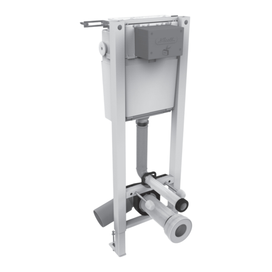
- Page 1 BÂTI-SUPPORT AVEC RÉSERVOIR DEUX VOLUMES ÉCONOMISEUR D’EAU Bâti-support mural WBS1PMU WBS1PMU110...
-
Page 2: Table Des Matières
SOMMAIRE DESCRIPTION ........................RÉGLAGES DES BÂTIS-SUPPORTS ..................POSE DES BÂTIS-SUPPORTS ....................MONTAGE DE LA PIPE ....................RÉGLAGE DES PIEDS ET DES ÉQUERRES ..............FIXATION ET RACCORDEMENT À L’ÉVACUATION ............FIXATION DE LA CUVETTE ....................RACCORDEMENT À L’ARRIVÉE D’EAU ................RÉALISATION DE L’HABILLAGE AVEC PLAQUE OU BOUTON DE COMMANDE ... COUPE DU TUBE DE RINÇAGE ET DU MANCHON D’ÉVACUATION ...... -
Page 3: Description
DESCRIPTION Support de robinet flotteur Robinet d’arrêt Ref. 0709399 Ref. 0709155 Robinet flotteur Ref. 0709398 Trappe Fixation murale Ref. 0709406 Ref. 0709404 Fixation murale Verrou mécanisme Ref. 0709404 Ref. 0709402 Mécanisme Ref. 0709325 Culot + joint Ref. 0709400 Coude de rinçage Kit fixation cuvette + joint Ref. -
Page 4: Réglages Des Bâtis-Supports
RÉGLAGE DES BÂTIS-SUPPORTS L’installation doit se faire sur un mur porteur. = 162 - 197 mm = 15 - 70 mm (plaque de commande) = 15 - 35 mm (bouton de commande) = 400 mm (recommandé si compatible avec votre cuvette) ou 450 mm pour personnes à... -
Page 5: Pose Des Bâtis-Supports
LA POSE DES BÂTIS-SUPPORTS MONTAGE DE LA PIPE Clipser la pipe sur son support. RÉGLAGE DES PIEDS ET DES ÉQUERRES Après avoir déterminé le bon réglage en hauteur, bloquer les vis pointeau, assembler, régler et fixer les équerres de fixation murales. RÉGLAGE DES PIEDS RÉGLAGE DES ÉQUERRES La position en hauteur de... -
Page 6: Fixation Et Raccordement À L'évacuation
LA POSE DES BÂTIS-SUPPORTS FIXATION ET RACCORDEMENT À L’ÉVACUATION Ajuster la pipe en recoupant la partie droite si besoin. Un manchon d’adaptation au diamètre de la canalisation peut-être nécessaire (non fourni). Présenter le bâti dans sa position définitive pour valider les réglages et pointer l’emplacement des perçages. -
Page 7: Fixation De La Cuvette
FIXATION DE LA CUVETTE Choisir l’entraxe des tiges de fixation. Positionner les 2 écrous M12 à embase en fonction de l’entraxe des tiges de fixation (180 ou 230 mm). Extrémité fendue de la tige du côté de la cuvette pour permettre l’ajustement à... -
Page 8: Raccordement À L'arrivée D'eau
LA POSE DES BÂTIS-SUPPORTS RACCORDEMENT DE L’ARRIVÉE D’EAU conseillé raccorder directement sur le robinet d’arrêt. Si utilisation d’un flexible (non fourni), les deux raccords aux extrémités du flexible doivent être à l’intérieur du réservoir par MOUSSE sécurité en cas de fuite. ISOLANTE L’arrivée d’eau peut se faire par la droite ou la gauche du réservoir en... -
Page 9: Réalisation De L'habillage
RÉALISATION DE L’HABILLAGE INSTALLATION AVEC PLAQUE DE COMMANDE Mettre en place le gabarit. Réaliser l’habillage à ras du gabarit. L’épaisseur de l’habillage ne doit pas excéder 70 mm. Ajouter des cales dans le cas de montage en cloison creuse double paroi. INSTALLATION AVEC BOUTON DE COMMANDE COUPE-FEU RÉF. - Page 10 LA POSE DES BÂTIS-SUPPORTS INSTALLATION AVEC BOUTON DE COMMANDE 403L / 404L / 405L Ø 40 mm 680 mm Prévoir une trappe d’accès au réservoir pour toute maintenance éventuelle. L’épaisseur de l’habillage ne doit pas excéder 35 mm sans rallonge et 90 mm avec rallonge.
-
Page 11: Après L'habillage
APRÈS L’HABILLAGE : Pour faciliter les opérations des étapes pages 11 et 12 : graisser les joints d’étanchéité de chaque raccord ou tube. COUPE DU TUBE DE RINÇAGE ET DU MANCHON D’ÉVACUATION Couper à X + 3 mm du bord Couper à... -
Page 12: Mise En Place De La Cuvette
LA POSE DES BÂTIS-SUPPORTS MISE EN PLACE DE LA CUVETTE Enfoncer le tube et le manchon sur le bâti à travers l’habillage. Mettre en place la cuvette sur les tiges de fixation. Attention, le montage de la cuvette sur une cloison creuse double paroi nécessite la pose de cales ou d’une plaque de renfort. -
Page 13: Installation De La Plaque De Commande
INSTALLATION DE LA PLAQUE DE COMMANDE COUPER LE GABARIT Couper le gabarit à l’aide d’un cutter afin de pouvoir mettre en place le cadre support. MISE EN PLACE DE PLAQUE DE COMMANDE Mise en place du cadre support : Séparer les vis du cadre, ébavurer la tête de vis et le cadre. - Page 14 LA POSE DES BÂTIS-SUPPORTS INSTALLATION DE LA PLAQUE DE COMMANDE FIXER LE BOUTON À L’AIDE DE L’ÉCROU Pour plus de détails, se reporter à la notice fournie avec le bouton de commande. RACCORDEMENT DU BOUTON DE COMMANDE Clipsage sur le bouton. Clic Verrouillage du boîtier de commande.
-
Page 15: Les Opérations De Maintenance
LES OPÉRATIONS DE MAINTENANCE... -
Page 17: Les Procédures D'entretien
LES PROCÉDURES D’ENTRETIEN 1. Fréquence d’entretien : En fonction de l’entartrage naturel du réseau et du réservoir avec un entretien annuel conseillé. 2. Étapes : a. couper l’arrivée d’eau, b. effectuer une grande chasse pour vider le réservoir, c. démonter le mécanisme et nettoyer le culot et son joint sans objet abrasif, d. - Page 18 LA POSE DES BÂTIS-SUPPORTS NOTES...
- Page 19 WALL FIXATION CONCEALED CISTERN EQUIPPED WITH A WATER SAVING DUAL FLUSH VALVE Support-frame WBS1PMU WBS1PMU110...
- Page 20 SUMMARY DESCRIPTION ........................SUPPORT FRAME ADJUSTMENT ..................INSTALLING THE SUPPORT FRAME ................INSTALLING THE ROTATING WC CONNECTOR ............ADJUSTING THE FRAMES ..................FIXING THE FRAME & CONNECTING THE DRAIN ............ATTACHING THE PAN ....................CONNECTING THE WATER INLET ................FITTING THE TILING WITH OPERATING PLATE OR PUSH BUTTON ......CUTTING THE WATER SUPPLY CONNECTOR AND SOIL AND WASTE SLEEVE ..
-
Page 21: Description
DESCRIPTION Float valve fixation Water supply - stop valve kit Ref. 0709399 Ref. 0709155 Float valve Ref. 0709398 Top door Wall fixations Ref. 0709406 Ref. 0709404 Wall fixations Flush valve fixation Ref. 0709404 Ref. 0709402 Flush valve Ref. 0709325 Sleeve+seal Ref. -
Page 22: Support Frame Adjustment
SUPPORT FRAME ADJUSTMENT The support frame has to be implemented on a hard wall = 162 - 197 mm = 15 - 70 mm (for operating plate) = 15 - 35 mm (for push button) = 400 mm (recommended when compatible with your pan) or 450 mm for disabled people 207 - 528... -
Page 23: Installing The Support Frame
INSTALLING THE SUPPORT FRAME INSTALLING THE CONNECTOR Clip the WC connector. ADJUSTING THE FEET & BRACKETS After adjusting to the right height, tighten the needle screws ; assemble and adjust the right hand brackets. FEET ADJUSTMENT BRACKET ADJUSTMENT The pan height position will be final. -
Page 24: Fixing The Frame & Connecting The Drain
INSTALLING THE SUPPORT FRAME FIXING THE FRAME AND CONNECTING THE DRAIN Adjust the connector by cutting the straight section, if necessary. An adapator pipe sleeve to fit the piping may be necessary (not supplied). Install the frame in its final position to validate the adjustments and mark where the holes are to be drilled. -
Page 25: Attaching The Pan
ATTACHING THE PAN Select the distance between the fastening rods. Position the 2 hexagonal flauge nuts according to the width between the threaded rods (180 or 230 mm). Put the slit end of the rod on the pan side to enable the adjusment with a screwdriver. -
Page 26: Connecting The Water Inlet
INSTALLING THE SUPPORT FRAME CONNECTING THE WATER INLET It is recommended to connect the water inlet directly to the stop cock. If a flexible tube is used (not supplied), the two fittings at both extemities of the flexible tube must be installed inside INSULATING the cistern for safety in case of a leak. - Page 27 FITTING THE TILLING INSTALLATION WITH OPERATING PLATE Install the polystyrene template. Place tiling flush with template. The tiling thickness must NOT exceed 70 mm. If implementation in hollow wall, don’t forget to add shim. INSTALLATION WITH PUSH BUTTON FIREWALL CONTROL BUTTON REF.: WBCCFB / WBCCFC / WBCCFS Ø...
- Page 28 INSTALLING THE SUPPORT FRAME INSTALLATION WITH PUSH BUTTON 403L / 404L / 405L Ø 40 mm 680 mm Don’t forget to plan an Plan a 40 mm diameter hole to access hatch in case of any install the push button. maintenance operations.
-
Page 29: Cutting The Water Supply Connector And Soil And Waste Sleeve
AFTER TILING: To facilitate the operations described pages 29 and 30 apply some grease to the seals of each fitting or tube. CUTTING THE WATER SUPPLY CONNECTOR AND SOIL AND WASTE SLEEVE Cut to X + 3 mm from the edge Cut to Y + 3 mm... -
Page 30: Installing The Pan
INSTALLING THE SUPPORT FRAME INSTALLING THE PAN Push the tube and sleeve onto the frame through the tiling. Install the pan on the fastening rods. -
Page 31: Installing The Operating Plate
INSTALLING THE OPERATING PLATE CUTING THE TEMPLATE Cut the template to install the support frame for the operating plate. INSTALLING THE SUPPORT FRAME Install the support frame: Remove the screws from the frame, fettle the screw head and the frame. Insert the screws slanted as shown on the drawing. -
Page 32: Installing The Push Button
INSTALLING THE SUPPORT FRAME INSTALLING THE PUSH BUTTON INSTALL THE BUTTON WITH THE NUT CONNECTION OF THE PUSH BUTTON TO THE MECHANISM Clip onto the push button. Clic Lock the clip to the button. -
Page 33: Maintenance Operations
MAINTENANCE OPERATIONS... -
Page 35: Maintenance Procedure
MAINTENANCE PROCEDURES 1. Maintenance frequency: depending on natural limescale with a recommended yearly maintenance. Steps: a. turn off the water supply, b. empty the tank by flushing, c. disassemble the flush valve and clean up the sleeve and the seal without an abrasive object, d. - Page 36 52 - 54 - 55 - 57 - 58 - 67 56 - 61 - 72 - 79 - 85 - 86 92 - 93 - 94 - 95 68 - 70 - 71 - 88 - 89 - 90 sivouest.nicoll@aliaxis.com sivnordidf.nicoll@aliaxis.com sivest.nicoll@aliaxis.com SUD-EST SUD-OUEST RHÔNE-ALPES AUVERGNE...