
Manuels Connexes pour Steinberg 390 4221 1


Sommaire des Matières pour Steinberg 390 4221 1
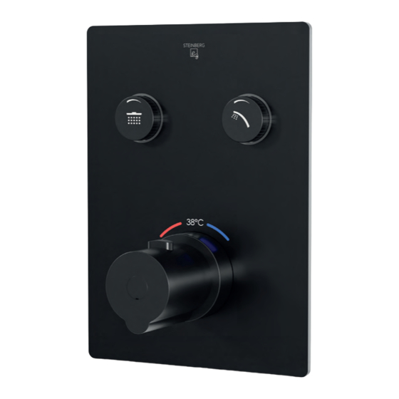
- Page 1 PUSH TRONIC DEUTSCH ENGLISH FRANÇAIS 390 4221 1 | 390 4231 1 | 390 4321 1 |390 4221 1 S...
-
Page 2: Lieferumfang
LIEFERUMFANG ITEMS SUPPLIED | CONTENU DE LA LIVRAISON 390 4221 1 S 390 4221 1 390 4231 1 390 4321 1... - Page 3 13. Befestigungsschlüssel für Spannhülsen Concealed thermostatic mixer Fixing tool for clamping sleeves Mélangeur thermostatique Clé de fixation pour douilles de serrage A: 390 4221 1 S | B: 390 4221 1 C: 390 4231 1 | D: 390 4321 1...
-
Page 4: Technische Zeichnung
TECHNISCHE ZEICHNUNG DIMENSIONS | DIMENSIONS 390 4221 1 (S) 85 ~ 105 60 ~ 80 G1/2" G3/4" 390 4221 1 85 ~ 105 60 ~ 80 G1/2" G3/4"... - Page 5 4 Buttons im Lieferumfang enthalten / 4 buttons included / 4 boutons inclus...
- Page 6 TECHNISCHE ZEICHNUNG DIMENSIONS | DIMENSIONS 390 4231 1 85 ~ 105 60 ~ 80 G1/2" G1/2" G3/4" 390 4231 1 85 ~ 105 60 ~ 80 G1/2" G1/2" G3/4"...
- Page 7 4 Buttons im Lieferumfang enthalten / 4 buttons included / 4 boutons inclus...
- Page 8 TECHNISCHE ZEICHNUNG DIMENSIONS | DIMENSIONS 390 4321 1 85 ~ 105 60 ~ 80 G1/2" G3/4" 3,60 390 4321 1 85 ~ 105 60 ~ 80 G1/2" G3/4" 3,60...
- Page 9 4 Buttons im Lieferumfang enthalten / 4 buttons included / 4 boutons inclus...
-
Page 10: Informations Générales
MONTAGEANLEITUNG INSTALLATION INSTRUCTIONS | GUIDE D‘INSTALLATION Allgemein Die Montageanleitung beinhaltet Vorgaben für die vorschriftsgemäße Installation der Pushtronic. Die Produktgarantie erlischt, wenn das Produkt nicht gemäß der Montageanleitung installiert wird. Die Montage ist nur durch qualifizierte Sanitärinstallations-Fachbetriebe unter Beachtung dieser Montageanleitung und den länderspezifisch geltenden Normen, Regelungen und Sicherheits- bestimmungen zulässig. - Page 12 MONTAGEANLEITUNG INSTALLATION INSTRUCTIONS | GUIDE D‘INSTALLATION Anschließend Leitungen spülen. Variable Anordnung der Anschlüsse und Buttons. Rinse piping after installation. Outlets and push buttons may be arranged freely. Rincer ensuite la tuyauterie. Disposition flexible des boutons poussoirs. Les sorties et les boutons poussoirs peuvent êtres disposés librement.
- Page 13 Dichtheitsprüfung bei 16 Bar Die Schalterstellung wird durch leichtes Wackeln an den Spannhülsen festgestellt: Spannhülse lose = Ventil geschlossen Spannhülse fest = Ventil offen Leakproofness test at 16 bar Identify On/Off position by slightly wiggling the clamping sleeves: Clamping sleeve loose = valve closed Clamping sleeve tight = valve open Test d‘étanchéité...
- Page 14 MONTAGEANLEITUNG INSTALLATION INSTRUCTIONS | GUIDE D‘INSTALLATION Bitte Montagemaß beachten! Grün = Nutzbarer Einbaubereich bis Vorderkante Fertigwand Rot = Außerhalb des vorgeschriebenen Einbaumaßes, bitte vermeiden/korrigieren Please note clearance requirements: Green = usable space up to face of finished wall /tiling Red = outside tolerance – make sure to avoid or correct S‘il vous plaît prêter attention à...
- Page 16 MONTAGEANLEITUNG INSTALLATION INSTRUCTIONS | GUIDE D‘INSTALLATION 10.1 10.2 Für die korrekte Montage der Schubrosette die Schrauben und Spannhülsen bis zur jeweiligen Kante der Montage hilfe drehen (Spannhülse fest). Wenn nötig die anderen werksseitig gelieferten Spann hülsen/ Übergangsstücke und Schrauben verwenden. (Abb. 9, 10, 10.1, 10.4, 10.5) Before applying cover plate, turn bolds and clamping sleeves to be even with respective edge of fixing template (clamping sleeves tight).
- Page 17 10.3 10.4 10.5...
- Page 18 MONTAGEANLEITUNG INSTALLATION INSTRUCTIONS | GUIDE D‘INSTALLATION Schutzkappe abziehen und Rosette aufschieben, dann Buttons auf die Spannhülsen drücken. Remove protective sheath and apply cover plate. Press control buttons onto respective clamping sleeve. Poussez la plaque de recouvrement sur le corps et poussez les boutons en appuyant sur les douilles de serrage.
- Page 19 Im eingeschalteten Zustand müssen die Bedienknöpfe 7–9 mm aus der Abdeckung hervorstehen. In On position, control buttons must protrude by 7–9 mm from cover plate. En position ouvert, les boutons de commande doivent dépasser de 7 à 9 mm du plaque de recouvrement.
- Page 20 R AIN STEINBERG GmbH Schiess-Str. 30 D-40549 Düsseldorf Tel. +49 (0)211 520 249-0 Fax: +49 (0) 211 520 249 -20 info@steinberg-armaturen.de www.steinberg-armaturen.de Der Hersteller behält sich das Recht vor, ohne vorherige Ankündigung technische Änderungen vorzunehmen. The manufacturer reserves the right to make technical modifications without prior notice.