Table des Matières
Publicité
Les langues disponibles
Les langues disponibles
Liens rapides
Publicité
Table des Matières

Manuels Connexes pour Chauvin Arnoux Multimetrix CM 605


Sommaire des Matières pour Chauvin Arnoux Multimetrix CM 605
- Page 1 PINCE MULTIMÈTRE CLAMP MULTIMETER VIELFACHMESSZANGE PINZA MULTIMETRO PINZA MULTIMMETRICA CM 605 FRANÇAIS Notice de fonctionnement ENGLISH User’s manual DEUTSCH Bedienungsanleitung ITALIANO Libretto d’istruzioni ESPAÑOL Manual de instrucciones...
- Page 2 Français ..................... 3 English ....................9 Deutsch .................... 15 Italiano ....................22 Español .................... 28...
-
Page 3: Conditions Generales De Garantie Et De Securite
CONDITIONS GENERALES DE GARANTIE ET DE SECURITE 1. PRECAUTIONS D’EMPLOI Lisez les instructions de sécurité ci-dessous avant toute utilisation de l’appareil, afin d’éviter les accidents corporels, tels que brûlures et chocs électriques. Suivez impérativement les indications précédées du symbole 1.1 CATÉGORIES DE MESURE (CF EN 61010-2-033) CATÉGORIE DE MESURE II La CATEGORIE DE MESURE II est applicable aux circuits de test et de... -
Page 4: Pour Travailler En Securite
1.3 EXPLICATIF DES SYMBOLES Symbole Signification Symbole Signification Instrument à double Fusible. isolation. Courant alternatif. Homologation CE. Courant continu. Conformément à la directive WEEE 2002/96/EC Attention. Se référer Ne pas appliquer ou aux instructions enlever sur des d’utilisation. conducteurs sous Terre. -
Page 5: Garantie
2. GARANTIE Ce matériel est garanti contre tout défaut de matière ou vice de fabrication, conformément aux conditions générales de vente. Durant la période de garantie, l'appareil ne peut être réparé que par le constructeur, celui-ci se réservant la décision de procéder soit à la réparation, soit à l'échange de tout ou partie de l'appareil. -
Page 6: Utilisation
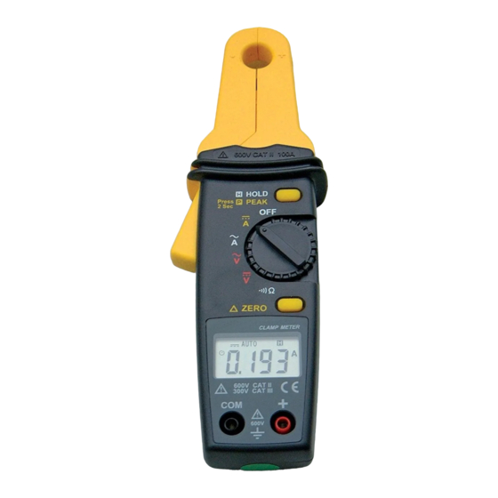
UTILISATION 6. PRESENTATION 6.1 LA FACE AVANT Rep. Fonction Borne négative noire (-) COM. Afficheur à cristaux liquides: 4 digits (9999 points). ‘OL’ : dépassement de capacité en mesure de courant et tension. Gâchette d’ouverture de la pince. Garde : la main doit toujours se trouver à l’arrière de cette protection durant la mesure. -
Page 7: Mesure De Tension
7.3 MESURE DE TENSION Lisez les recommandations de sécurité avant utilisation. Gammes de mesure automatiques 600 V DC ou AC. Positionner le sélecteur (rep. 8) sur : pour mesurer une tension continue. pour mesurer une tension alternative. Insérer le connecteur noir dans la borne COM (rep. 1), le rouge dans la borne + (rep. -
Page 8: Sortie Signal Analogique
7.7 TEST DE CONTINUITE Lisez les recommandations de sécurité avant utilisation. Le circuit sera impérativement hors-tension. Positionner le sélecteur (rep. 8) sur Insérer le cordon noir dans la borne COM (rep. 1), le rouge dans la borne + (rep. 10) et appliquer les pointes de touche sur le circuit à... -
Page 9: Caracteristiques
9. CARACTERISTIQUES 9.1 GENERALES Mesure des valeurs Tensions continues, tensions alternatives, courant continu, courant alternatif, résistance, test de continuité. Afficheur 4 digits (9 999 points) Polarité Indication signe « - ». Gammes Sélection automatique. Fonctions Arrêt automatique (ON ou OFF). additionnelles Affichage de dépassement de capacité... -
Page 10: Precautions During Use
GENERAL SAFETY AND GUARANTEE CONDITIONS 1. PRECAUTIONS DURING USE Please read the safety instructions below before using the instrument to avoid any accidental injuries, such as burns or electric shocks. You must observe the instructions preceded by the symbol 1.1 MEASUREMENT CATEGORIES (EN 61010-2-033) MEASUREMENT CATEGORY II MEASUREMENT CATEGORY II is applicable to test and measuring... -
Page 11: Explanation Of The Symbols
1.3 EXPLANATION OF THE SYMBOLS Symbol Signification Symbol Signification Instrument with Fuse. double insulation. Alternating current CE approved. (AC). Direct current (DC). According to WEEE directive 2002/96/EC Warning! Please refer Do not apply around to the operating or remove from instructions. -
Page 12: Unpacking And Repacking
Improper use of the instrument or its use with incompatible equipment. Modification of the instrument without express authorisation from the manufacturer’s technical departments. Any work being performed on the instrument by anyone not formally approved by the manufacturer. ... - Page 13 6. INTRODUCTION 6.1 THE FRONT FACE Function Black Negative COM terminal (-). Liquid crystal display 4 digits (9999 points). ‘OL’: current and voltage measurements exceed the range. Trigger for opening the clamp. Guard: Your hand must be behind this protective guard. Movable jaws.
- Page 14 7.3 TO MEASURE VOLTAGE Please read the safety recommendations before use. Automatic measurement ranges 600V DC or AC. Set the selector (8) on: to measure a DC voltage. to measure an AC voltage. Insert the black connector into the COM terminal (1), the red connector into the + terminal (10) and take the voltage reading once it has stabilised.
-
Page 15: Continuity Test
7.7 CONTINUITY TEST Please read the safety recommendations before use. There must be no voltage in the circuit. Set the selector (8) to Insert the black cable in the COM terminal (1), the red cable in the + terminal (10) and apply the contact points to the circuit to be checked. -
Page 16: Technical Details
9. CHARACTERISTICS 9.1 GENERAL Value measurements DC and AC voltages, AC and DC current, resistance, continuity test. Display 4 digits (9 999 points) Polarity indication “ – “ sign. Ranges Automatic range selection. Additional selectable Automatic shutdown (active or not). functions Display of capacity being exceeded Maximum measurement (Peak). -
Page 17: Vorsichtsmassnahmen Beim Gebrauch
ALLGEMEINE GARANTIEBEDINGUNGEN UND SICHERHEITSHINWEISE 1. VORSICHTSMASSNAHMEN BEIM GEBRAUCH Lesen Sie die folgenden Sicherheitsanweisungen vor dem Gebrauch des Gerätes, um Verletzungen wie Verbrennungen und Stromschläge zu vermeiden. Alle mit diesem Symbol gekennzeichneten Anweisungen müssen unbedingt beachtet werden. 1.1 MESSKATEGORIEN (EN 61010-2-033) MESSKATEGORIE II Die MESSKATEGORIE II bezieht sich auf Prüf- und Messkreise, die direkt Verbrauchsstellen... -
Page 18: Erklärung Der Symbole
1.3 ERKLÄRUNG DER SYMBOLE Instrument mit Sicherung. doppelter Isolierung. Wechselstrom. EG-Zulassung. Gleichstrom. Entsprechend der Richtlinie WEEE 2002/96/EC Achtung. Lesen Sie in Nicht an unter gefährlicher Bedienungsanleitung Spannung stehende nach. Leiter anschließen bzw. von diesen trennen Erdung. 1.4 SICHERES ARBEITEN Dieses Symbol gilt für den gesamten Absatz. ... -
Page 19: Messtechnische Überprüfung
Es wird mindestens eine einmal jährlich durchgeführte Überprüfung dieses Gerätes empfohlen. Für Überprüfung und Kalibrierung wenden Sie sich bitte an unsere zugelassenen Messlabors (Auskunft und Adressen auf Anfrage), bzw. an die Chauvin Arnoux Niederlassung oder den Händler in Ihrem Land. 4.2 REPARATUR Senden Sie das Gerät bei Reparaturen innerhalb und außerhalb der... - Page 20 GEBRAUCH 6. PRÄSENTATION 6.1 DIE VORDERSEITE Abb. Funktion Negative schwarze Anschlussklemme (-) COM. LCD – Anzeigegerät 4 Ziffern (9.999 Punkte). ‘OL’: Bereichsüberschreitung bei der Strom- und Spannungsmessung. Taste zum Öffnen der Zange. Schutzring: Die Hand muss hinter diesem Schutz liegen Bewegliche Zangenbacke.
- Page 21 Annullieren der Selbstsperrung Bitte stellen Sie den Auswahlknopf (Abb. 8) auf OFF. Halten Sie bitte die Taste ZERO (Abb. 9) gedrückt und drehen Sie nun den Auswahlknopf (Abb. 8) auf eine andere Position als OFF. Das Symbol erlischt; die Selbstsperrung ist nun deaktiviert. Wiedereinschalten der Selbstsperrung Bitte stellen Sie den Auswahlknopf (Abb.
- Page 22 7.5 MESSUNG DES WECHSELSTROMES Automatische Messbereiche von A0 A AC bis 100 A AC (3 Bereiche). Bitte stellen Sie den Auswahlknopf (Abb. 8) auf Betätigen Sie bitte den Handgriff (Abb. 3), um die Klemme (Abb. 6) zu öffnen und setzen Sie nun einen Leiter in der Mitte der Klemme ein.
-
Page 23: Funktion Max (Anzeige Des Höchstwertes)
7.9 FUNKTION MAX (ANZEIGE DES HÖCHSTWERTES) Bitte stellen Sie den Auswahlknopf auf betätigen Sie nun die Taste HOLD (Abb. 7) während der Messung bis zur Anzeige des Symbols (Abb. 17). Führen Sie nun bitte die Messung durch. Die Höchstmessung wird automatisch aktualisiert. Für die Deaktivierung der Funktion , bitte die Taste HOLD (Abb. - Page 24 9. EIGENSCHAFTEN 9.1 ALLGEMEINES Wertemessung Gleichspannung, Wechselspannung, Wechselstrom, Gleichstrom, Widerstand, Test des Stromflusses. Anzeigegerät 4 Ziffern (9 999 Punkte). Angabe der Polarität Zeichen „ – “. Bereiches Auswahl des automatischen Bereiches. Zusätzliche Selbstsperrung (aktiviert oder auswählbare deaktiviert). Funktionen Anzeige der Bereichsüberschreitung Höchstmessung (Max Hold).
-
Page 25: Avvertenze Per L'uso
CONDIZIONI GENERALI DI GARANZIA E SICUREZZA 1. AVVERTENZE PER L’USO Leggere le seguenti istruzioni di sicurezza prima di qualsiasi uso dell’apparecchio, per evitare incidenti fisici quali bruciature e scosse elettriche. Le disposizioni precedute dal simbolo vanno rigorosamente rispettate. 1.1 CATEGORIE DI MISURA (EN 61010-2-033) CATEGORIA DI MISURA II La CATEGORIA DI MISURA II è... -
Page 26: Spiegazione Dei Simboli
1.3 SPIEGAZIONE DEI SIMBOLI Symbole Signification Symbole Signification Strumento a doppio Fusibile. isolamento. Corrente alternata. Omologazione CE. Corrente continua. In conformità alla direttiva WEEE 2002/96/EC. Attenzione. Fare Non applicare o riferimento alle togliere su conduttori istruzioni per l’uso. in tensione periocolosa. -
Page 27: Disimballaggio E Reimballaggio
Vi consigliamo almeno una verifica annuale dello strumento. Per le verifiche e le calibrazioni, rivolgetevi ai nostri laboratori di metrologia accreditati (informazioni e recapiti su richiesta), alla filiale Chauvin Arnoux del Vostro paese o al vostro agente. 4.2 RIPARAZIONE Per qualsiasi intervento da effettuare in o fuori garanzia, si prega d’inviare... -
Page 28: Lato Anteriore
UTILIZZO 6. PRESENTAZIONE 6.1 LATO ANTERIORE Fig. Funzione Terminale negativo nero (-) COM. Visore a cristalli liquidi 4 cifre (9999 punti). ‘OL : superamento capacità nella misurazione di corrente e tensione. Nottolino di apertura della pinza. Attenzione : la mano deve trovarsi dietro tale protezione. - Page 29 Annullare l’arresto automatico Posizionare il selettore (fig. 8) su OFF. Tenere premuto il tasto ZERO (fig. 9) e girare il selettore (fig. 8) su una posizione diversa da OFF. Scompare l’icona e l’arresto automatico viene disattivato. Riavviare l’arresto automatico Posizionare il selettore (fig. 8) su OFF. Posizionare il selettore (fig.
-
Page 30: Misurazione Di Resistenza
7.6 MISURAZIONE DI RESISTENZA Leggere le disposizioni di sicurezza prima dell’uso. Il circuito deve essere obbligatoriamente fuori tensione. Gamme di misurazioni automatiche : 0 - 10 kΩ (1 gamme). Posizionare il selettore (fig. 8) su Inserire il cavo nero nel terminale COM (fig. 1) e il cavo rosso nel terminale + (fig. -
Page 31: Sostituzione Delle Pile
8. SOSTITUZIONE DELLE PILE Leggere le disposizioni di sicurezza prima dell’uso. Il circuito deve essere obbligatoriamente fuori tensione. Sostituire le pile quando compare l’icona (fig. 13) : Scollegare i puntali di tasto. Posizionare il commutatore su OFF. Togliere vite di fissaggio e coperchio di alloggiamento pile. Sostituire le 2 pile 1,5 V (AAA) rispettando le polarità. -
Page 32: Precauciones De Uso
CONDICIONES GENERALES DE GARANTÍA Y DE SEGURIDAD 1. PRECAUCIONES DE USO Lea las siguientes instrucciones de seguridad antes de utilizar el aparato, con el fin de evitar los accidentes corporales, como quemaduras y electrocuciones. Respete obligatoriamente las indicaciones precedidas del símbolo 1.1 CATEGORÍAS DE MEDIDA (EN 61010-2-033) CATEGORÍA DE MEDIDA II La CATEGORÍA DE MEDIDA II se aplica a los circuitos de prueba y... - Page 33 1.3 EXPLICACIONES DE LOS SÍMBOLOS Symbole Signification Symbole Signification Instrumento de doble Fusible. aislamiento. Corriente alterna. Homologación CE. Corriente continua. Conforme a la directiva WEEE 2002/96/EC. Atención. Consultar No colocar sobre, o las instrucciones de retirar de conductores uso. vivos sometidos a tensiones peligrosas.
-
Page 34: Desembalaje Y Re-Embalaje
Para las verificaciones y calibraciones, póngase en contacto con nuestros laboratorios de metrología acreditados (solicítenos información y datos), con la filial Chauvin Arnoux o con el agente de su país 4.2 REPARACIÓN Para las reparaciones ya sean en garantía o fuera de garantía, devuelva el instrumento a su distribuidor. - Page 35 UTILIZACIÓN 6. PRESENTACIÓN 6.1 LA FRONTAL Marca. Función Borne negativo negro (-) COM. Pantalla de cristales líquidos 4 dígitos (4369 puntos). ‘OL‘: superación de la capacidad de medición de corriente y tensión. Gatillo de apertura de la pinza. Protección: la mano debe encontrarse detrás de esta protección.
-
Page 36: Medición De Tensión
Reanudar el apagado automático Posicionar el selector (marca 8) sobre OFF. Posicionar el selector sobre una posición que no sea OFF. El icono aparece; el apagado automático está activado. 7.3 MEDICIÓN DE TENSIÓN Lea las recomendaciones de seguridad antes de utilizar. Gamas de medición automáticas 600 V DC / AC Posicionar el selector (marca 8) sobre el símbolo : para medir una tensión continua. -
Page 37: Test De Continuidad
7.7 TEST DE CONTINUIDAD Lea las recomendaciones de seguridad antes de utilizar. El circuito estará obligatoriamente fuera de tensión. CM 610: posicionar el selector (marca 8) sobre Insertar el cable negro en el borne COM (marca 1), el rojo en el borne + (marca 10) y aplicar las puntas sobre el circuito a controlar. -
Page 38: Características
9. CARACTERÍSTICAS 9.1 GENERALES Medición de los Tensiones continuas, tensiones valores alternas, corriente alterna, corriente continua, resistencia, test de continuidad. Pantalla 4 dígitos (9 999 puntos). Indicación de polaridad Signo “-”. Gama Selección de gama automática. Funciones adicionales Apagado automático (activo o no). seleccionables Visualización de superación de capacidad (OL). - Page 39 Range 10 A /80 A / 80-100 A 50 → 500 Hz Resolution (mA) 1/10/10 Accuracy ±2% + 10 dgt ±2% +10 dgt ±3.5% + 10 dgt Iin max 150 A RMS Range 10 A / 80 A / 80-100 A Resolution 1 mA / 10 mA / 10 mA Accuracy...
- Page 40 Hongkou District - 200081 SHANGHAI Tel: +86 21 65 21 51 96 - Fax: +86 21 65 21 61 07 USA - Chauvin Arnoux Inc - d.b.a AEMC Instruments SCANDINAVIA - CA Mätsystem AB Sjöflygvägen 35 - SE 18304 TÄBY 200 Foxborough Blvd.