Table des Matières
Publicité
Les langues disponibles
Les langues disponibles
Liens rapides
IB507001EN
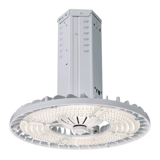
Installation Instructions – Steeler LED
Instructions d'installation – DEL Steeler
Instrucciones de instalación – LED Steeler
WARNING
Risk of fire, electrical shock, cuts and or other casualty
hazards. This product must be installed in accordance
with the applicable installation code by a qualified
electrician or a person familiar with the construction
and operation of the product and the hazards involved.
Eaton assumes no responsibility for claims brought
about by improper or careless installation or handling
of this product.
WARNING
Risk of Fire and Electric Shock. If not qualified, consult
an electrician.
IMPORTANT: Read carefully before installing fixture. Retain for future reference.
ATTENTION Receiving Department: Note actual fixture description of any shortage or noticeable damage on delivery
receipt. File claim for common carrier (LTL) directly with carrier. Claims for concealed damage must be filed within 15
days of delivery. All damaged material, complete with original packing must be retained.
INSTALLATION
Pendant Mount
1.
Insert incoming power to Quick disconnect, wire
according to code (Figure 1).
2.
Mount fixture to 3/4" NPT threaded hub and fasten
screw to lock (Figure 2).
CAUTION
Edges May Cut. Handle with care.
CAUTION
Risk of burn. Disconnect power and allow fixture to cool
before changing bulb or handling fixture.
NOTICE: Minimum 90° supply conductors.
NOTE: Specifications and dimensions subject to change
without notice.
Ground wire
3/4" NPT
threaded hub
Figure 1.
Figure 2.
Brand Logo
reversed out of
black
INS #
INS #
3/4" NPT threaded pipe
Quick
Disconnect
Locking
screw
Publicité
Table des Matières

Sommaire des Matières pour Eaton Metalux SSLED-LD1-12-W-UNV-L840-CD1-U
- Page 1 Risk of burn. Disconnect power and allow fixture to cool Eaton assumes no responsibility for claims brought before changing bulb or handling fixture. about by improper or careless installation or handling NOTICE: Minimum 90°...
- Page 2 Top cover Top connector Figure 3. Connector box cover Figure 7. Top cover Figure 4. 3/4” NPT threaded hub or hook Figure 8. J Box (Supplied by others) Locking screw Figure 9. Figure 5. EATON IB507001EN Installation instructions...
- Page 3 Identify violet and gray leads of each driver. Remove K.O. & Wire circuit through the hole (Figure 11). Close driver compartment (Figure 12). Ground wire To Dimming circuit Figure 11. Driver bracket To Dimming circuit Figure 10. To AC circuit Figure 12. EATON IB507001EN Installation instructions...
-
Page 4: Important
Risque de brûlures. Mettez l’alimentation électrique hors tension ainsi qu'avec les risques inhérents. Eaton n'assume aucune responsabilité pour les réclamations provenant et laissez refroidir le luminaire avant de le manipuler ou de de l'installation ou de la manipulation incorrecte ou changer l'ampoule. -
Page 5: Installation Du Cordon
Figure 7. Figure 4. Entrée ou crochet fileté NPT de 1,27 cm (3/4 po) Figure 8. Vis de blocage Boîte de jonction (non fournie) Figure 5. Figure 9. Couvercle du boîtier Couvercle du connecteur supérieur Figure 6. EATON IB507001EN Instructions d’installation... -
Page 6: Installation De Circuit De Gradation
(Figure 11). Fil de mise à la terre Fermez le compartiment du régulateur (Figure 12). Au circuit de gradation Figure 11. Support du régulateur Au circuit de gradation Figure 10. Au circuit de courant alternatif Figure 12. EATON IB507001EN Instructions d’installation... - Page 7 Riesgo de quemadura. Desconecte la energía y deje enfriar la instalación aplicable. Eaton no se responsabiliza por luminaria antes de manipularla o cambiar la bombilla. los reclamos presentados respecto de la instalación AVISO: Conductores de alimentación de 90°...
-
Page 8: Instalación Del Cable
Figura 7. Figura 4. Gancho o lazo roscado NPT de 3/4” Figura 8. Tornillo de sujeción Caja de derivación (de otras marcas) Figura 5. Figura 9. Cubierta de la caja Cubierta del conector superior Figura 6. EATON IB507001EN Instrucciones de instalación... - Page 9 (Figura 11). Desconexión Cierre el compartimento del controlador (Figura 12). Al circuito del rápida regulador Figura 11. Al circuito del regulador Soporte del controlador Al circuito de CA Figura 10. Figura 12. EATON IB507001EN Instrucciones de instalación...
-
Page 12: Garanties Et Limitation De Responsabilité
Warranties and Limitation of Liability Please refer to www.eaton.com/LightingWarrantyTerms for our terms and conditions. Garanties et limitation de responsabilité Veuillez consulter le site www.eaton.com/LightingWarrantyTerms pour obtenir les conditions générales. Garantías y Limitación de Responsabilidad Visite www.eaton.com/LightingWarrantyTerms para conocer nuestros términos y condiciones.


