Table des Matières

Manuels Connexes pour afriso PrimoTherm K 180-1

Sommaire des Matières pour afriso PrimoTherm K 180-1
- Page 1 Betriebsanleitung Operating instructions Notice technique Instrukcja eksploatacji PrimoTherm® Copyright 2021 AFRISO-EURO-INDEX GmbH. Alle Rechte vorbehalten. Version: 09.2021.0 ID: 900.000.0973...
- Page 2 Betriebsanleitung Heizungspumpengruppe PrimoTherm® Typ: K 180-1 DN 32 ohne Mischer Typ: K 180-2 DN 32 mit 3-Wege-Mischer und Stellmotor Copyright 2021 AFRISO-EURO-INDEX GmbH. Alle Rechte vorbehalten. Version: 09.2021.0 ID: 900.000.0973...
- Page 3 Über diese Betriebsanleitung Über diese Betriebsanleitung Diese Betriebsanleitung beschreibt die Heizungspumpengruppen PrimoT- herm® „K 180-1 DN 32“ und „K 180-2 DN 32“ (im Folgenden auch „Pro- dukt“). Diese Betriebsanleitung ist Teil des Produkts. • Sie dürfen das Produkt erst benutzen, wenn Sie die Betriebsanleitung vollständig gelesen und verstanden haben.
- Page 4 Informationen zur Sicherheit Informationen zur Sicherheit Warnhinweise und Gefahrenklassen In dieser Betriebsanleitung finden Sie Warnhinweise, die auf potenzielle Gefahren und Risiken aufmerksam machen. Zusätzlich zu den Anweisungen in dieser Betriebsanleitung müssen Sie alle am Einsatzort des Produktes geltenden Bestimmungen, Normen und Sicherheitsvorschriften beachten. Stellen Sie vor Verwendung des Produkts sicher, dass Ihnen alle Bestimmun- gen, Normen und Sicherheitsvorschriften bekannt sind und dass sie befolgt werden.
-
Page 5: Informationen Zur Sicherheit
Informationen zur Sicherheit Zusätzlich werden in dieser Betriebsanleitung folgende Symbole verwendet: Dies ist das allgemeine Warnsymbol. Es weist auf die Gefahr von Verletzungen und Sachschäden hin. Befolgen Sie alle im Zusammenhang mit diesem Warnsymbol beschriebenen Hinweise, um Unfälle mit Todesfolge, Verlet- zungen und Sachschäden zu vermeiden. -
Page 6: Vorhersehbare Fehlanwendung
Informationen zur Sicherheit Vorhersehbare Fehlanwendung Das Produkt darf insbesondere in folgenden Fällen und für folgende Zwecke nicht angewendet werden: • Betrieb mit Trinkwasser • Betrieb mit verklebenden, ätzenden oder entzündlichen Medien • Betrieb mit Dampf, ölhaltigen und aggressiven Medien • Betrieb in Anlagen mit Temperaturen über 110 °C (beispielsweise Solar- anlagen) •... -
Page 7: Transport Und Lagerung
Transport und Lagerung Transport und Lagerung Das Produkt kann durch unsachgemäßen Transport und Lagerung beschä- digt werden. HINWEIS UNSACHGEMÄSSE HANDHABUNG • Stellen Sie sicher, dass während des Transports und der Lagerung des Pro- dukts die spezifizierten Umgebungsbedingungen eingehalten werden. • Benutzen Sie für den Transport die Originalverpackung. - Page 8 Produktbeschreibung Produktbeschreibung Das Produkt ist eine vormontierte, dichtheitsgeprüfte und wärmegedämmte Heizungspumpengruppe, die den Einbau handelsüblicher Pumpen DN 32 (mit dem Anschluss G2 und einer Baulänge von 180 mm) ermöglicht. Der Vorlauf kann wahlweise links oder rechts angeordnet werden. Optional kön- nen in allen Kugelhähnen Temperaturfühler montiert werden.
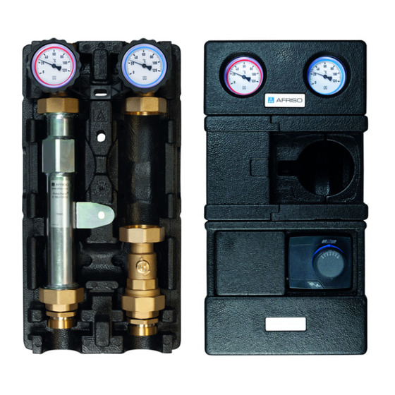
- Page 9 Produktbeschreibung 1. Rücklauf 2. Vorlauf A. Kugelhahn, absperrbar, mit Thermometer blau B. Kugelhahn, absperrbar, mit Thermometer rot C. Raum für optionale Umwälzpumpe D. 3-Wege-Mischer mit Stell- motor E. Wärmedämmung Abbildung 2: PrimoTherm® K 180-2 Vario mit 3-Wege-Mischer und Stellmotor PrimoTherm®...
- Page 10 Produktbeschreibung Wärmedämmung Die obere Schale der Wärmedämmung besteht aus vier Teilen. Die Teile kön- nen einzeln abgenommen werden. 1. Beachten Sie die Richtung beim Abnehmen der Wärmedämmung. A. Oberes Dämmungsteil C. Unteres Dämmungsteil B. Mittlere Dämmungsteile Abbildung 3: Teile der Wärmedämmung PrimoTherm®...
-
Page 11: Abmessungen Und Anschlüsse
Produktbeschreibung Abmessungen und Anschlüsse 248 mm 170 mm 197 mm Abbildung 4: Abmessungen PrimoTherm® K 180-1 und K 180-2 (mit Mischer) PrimoTherm®... - Page 12 Produktbeschreibung ca. 60 mm A. G1¼i B. Überwurfmuttern und Flachdichtungen (für Pumpeneinbau) C. G2a D. Verschraubungsset E. Verschraubung für Wand- montage G1¼i F. Verschraubung für die Montage auf dem Kessel- verteiler G1½a Abstandsmaße von der Unterkante der Wärmedäm- mung bis zum Anschluss bei montiertem Zubehör.
- Page 13 Produktbeschreibung ca. 60 mm A. G1¼i B. Überwurfmuttern und Flachdichtungen (für Pumpeneinbau) C. G2a D. Verschraubungsset E. Verschraubung für Wand- montage G1¼i F. Verschraubung für die Montage auf dem Kessel- verteiler G1½a Abstandsmaße von der Unterkante der Wärmedäm- mung bis zum Anschluss bei montiertem Zubehör.
-
Page 14: Zulassungsdokumente, Bescheinigungen, Erklärungen
Produktbeschreibung Funktion Variante K 180-1 DN 32 Das Produkt wird in ungemischten Heizkreisen, speziell auch zur Speicher- ladung verwendet. Der zusätzliche Kugelhahn unterhalb der Umwälzpumpe ermöglicht einen Tausch der Umwälzpumpe, ohne die Anlage zu entleeren. Variante K 180-2 DN 32 Das Produkt hat zusätzlich einen 3-Wege Mischer zur Vorlauftemperaturre- gelung sowie einen Stellmotor. -
Page 15: Technische Daten
Produktbeschreibung Technische Daten Parameter Wert Allgemeine Daten Abmessungen mit Wärme- 248 x 480 x 170 mm dämmung (B x H x T) Gewicht K 180-1 DN 32 Ca. 5,5 kg ohne Umwälzpumpe Gewicht K 180-2 DN 32 Ca. 7,0 kg ohne Umwälzpumpe Werkstoff Armaturen Messing, Stahl, Kunststoffe... -
Page 16: Montage Vorbereiten
Montage Montage Falls nicht anders angegeben, beziehen sich alle Angaben zur Montage auf die Einbauweise Vorlauf rechts. Der Umbau ist in Kapitel “Vorlauf/Rücklauf tauschen” auf Seite 16 beschrieben. 1. Nehmen Sie die obere Schale der Wärmedämmung ab (siehe “Wärme- dämmung” auf Seite 9). Erst nach Abschluss aller Montagearbeiten wird die obere Schale der Wär- medämmung wieder angebaut. - Page 17 Montage Vorlauf/Rücklauf tauschen Der Vorlauf ist im Auslieferungszustand rechts. 1. Lösen Sie die Überwurf- mutter am Rücklaufkugel- hahn (A). 2. Lösen Sie die Überwurf- mutter am Mischer (B). 3. Drehen Sie den Rücklauf- kugelhahn um 180°. 4. Drehen Sie die Pumpe mit Vorlaufkugelhahn um 180°.
- Page 18 Montage 2. Entfernen Sie die Kompo- nenten wie abgebildet. 180° 3. Drehen Sie den Mischer um 180°. 4. Drehen Sie die beiden Scheiben um 180°. 5. Montieren Sie die Kompo- nenten wieder an den Mischer. PrimoTherm®...
- Page 19 Montage 6. Schrauben Sie die Schrauben ein. - Anzugsmoment 3 Nm Umwälzpumpe einbauen Wenn Sie eine Produktvariante ohne vormontierte Umwälzpumpe verwen- den, müssen Sie eine geeignete Umwälzpumpe mit einer Baulänge von 180 mm selbst einbauen. Stellen Sie sicher, dass die dem Produkt beigelegten Dichtungen verwen- det werden.
- Page 20 Montage Größere Umwälzpumpe einbauen Wenn Sie in das Produkt eine größere Umwälzpumpe einbauen, können Sie einen Teil der Wärmedämmung (im Bild grau markiert) ausschneiden. 1. Ziehen Sie die beiden mittleren Teile der Wärmedämmung seitlich her- aus. 2. Schneiden Sie die Wärmedämmung in der gewünschten Größe aus. 3.
- Page 21 Montage 5.4.1 Stellmotor montieren 45° PrimoTherm®...
- Page 22 Montage PrimoTherm®...
- Page 23 Montage Einstellwert Kvs bestimmen Der Einstellwert Kvs für die Blende wird anhand der Leistung des Heizkrei- ses (KW) und der Temperaturspreizung zwischen Vor- und Rücklauf (K ent- spricht °C) bestimmt; siehe nachfolgende Tabelle. Beispiel: A. Leistung: 50 KW B. Temperaturspreizung: 15 K C.
-
Page 24: Produkt Montieren
Montage Einstellwert Kvs einstellen 1. Lösen Sie die Schraube (A) mit einem Schrauben- dreher. - Die Schraube muss nicht Tx 10 vollständig heraus gedreht werden! 2. Ziehen Sie das Handrad (B) leicht von der Skala weg. - Das Handrad löst sich aus dem Rasterloch. - Page 25 Montage 5.7.1 Produkt auf Kesselverteiler KSV montieren Wenn Sie das Produkt auf dem Kesselverteiler montieren wollen, verwen- den Sie das Verschraubungsset aus dem Lieferumfang. Stellen Sie sicher, dass die dem Verschraubungsset beigelegten Dich- tungen verwendet werden. 1. Entfernen Sie die Wärmedämmung (siehe “Teile der Wärmedämmung” auf Seite 9) 2.
-
Page 26: Wandmontage
Montage 5.7.2 Wandmontage Stellen Sie sicher, dass die beigelegten Dübel für die vorgesehene Wand geeignet sind. 1. Prüfen Sie die Tragfähigkeit der Wand. 2. Ziehen Sie die beiden mittleren Teile der Wärmedämmung seit- lich heraus. 3. Nehmen Sie die oberen Teile der Wärmedämmung ab. - Page 27 Montage 5.7.3 Temperaturfühler montieren (optional) Je nach Typ des Temperatur- fühlers (B) kann es nötig sein, die Klemmhülse (A) zu kür- zen. 5.7.4 Heizkreise kennzeichnen Wenn mehrere Heizungspumpengruppen eingebaut sind, können Sie diese jeweils kennzeichnen. Die Aufkleber sind im Lieferumfang enthal- ten.
-
Page 28: Elektrischer Anschluss
Montage Stellen Sie sicher, dass der Nenndruck des Produkts dem Planwert der Anlage entspricht. Stellen Sie sicher, dass die Flüssigkeit in der Anlage mit dem Einsatzbe- reich des Produkts verträglich ist. Wenn die Anlage abgekühlt und drucklos ist, können Sie das Produkt mon- tieren. - Page 29 Inbetriebnahme Inbetriebnahme Voraussetzung für die Inbetriebnahme ist eine vollständige Installation aller hydraulischen und elektrischen Komponenten. Stellen Sie sicher, dass die Thermometer-Kugelhähne vollständig geöff- net sind. 1. Führen Sie eine Dichtheitsprüfung nach EN 14336 durch. 2. Prüfen Sie die Bauteile der Anlage auf Dichtheit. - Prüfdruck und die Prüfdauer müssen der jeweiligen Anlage und dem jeweiligen Betriebsdruck angepasst sein.
- Page 30 Luft in der Anlage Entlüften Sie die Anlage sche Umwälzpumpe ist falsch Prüfen Sie die Einstel- eingestellt lung der Umwälzpumpe Umwälzpumpe läuft Pumpe defekt Ersetezn Sie die nicht Umwälzpumpe Sonstige Störungen Bitte wenden Sie sich an die AFRISO-Service Hotline. PrimoTherm®...
- Page 31 Störungsbeseitigung Umwälzpumpe tauschen GEFAHR ELEKTRISCHER SCHLAG DURCH SPANNUNGSFÜHRENDE TEILE • Unterbrechen Sie vor Beginn der Arbeiten die Netzspannung und sichern Sie diese gegen Wiedereinschalten. Nichtbeachtung dieser Anweisungen führt zu Tod oder schweren Verlet- zungen. 1. Unterbrechen Sie die Netzspannung. 2. Schließen Sie alle Kugelhähne und entleeren Sie den betroffenen Anla- genteil.
-
Page 32: Außerbetriebnahme Und Entsorgung
3. Entsorgen Sie das Produkt. Rücksendung Vor einer Rücksendung Ihres Produkts müssen Sie sich mit uns in Verbin- dung setzen (service@afriso.de). Gewährleistung Informationen zur Gewährleistung finden Sie in unseren Allgemeinen Geschäftsbedingungen im Internet unter www.afriso.com oder in Ihrem Kauf- vertrag. PrimoTherm®... -
Page 33: Ersatzteile Und Zubehör
Ersatzteile und Zubehör HINWEIS UNGEEIGNETE TEILE • Verwenden Sie nur Original Ersatz- und Zubehörteile des Herstellers. Nichtbeachtung dieser Anweisung kann zu Sachschäden führen. Produkt Artikelbezeichnung Art.-Nr. Abbildung Heizungspumpengruppe 79501 PrimoTherm K 180-1 DN 32 Heizungspumpengruppe 79502 PrimoTherm K 180-2 DN 32 PrimoTherm®... - Page 34 Operating instructions Heating pump assembly PrimoTherm® Type: K 180-1 DN 32 without mixer Type: K 180-2 DN 32 with 3-way mixer and actuator Copyright 2021 AFRISO-EURO-INDEX GmbH. All rights reserved. Version: 09.2021.0 ID: 900.000.0973...
- Page 35 About these operating instructions About these operating instructions These operating instructions describe the heating pump assemblies Primo- Therm® "K 180-1 DN 32" and "K 180-2 DN 32" (also referred to as "product" in these operating instructions). These operating instructions are part of the product.
- Page 36 Information on safety Information on safety Safety messages and hazard categories These operating instructions contain safety messages to alert you to poten- tial hazards and risks. In addition to the instructions provided in these oper- ating instructions, you must comply with all directives, standards and safety regulations applicable at the installation site of the product.
-
Page 37: Information On Safety
Information on safety Intended use This product may only be used to circulate the following liquids in intrinsically safe, sealed, thermal heating systems. • Heating circuit water as per VDI 2035 • Water/glycol mixtures with a maximum admixture of 50 % Any use other than the application explicitly permitted in these operating instructions is not permitted and causes hazards. -
Page 38: Transport And Storage
Transport and storage Qualification of personnel Only appropriately trained persons who are familiar with and understand the contents of these operating instructions and all other pertinent product doc- umentation are authorized to work on and with this product. These persons must have sufficient technical training, knowledge and expe- rience and be able to foresee and detect potential hazards that may be caused by using the product. - Page 39 Product description Product description The product is a pre-assembled, tightness-tested and heat-insulated heating pump assembly which allows for the installation of standard pumps DN 32 (with G2 connection and a length of 180 mm). The flow can be connected at the left or the right side.
-
Page 40: Product Description
Product description 1. Return 2. Flow A. Ball valve, can be shut off, with thermometer blue B. Ball valve, can be shut off, with thermometer red C. Space for optional circula- tion pump D. 3-way mixer with actuator E. Heat insulation Fig. - Page 41 Product description Heat insulation The upper shell of the heat insulation consists of four parts. The parts can be be removed separately. 1. Note the direction when removing the heat insulation parts. A. Upper part of the heat insulation C. Bottom part of heat insulation B.
-
Page 42: Dimensions And Connections
Product description Dimensions and connections 248 mm 170 mm 197 mm Fig. 4: Dimensions PrimoTherm® K 180-1 and K 180-2 (with mixer) PrimoTherm®... - Page 43 Product description Approx. 60 A. G1¼i B. Union nuts and flat gas- kets (for pump installation) C. G2 male D. Screw connector kit E. Screw connection for wall mounting G1¼ female F. Screw connection for mounting to boiler mani- fold G1½ male Distances from the lower edge of the heat insulation to the connection with the...
- Page 44 Product description Approx. 60 A. G1¼i B. Union nuts and flat gas- kets (for pump installation) C. G2 male D. Screw connector kit E. Screw connection for wall mounting G1¼ female F. Screw connection for mounting to boiler mani- fold G1½ male Distances from the lower edge of the heat insulation to the connection with the...
- Page 45 Product description Function Version K 180-1 DN 32 The product is used in non-mixed heating circuits, specially for storage tank charging. The additional ball valve below the circulation pump allows you to replace the circulation pump without having to drain the system. Version K 180-2 DN 32 The product features and additional 3-way mixer for controlling the flow tem- perature and an actuator.
-
Page 46: Technical Data
Product description Technical data Parameter Value General specifications Dimensions with heat insu- 248 x 480 x 170 mm lation (W x H x D) Weight K 180-1 DN 32 with- Approx. 5.5 kg out circulation pump Weight K 180-2 DN 32 with- Approx. - Page 47 Mounting Mounting Unless otherwise specified, all information on mounting relates to the instal- lation type "flow right". Conversion is described in chapter “Interchanging flow/return” on page 15. 1. Remove the upper shell of the heat insulation (see “Heat insulation” on page 8).
- Page 48 Mounting Interchanging flow/return The flow is at the right side when the product is shipped. 1. Loosen the union nut at the return ball valve (A). 2. Loosen the union nut at the mixer (B). 3. Turn the return ball valve by 180°.
- Page 49 Mounting 2. Remove the components as shown in the illustra- tion. 180° 3. Turn the mixer by 180°. 4. Turn the two discs by 180°. 5. Mount the components back to the mixer. PrimoTherm®...
- Page 50 Mounting 6. Install the screws. - Tightening torque 3 Nm Installing the circulation pump If you use a product version without pre-assembled circulation pump, you must install a suitable circulation pump with a length of 180 mm yourself. Verify that you use the seals enclosed with the product. 1.
- Page 51 Mounting Installing a larger circulation pump If you install a larger circulation pump in the product, you can cut out a part of the heat insulation (marked grey in the illustration). 1. Pull the two centre parts of the heat insulation to the sides. 2.
- Page 52 Mounting 5.4.1 Mounting the actuator 45° PrimoTherm®...
- Page 53 Mounting PrimoTherm®...
- Page 54 Mounting Determining the Kvs flow coefficient value The adjustment value for the flow efficient Kvs of the orifice is determined on the basis of the power of the heating circuit (KW) and the temperature spread between flow and return (K corresponds to °C); refer to the following table. Example: A.
-
Page 55: Mounting The Product
Mounting Adjusting the Kvs flow coefficient 1. Loosen the screw (A) with a screwdriver. - The screw does not need to be fully removed. Tx 10 2. Slightly pull the handwheel (B) away from the scale. - The hand wheel releases itself from the grid hole. - Page 56 Mounting 5.7.1 Mounting the product to a boiler manifold KSV If you want to mount the product to the boiler manifold, use the screw con- nector kit included in the scope of delivery. Verify that you use the seals enclosed with the screw connector kit. 1.
-
Page 57: Wall Mounting
Mounting 5.7.2 Wall mounting Verify that the enclosed dowels are suitable for the intended wall. 1. Verify that the wall can carry the product. 2. Remove the upper parts of the heat insulation. 3. Hold the product to the wall and align it with a level. - Page 58 Mounting 5.7.4 Marking the heating circuits If several heating pump assemblies are installed, you can mark them. The labels are included in the scope of delivery. 1. Label the corresponding heating circuit designation on the label field (A). Retrofitting the product WARNING HOT LIQUID Water in heating systems is under high pressure and can have temperatures of...
-
Page 59: Electrical Connection
Mounting Electrical connection DANGER ELECTRIC SHOCK • Verify that the degree of protection against electric shock (protection class, double insulation) is not reduced by the type of electrical installation. Failure to follow these instructions will result in death or serious injury. DANGER ELECTRIC SHOCK CAUSED BY LIVE PARTS •... - Page 60 Commissioning Commissioning Prerequisite for commissioning is a complete installation of all hydraulic and electrical components. Verify that the thermometer ball valves are fully open. 1. Perform a tightness test as per EN 14336. 2. Verify tightness of the components of the system. - Adapt the test pressure and the test duration to the corresponding installation and the corresponding operating pressure.
- Page 61 Circulation pump does Pump defective Replace the circulation not run pump Other malfunctions Contact the AFRISO service hotline. Replacing the circulation pump DANGER ELECTRIC SHOCK CAUSED BY LIVE PARTS • Disconnect the mains voltage supply before performing the work and ensure that it cannot be switched on.
-
Page 62: Returning The Device
2. Dismount the product (see chapter "Mounting", reverse sequence of steps). 3. Dispose of the product. Returning the device Get in touch with us before returning your product (service@afriso.de). Warranty See our terms and conditions at www.afriso.com or your purchase contract for information on warranty. PrimoTherm®... -
Page 63: Spare Parts And Accessories
Spare parts and accessories Spare parts and accessories NOTICE UNSUITABLE PARTS • Only use genuine spare parts and accessories provided by the manufac- turer. Failure to follow these instructions can result in equipment damage. Product Product designation Part no. Figure Heating pump assembly Pri- 79501 moTherm K 180-1 DN 32... -
Page 64: Groupe Pompe Pour Chauffage
Notice technique Groupe pompe pour chauffage PrimoTherm® Type : K 180-1 DN 32 sans mélangeur Type : K 180-2 DN 32 avec mélangeur à 3 vois et servomoteur Copyright 2021 AFRISO-EURO-INDEX GmbH. Tous droits réservés. Version: 09.2021.0 ID: 900.000.0973... - Page 65 La présente notice technique La présente notice technique Cette notice technique contient la description des groupes de pompe pour chauffage PrimoTherm® "K 180-1 DN 32" et "K 180-2 DN 32" (dénommé ci-après "produit"). Cette notice technique fait partie du produit. •...
-
Page 66: Consignes De Sécurité Et Classes De Risques
Informations sur la sécurité Informations sur la sécurité Consignes de sécurité et classes de risques Cette notice technique contient des consignes de sécurité destinées à attirer l'attention sur les dangers et les risques. Outre les instructions contenues dans cette notice technique, il faut vous assurer de l'observation de tous les règlements, normes et consignes de sécurité... -
Page 67: Informations Sur La Sécurité
Informations sur la sécurité Ce pictogramme avertit d'une tension électrique dange- reuse. Si ce pictogramme s'affiche dans une consigne de sécurité, il y a un risque de choc électrique. Usage normal Le produit est destiné exclusivement à la circulation des fluides suivants dans des installations de chauffage thermiques fermées à... -
Page 68: Utilisation Non Conforme Prévisible
Informations sur la sécurité Utilisation non conforme prévisible Le produit ne doit, en particulier, pas être utilisé dans les cas suivants : • Utilisation avec eau potable • Fonctionnement avec des fluides collants, corrosifs ou inflammables • Fonctionnement avec de la vapeur, des fluides huileux et corrosifs •... -
Page 69: Transport Et Stockage
Transport et stockage Transport et stockage Un transport et un stockage inadéquats risquent de causer des dommages au produit. AVIS MANUTENTION INAPPROPRIÉE • Assurez-vous que les conditions ambiantes spécifiées sont respectées pen- dant le transport et le stockage. • Utilisez l'emballage d'origine pour le transport. •... - Page 70 Description du produit Description du produit Le produit est un groupe de pompe pour chauffage prémonté avec isolation thermique, test d'étanchéité effectué ; le produit permet l'installation d'une pompe standard DN 32 (avec raccord G2 et une longueur de 180 mm). Le départ peut être organisé...
-
Page 71: Description Du Produit
Description du produit 1. Retour 2. Départ A. Vanne à sphère, verrouil- lable, avec thermomètre bleu B. Vanne à sphère, verrouil- lable, avec thermomètre rouge C. Espace pour une pompe de circulation en option D. Mélangeur à 3 vois avec servomoteur E. - Page 72 Description du produit Isolation thermique La coque supérieure de l'isolation thermique se compose de quatre parties. Les parties peuvent être retirées individuellement. 1. Notez la direction lors du retrait de l'isolation thermique. A. Partie supérieure d'isolation ther- C. Partie inférieure d'isolation ther- mique mique B.
-
Page 73: Dimensions Et Raccordements
Description du produit Dimensions et raccordements 248 mm 170 mm 197 mm Figure 4: Dimensions PrimoTherm® K 180-1 et K 180-2 (avec mélangeur) PrimoTherm®... - Page 74 Description du produit 60 mm A. G1¼ femelle B. Écrous-raccord et joints plats (pour le montage d'une pompe) C. G2 male D. Set de raccords à vis E. Raccord à vis pour mon- tage mural G1¼ femelle F. Raccord à vis pour mon- tage sur le collecteur chaudière G1½...
- Page 75 Description du produit 60 mm A. G1¼ femelle B. Écrous-raccord et joints plats (pour le montage d'une pompe) C. G2 male D. Set de raccords à vis E. Raccord à vis pour mon- tage mural G1¼ femelle F. Raccord à vis pour mon- tage sur le collecteur chaudière G1½...
-
Page 76: Fonctionnement
Description du produit Fonctionnement Modèle K 180-1 DN 32 Le produit est utilisé dans des circuits de chauffage non mixtes, notamment pour le chargement des ballons de stockage. La vanne à sphère supplémentaire sous la pompe de circulation permet de remplacer la pompe de circulation sans vidanger le système. -
Page 77: Caractéristiques Techniques
Description du produit Caractéristiques techniques Paramètre Valeur Caractéristiques générales Dimensions avec isolation 248 x 480 x 170 mm thermique (L x H x P) Poids K 180-1 DN 32 sans 5,5 kg env. pompe de circulation Poids K 180-2 DN 32 sans 7,0 kg env. -
Page 78: Préparation Du Montage
Montage Montage Sauf indication contraire, toutes les informations concernant le montage se rapportent au type d'installation départ à droite. La transformation est décrite dans le chapitre "Permuter départ/retour", page 16. 1. Retirez la coque supérieure de l'isolation thermique (voir "Isolation ther- mique", page 9). -
Page 79: Permuter Départ/Retour
Montage Permuter départ/retour En état de livraison, le départ est à droite. 1. Desserrez l'écrou-rac- cord de la vanne à sphère du retour (A). 2. Desserrez l'écrou-rac- cord du mélangeur (B) 3. Tournez la vanne à sphère du retour de 180°. 4. - Page 80 Montage 2. Retirez les composants comme indiqué. 180° 3. Tournez le mélangeur de 180°. 4. Tournez les deux disques de 180°. 5. Remontez les compo- sants sur le mélangeur. PrimoTherm®...
-
Page 81: Montage D'une Pompe De Circulation
Montage 6. Serrez les vis. - Couple de serrage 3 Nm Montage d'une pompe de circulation Si vous utilisez un modèle du produit sans pompe de circulation préinstallée, vous devez installer vous-même une pompe de circulation appropriée d'une longueur de 180 mm. ... -
Page 82: Installation D'une Pompe De Circulation Plus Grande
Montage Installation d'une pompe de circulation plus grande Si vous installez une pompe de circulation plus grande dans le produit, vous pouvez découper une partie de l'isolation thermique (marquée en gris sur la figure). 1. Tirez sur le côté les deux parties du milieu de l'isolation thermique. 2. - Page 83 Montage 5.4.1 Montage du servomoteur 45° PrimoTherm®...
- Page 84 Montage PrimoTherm®...
-
Page 85: Déterminer La Valeur De Réglage Pour Le Coefficient De Débit Kvs
Montage Déterminer la valeur de réglage pour le coefficient de débit Kvs La valeur Kvs à réglée sur l'orifice est déterminée sur la base de la puissance du circuit de chauffage (KW) et l'écart de température entre le débit et le retour (K correspond à... -
Page 86: Régler Le Coefficient De Débit Kvs
Montage Régler le coefficient de débit Kvs 1. Desserrez la vis (A) à l'aide d'un tournevis. - Il n'est pas nécessaire de dévisser complète- Tx 10 ment la vis. 2. Retirez légèrement le roue à main (B) de l'échelle. - Le roue à main se détache du trou. - Page 87 Montage 5.7.1 Montage du produit sur un collecteur brûleur KSV Si vous souhaitez monter le produit sur le collecteur chaudière, utilisez le set de raccords à vis compris dans la livraison. Assurez-vous que les joints fournis avec le set de raccords à vis sont utilisés.
-
Page 88: Montage Au Mur
Montage 5.7.2 Montage au mur Assurez-vous que les chevilles jointes conviennent au montage au mur prévu. 1. Assurez-vous que le mur est approprié pour le montage mural. 2. Tirez sur le côté les deux parties du milieu de l'isolation thermique. 3. -
Page 89: Marquer Les Circuits De Chauffage
Montage 5.7.3 Montage de sondes de température (en option) Selon le type de sonde de température (B), il peut être nécessaire de raccourcir la pièce (A). 5.7.4 Marquer les circuits de chauffage Si plusieurs groupes de pompe pour chauffage sont installés, vous pou- vez marquer chacun d'eux. -
Page 90: Installation Ultérieure Du Produit
Montage Installation ultérieure du produit AVERTISSEMENT LIQUIDE CHAUD L'eau dans les installations de chauffage est sous haute pression et peut atteindre des températures dépassant 100 °C. • Assurez-vous que l'eau de circuit de chauffage est suffisamment refroidie avant d'ouvrir l'installation et de monter le produit. •... -
Page 91: Branchement Électrique
Montage Branchement électrique DANGER CHOC ÉLECTRIQUE • Assurez-vous que le degré de protection contre les chocs électriques (classe de protection, isolation double) ne soit pas réduit par le type de l'installation électrique. La non-observation de ces instructions entraîne la mort ou des blessures graves. -
Page 92: Mise En Service
Mise en service Mise en service La condition préalable à la mise en service est une installation complète de tous les composants hydrauliques et électriques. Assurez-vous que les vannes à sphères avec thermomètre sont complè- tement ouvertes. 1. Procédez à un examen d'étanchéité selon EN 14336. 2. -
Page 93: Suppression Des Dérangements
Pompe défectueuse Remplacez la pompe de démarre pas circulation Autre dérangement Veuillez contacter l'AFRISO Service Hot- line. Remplacement de la pompe de circulation DANGER CHOC ÉLECTRIQUE PROVOQUÉ PAR LES PARTIES SOUS TENSION • Coupez la tension secteur avant d'effectuer les travaux et prenez toutes les mesures nécessaires pour éviter la remise en marche. -
Page 94: Mise Hors Service Et Élimination
3. Éliminez le produit. Retour Avant de retourner le produit, il faut que vous preniez contact avec nous (ser- vice@afriso.de). Garantie Les informations sur la garantie figurent dans nos "Conditions générales de vente" sur le site www.afriso.com ou dans votre contrat d'achat. PrimoTherm®... -
Page 95: Pièces Détachées Et Accessoires
Pièces détachées et accessoires Pièces détachées et accessoires AVIS PIÈCES INADAPTÉES • N'utilisez que des accessoires et des pièces détachées d'origine provenant du fabricant. La non-observation de ces instructions peut causer des dommages maté- riels. Produit Désignation de l'article Référence Figure Groupe de pompe pour 79501... -
Page 96: Instrukcja Eksploatacji
Instrukcja eksploatacji Grupa pompowa do instalacji grzewczych PrimoTherm® Typ: K 180-1 DN 32 bez zaworu mieszającego Typ: K 180-2 DN 32 z 3-drogowym zaworem mieszającym i siłownikiem Copyright 2021 AFRISO-EURO-INDEX GmbH. Wszelkie prawa zastrzeżone. Wersja: 09.2021.0 ID: 900.000.0973... -
Page 97: Objaśnienia Do Niniejszej Instrukcji Eksploatacji
Objaśnienia do niniejszej instrukcji eksploatacji Objaśnienia do niniejszej instrukcji eksploatacji Niniejsza instrukcja eksploatacji zawiera opis grup pompowych do instalacji grzewczych PrimoTherm® „K 180-1 DN 32” oraz „K 180-2 DN 32“ (poniżej zwanych także „produktem“). Niniejsza instrukcja eksploatacji jest częścią pro- duktu. - Page 98 Informacje na temat bezpieczeństwa Informacje na temat bezpieczeństwa Wskazówki ostrzegawcze i klasy zagrożenia Niniejsza instrukcja eksploatacji zawiera wskazówki ostrzegawcze zwracające uwagę na potencjalne zagrożenia oraz ryzyka. Poza zaleceniami zawartymi w niniejszej instrukcji eksploatacji trzeba przestrzegać wszystkich warunków, norm oraz przepisów bezpieczeństwa obowiązujących w miejscu użytkowania produktu.
-
Page 99: Stosowanie Zgodne Z Przeznaczeniem
Informacje na temat bezpieczeństwa W niniejszej instrukcji eksploatacji stosowane są dodatkowo następujące sym- bole: To jest ogólny symbol ostrzegawczy. Wskazuje on na wystę- powanie niebezpieczeństwa obrażeń oraz szkód material- nych. Należy przestrzegać wszystkich wskazówek opisanych w powiązaniu z tym symbolem ostrzegawczym w celu unik- nięcia wypadków ze skutkiem śmiertelnym, obrażeń... -
Page 100: Przewidywalne Błędne Stosowanie
Informacje na temat bezpieczeństwa Podczas użytkowania produktu wszystkie prace należy przeprowadzać wyłącznie w warunkach wyszczególnionych w instrukcji eksploatacji oraz na tabliczce znamionowej, w ramach danych technicznych zawartych w specyfi- kacji oraz w zgodzie ze wszystkimi warunkami, normami i przepisami bezpie- czeństwa obowiązującymi w miejscu użytkowania produktu. -
Page 101: Transport I Składowanie
Transport i składowanie Modyfikacje produktu Przy produkcie oraz z jego pomocą należy wykonywać wyłącznie takie czynno- ści, które są opisane w niniejszej instrukcji eksploatacji. Nie wolno wprowadzać zmian, które nie są opisane w niniejszej instrukcji eksploatacji. Transport i składowanie Niewłaściwy transport i składowanie mogą spowodować uszkodzenie pro- duktu. -
Page 102: Opis Produktu
Opis produktu Opis produktu Produkt stanowi prefabrykowaną grupę pompową do instalacji grzewczych, wyposażoną w izolację cieplną i sprawdzoną fabrycznie pod kątem szczelno- ści, która umożliwia zabudowę dostępnych w sieci handlowej pomp DN 32 (o przyłączu G2 i długości montażowej wynoszącej 180 mm). Zasilanie można umieścić... - Page 103 Opis produktu 1. powrót 2. zasilanie A. zawór kulowy, z zaworem odcinającym, z termome- trem, niebieski B. zawór kulowy, z zaworem odcinającym, z termome- trem, czerwony C. przestrzeń na opcjonalną pompę obiegową D. 3-drogowy zawór miesza- jący z siłownikiem E. izolacja termiczna Ilustracja 2: PrimoTherm®...
- Page 104 Opis produktu Izolacja termiczna Górna powłoka izolacji termicznej składa się z czterech elementów. Elementy te można usuwać pojedynczo. 1. Podczas zdejmowania izolacji termicznej należy przestrzegać odpowied- niego kierunku tej czynności. A. górny element izolacji C. dolny element izolacji B. środkowe elementy izolacji Ilustracja 3: Elementy izolacji termicznej...
-
Page 105: Wymiary I Przyłącza
Opis produktu Wymiary i przyłącza 248 mm 170 mm 197 mm Ilustracja 4: Wymiary PrimoTherm® K 180-1 oraz K 180-2 (z zaworem mieszającym) - Page 106 Opis produktu około 60 A. G1¼i B. nakrętki złączkowe i uszczelki płaskie (do zabu- dowy pompy) C. G2a D. zestaw śrubunków E. śrubunek do montażu naściennego G1¼i F. śrubunek do montażu na rozdzielaczu kotła G1½a Miara odległości pomiędzy dolną krawędzią izolacji ter- micznej a przyłączem przy zamontowanym osprzęcie.
- Page 107 Opis produktu około 60 A. G1¼i B. nakrętki złączkowe i uszczelki płaskie (do zabu- dowy pompy) C. G2a D. zestaw śrubunków E. śrubunek do montażu naściennego G1¼i F. śrubunek do montażu na rozdzielaczu kotła G1½a Miara odległości pomiędzy dolną krawędzią izolacji ter- micznej a przyłączem przy zamontowanym osprzęcie.
-
Page 108: Dopuszczenia, Certyfikaty, Deklaracje
Opis produktu Działanie Wariant K 180-1 DN 32 Produkt jest stosowany w niemieszanych obiegach grzewczych, szczególnie też do ładowania zasobników. Dodatkowy zawór kulowy poniżej pompy obiegowej umożliwia wymianę pompy obiegowej bez konieczności opróżniania instalacji. Wariant K 180-2 DN 32 Produkt jest dodatkowo wyposażony w 3-drogowy zawór mieszający do regu- lacji temperatury zasilania oraz w siłownik. -
Page 109: Dane Techniczne
Opis produktu Dane techniczne Parametr Wartość Dane ogólne wymiary z izolacją termiczną 248 x 480 x 170 mm (szerokość x wysokość x głę bokość) waga K 180-1 DN 32 bez około 5,5 kg pompy obiegowej waga K 180-2 DN 32 bez około 7,0 kg pompy obiegowej materiał... -
Page 110: Przygotowanie Montażu
Montaż Montaż O ile nie podano inaczej, wszystkie informacje montażowe odnoszą się do wer- sji zabudowy uwzględniającej zasilanie z prawej strony. Przebudowa jest opisana w rozdziale Zamiana stron zasilania/powrotu na stronie 17. 1. Zdjąć górną powłokę izolacji termicznej (patrz "Izolacja termiczna"). Dopiero po zakończeniu wszystkich prac montażowych odbywa się... - Page 111 Montaż Zamiana stron zasilania/powrotu W stanie fabrycznym przy wysyłce zasilanie znajduje się po prawej stronie. 1. Poluzować nakrętkę złącz- kową nasadową na zaworze kulowym powrotu (A). 2. Poluzować nakrętkę złącz- kową nasadową na zawo- rze mieszającym (B). 3. Obrócić zawór kulowy powrotu o 180°.
- Page 112 Montaż 2. Usunąć podzespoły w przedstawiony sposób. 180° 3. Obrócić zawór mieszający o 180°. 4. Obrócić obie tarcze o 180°. 5. Zamontować ponownie podzespoły do zaworu mieszającego.
- Page 113 Montaż 6. Wkręcić śruby. - Moment dociągający 3 Nm. Montaż pompy obiegowej W razie korzystania z produktu w wariancie bez prefabrykowanej pompy obie- gowej trzeba samodzielnie zainstalować odpowiednią pompę obiegową o dłu- gości montażowej wynoszącej 180 mm. Należy upewnić się, że wykorzystywane są uszczelnienia dołączone do pro- duktu.
- Page 114 Montaż Montaż większej pompy obiegowej W razie montażu w produkcie większej pompy obiegowej można wyciąć część izolacji termicznej (zaznaczonej na ilustracji kolorem szarym). 1. Wysunąć po bokach oba środkowe elementy izolacji termicznej. 2. Wyciąć część izolacji termicznej odpowiedniej wielkości. 3. Zamontować pompę. 4.
- Page 115 Montaż 5.4.1 Montaż siłownika 45°...
- Page 116 Montaż...
- Page 117 Montaż Określenie wartości ustawienia parametru Kvs Wartość ustawienia parametru Kvs kryzy jest określana na podstawie mocy obiegu grzewczego (KW) oraz rozpiętości temperatur pomiędzy zasilaniem i powrotem (K odpowiada °C); patrz poniższa tabela. Przykład: A. moc: 50 KW B. rozpiętość temperatur: 15 K C.
-
Page 118: Montaż Produktu
Montaż Określenie wartości ustawienia parametru Kvs 1. Poluzować śrubokrętem śrubę (A). - Nie ma potrzeby całkowi- tego wykręcania tej Tx 10 śruby! 2. Pokrętło (B) lekko odcią- gnąć od skali. - Pokrętło wysuwa się z otworu blokującego. 3. Ustawić pokrętło obrotowo na pożądaną... - Page 119 Montaż 5.7.1 Montaż produktu na rozdzielaczu kotła KSV W razie potrzeby zamontowania produktu na rozdzielaczu kotła należy zastosować zestaw śrubunków należący do zakresu dostawy. Należy upewnić się, że wykorzystywane są uszczelnienia dołączone do zestawu śrubunków. 1. Usunąć izolację termiczną (patr Elementy izolacji termicznej na stronie 10).
-
Page 120: Montaż Naścienny
Montaż 5.7.2 Montaż naścienny Należy upewnić się, że kołki dołączone do opakowania są odpowiednie do zastosowania w przewidzianej ścianie. 1. Sprawdzić nośność ściany. 2. Wysunąć po bokach oba środ- kowe elementy izolacji termicznej. 3. Usunąć górne elementy izolacji ter- micznej. 4. - Page 121 Montaż 5.7.3 Montaż czujnika temperatury (opcjonalnie) W zależności od typu czujnika temperatury (B) może okazać się konieczne skrócenie tulei zaciskowej (A). 5.7.4 Oznaczanie obiegów grzewczych W razie zamontowania kilku grup pompowych do instalacji grzewczych grupy te można odpowiednio oznaczyć. Naklejane etykiety należą do zakresu dostawy.
- Page 122 Montaż Uzupełnianie wyposażenia produktu OSTRZEŻENIE GORĄCA CIECZ Woda w instalacjach grzewczych znajduje się pod wysokim ciśnieniem i może osiągać temperatury nawet powyżej 100 °C. • Przed otwarciem urządzenia i zamontowaniem produktu należy upewnić się, że woda grzewcza została schłodzona. • Przed otwarciem urządzenia i zamontowaniem produktu należy upewnić się, że instalacja nie znajduje się...
-
Page 123: Przyłącze Elektryczne
Montaż Przyłącze elektryczne NIEBEZPIECZEŃSTWO PORAŻENIE PRĄDEM ELEKTRYCZNYM • Należy upewnić się, że rodzaj instalacji elektrycznej nie zmniejsza zakresu ochrony przed porażeniem prądem elektrycznym (klasa ochronności, izolacja ochronna). Nieprzestrzeganie niniejszych zaleceń prowadzi do śmierci lub poważ- nych obrażeń. NIEBEZPIECZEŃSTWO PORAŻENIE PRĄDEM ELEKTRYCZNYM PRZEZ ELEMENTY ZNAJDU- JĄCE SIĘ... - Page 124 Uruchomienie Uruchomienie Warunkiem uruchomienia jest kompletne zainstalowanie wszystkich podzespo- łów hydraulicznych i elektrycznych. Należy upewnić się, że zawory kulowe z termometrem są całkowicie otwarte. 1. Przeprowadzić kontrolę szczelności według normy EN 14336. 2. Skontrolować szczelność podzespołów instalacji. - Ciśnienie kontrolne i czas próby ciśnieniowej musi być każdorazowo dostosowany do instalacji i odnośnego ciśnienia roboczego.
-
Page 125: Usuwanie Usterek
AFRISO Wymiana pompy obiegowej NIEBEZPIECZEŃSTWO PORAŻENIE PRĄDEM ELEKTRYCZNYM PRZEZ ELEMENTY ZNAJDU- JĄCE SIĘ POD NAPIĘCIEM • Przed rozpoczęciem prac odłączyć napięcie sieciowe i zabezpieczyć urządze- nie przed ponownym włączeniem napięcia. -
Page 126: Wyłączenie Z Eksploatacji I Utylizacja
2. Wykonać demontaż produktu (patrz rozdział "Montaż" w odwrotnej kolejności). 3. Produkt poddać utylizacji. Zwrot Przed zwrotną wysyłką produktu wymagany jest kontakt z producentem (service@afriso.de). Gwarancja Informacje dotyczące gwarancji są dostępne w naszych Ogólnych Warunkach Handlowych w internecie pod adresem www.afriso.com lub w umowie kupna. -
Page 127: Części Zamienne I Wyposażenie Dodatkowe
Części zamienne i wyposażenie dodatkowe Części zamienne i wyposażenie dodatkowe WSKAZÓWKA NIEWŁAŚCIWE CZĘŚCI • Należy stosować wyłącznie oryginalne części zamienne i wyposażenie dodat- kowe producenta. Nieprzestrzeganie niniejszego zalecenia może doprowadzić do powstania szkód materialnych. Produkt Nazwa artykułu Numer artykułu Ilustracja grupa pompowa do instalacji 79501 grzewczych PrimoTherm...