Table des Matières
Publicité
Les langues disponibles
Les langues disponibles
Vor dem Gebrauch der
Maschine die Betriebs-
anleitung aufmerksam
lesen.
Before using the machi-
ne, read the operating
instructions carefully.
Avant l'utilisation de
la machine, consultez
soigneusement le
mode d'emploi.
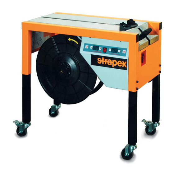
SMA 20
Art. Nr. 351.400.001
Halbautomatische Maschine zum Umreifen mit Kunststoffband
Semi-automatic machine for plastic strapping
Machine semi-automatique pour le cerclage par bande plastique
BETRIEBSANLEITUNG
OPERATING INSTRUCTIONS
MODE D'EMPLOI
02.11
Originalbetriebsanleitung
Translation of original manual
Traduction du mode d'emploi original
Ab Serie-Nr. 41'986
From serie no 41'986
A partir du no de série 41'986
DEUTSCH
ENGLISH
FRANÇAIS
3
19
35
Publicité
Chapitres
Table des Matières

Manuels Connexes pour strapex SMA 20

Sommaire des Matières pour strapex SMA 20
- Page 1 Avant l’utilisation de la machine, consultez soigneusement le mode d’emploi. SMA 20 Art. Nr. 351.400.001 Halbautomatische Maschine zum Umreifen mit Kunststoffband Ab Serie-Nr. 41‘986 Semi-automatic machine for plastic strapping From serie no 41‘986 Machine semi-automatique pour le cerclage par bande plastique A partir du no de série 41‘986...
-
Page 2: Konformitätserklärung
Telefon +47 7382 06 00 Wir erklären in alleiniger Verantwortung, dass die sales@iwdstrapping.com.au reception.as@kihlberg.no Maschine SMA 20, auf die sich diese Erklärung bezieht, mit den geltenden Bestimmungen der Belgien Österreich Richtlinie des Rates vom 17. Mai 2006 (2006/42/ Strapex Sprl Strapex GmbH EG)„Maschinen-Richtlinie“... -
Page 3: Table Des Matières
Strapex SMA 20 INHALTSVERZEICHNIS TECHNISCHE DATEN Gewicht 68 kg 1. Technische Daten 2. Allgemeines Tragkraft 150 kg 3. Betriebsarten 4. Sicherheitsvorschriften Minimale Paketgrösse Breite 45 mm 5. Beschreibung Höhe 20 mm 5.1 Aufbau 5.2 Funktionsbeschreibung Bandspannung 5–450 N stufenlos einstellbar 5.2.1 Ablaufbeschreibung... -
Page 4: Allgemeines
Strapex SMA 20 ALLGEMEINES Diese Betriebsanleitung soll das Kennenlernen der Maschine und den bestimmungsgemässen Einsatz VORSICHT! erleichtern. Die Betriebsanleitung enthält wichtige Hinweise, wie die Maschine sicher, sachgerecht Wird verwendet bei Ge- und wirtschaftlich einzusetzen ist. Das Einhalten der fahren für Leben Hinweise hilft Gefahren vermeiden, Reparaturen und und Gesundheit. -
Page 5: Sicherheitsvorschriften
Achtung: Hebezeug verwenden! Bei Packgütern > 25 kg Bestimmungsgemässe Verwendung passendes Hebezeug Mit der Maschine SMA 20 werden Pakete, Sammel- verwenden. sendungen oder empfi ndliche Waren umreift. Die Maschine ist für das Umreifen mit Verpackungs- Kunststoffbändern (Polypropylen) bestimmt. Möglicher Missbrauch Das Umreifen mit Stahlband ist mit diese Maschine nicht möglich. -
Page 6: Beschreibung
Strapex SMA 20 BESCHREIBUNG 5.1 AUFBAU Die Maschine besteht aus folgenden Hauptbaugrup- pen (siehe Fig. 2): a Antrieb b Spannheinheit c Verschliesseinheit d Maschinengestell e Elektroteil 5.2 FUNKTIONSBESCHREIBUNG a) Antrieb Der Antrieb besteht aus einem Elektro-Motor, der über einen Antriebsriemen das Schneckengetriebe sowie den Spannriemen antreibt. -
Page 7: Ablaufbeschreibung
Strapex SMA 20 Nachdem der linke Klemmer die Klemmposition er- 5.2.1 ABLAUFBESCHREIBUNG reicht hat, wird über eine Kurvenscheibe das erhitzte Heizelement zwischen die Bänder eingeschwenkt. Die Ablaufbeschreibung bezieht sich auf eine auto- Dabei erhitzen sich die Bänder. Danach wird über matische Umreifung. -
Page 8: Bedienung
Strapex SMA 20 BEDIENUNG Fig. 3 Bedienungstableau 1 Hauptschalter 5 Bandspannung stärker (Drucktaste) 2 Reset, Aggregat geht in Grundstellung zurück und 6 Maschine Ein/Aus (Kippschalter) schneidet das Band ab (Drucktaste) 7 Bandlänge kürzer (Drucktaste) 3 Bandspannung schwächer (Drucktaste) 8 Bandlänge (Digitalanzeige) 4 Bandspannung (Digitalanzeige) 9 Bandlänge länger (Drucktaste) -
Page 9: Umreifung Starten
Strapex SMA 20 6.3 UMREIFUNG STARTEN Voraussetzungen – Maschine ist an das Versorgungsnetz angeschlos- sen. Anschluss-Spannung gemäss Typenschild. – Beide arretierbaren Laufräder blockiert. – Bandspule ist eingelegt und Band vorgeschoben (siehe Kapitel 6.5). – Hauptschalter auf Stellung „1“ drehen. – Kippschalter (3/6) einschalten. -
Page 10: Bandspule Wechseln
Strapex SMA 20 6.5 BANDSPULE WECHSELN Siehe auch Schema zum Einlegen des Bandes an der Innenseite des Maschinen- gestells. – Tischblech (6/1) öffnen. Bei offenem Tischblech ist der Motor-Stromkreis unterbrochen. Heisses Heizelement nicht berühren! – Griffmutter (6/2) im Uhrzeigersinn entfernen (Links- gewinde). -
Page 11: Grundeinstellung Der Bandspannung
Strapex SMA 20 6.6 GRUNDEINSTELLUNG DER BANDSPANNUNG Ist die Bandspannung im unteren Bereich (00) zu tief oder im oberen Bereich (20) zu hoch, kann der ganze Grund-Spannbereich nach oben oder unten verschoben werden (Offset). – Seitlicher Hauptschalter auf Stellung „1“ drehen. -
Page 12: Maschinenhöhe Einstellen
Strapex SMA 20 6.8 MASCHINENHÖHE EINSTELLEN Die Tischhöhe ist einstellbar von 700 bis 830 mm. – Maschine anheben und an einem Bein (10/2) zwei Zylinderschrauben (10/1) lösen. – Bein auf die gewünschte Höhe einstellen und Zylin- derschrauben wieder festziehen. Niemals zwei Beine gleichzeitig lösen (Kippgefahr)! –... -
Page 13: Klemmer, Bandtrennung Und
Strapex SMA 20 7.2 KLEMMER, BANDTRENNUNG UND SCHIEBERPLATTE REINIGEN Ausbau – Hauptschalter auf Stellung „1“ drehen. – Kippschalter (3/6) einschalten und Drucktaste „Reset „ (3/2) betätigen. – Maschine ausschalten. – Tischblech öffnen. Heisses Heizelement nicht berühren! – Drehfeder (11/7) mit dem Daumen nach unten drücken. -
Page 14: Instandsetzung
Strapex SMA 20 INSTANDSETZUNG Für alle Instandsetzungsarbeiten Maschine von Versorgungsnetz trennen. 8.1 SCHWEISSTEMPERATUR EINSTELLEN Die Schweisstemperatur kann je nach Band dicke und Bandqualität eingestellt werden: – Für schmale, dünne Bänder = tiefe Temperatur. – Für breite, dicke Bänder = hohe Temperatur. -
Page 15: Abstand Zwischen Spannriemen Und
Strapex SMA 20 8.3 ABSTAND ZWISCHEN SPANNRIEMEN UND BANDKANAL EINSTELLEN – Tischblech öffnen. – Gleitklappe zurückschwenken. – Zylinderschraube (14/1) lösen. – Zylinderschraube (14/4) lösen und Bandkanal (14/3) so einstellen, dass der Abstand zwischen Bandkanal und Spannriemen 0,2 mm beträgt. – Zylinderschraube (14/4) anziehen. -
Page 16: Spannriemen Ersetzen
Strapex SMA 20 8.5 SPANNRIEMEN ERSETZEN Ausbau – Tischblech öffnen. – Gleitklappe (16/3) zurückschwenken. – Drehfeder (16/4) auf der Gegenseite der Spann- rolle aushängen. – Eine Zylinderschraube lösen und Bandkanal (16/1) entfernen. – Spannriemen (16/2) entfernen (durch gleichzeitiges Drehen des Zahnrades) und ersetzen. -
Page 17: Klemmer (Abschneidmesser) Ersetzen
Strapex SMA 20 8.7 KLEMMER (ABSCHNEIDMESSER) ERSETZEN Ausbau – Hauptschalter auf Stellung „1“ drehen. – Kippschalter (3/5) einschalten und Drucktaste „Reset „ (3/1) betätigen. – Tischblech öffnen. Heisses Heizelement nicht berühren! – Drehfeder mit dem Daumen nach unten drücken und Schieberplatte (18/3) nach hinten aus Ver- schliesseinheit ausfahren. -
Page 18: Beheben Von Störungen
Strapex SMA 20 F1 = Primär 8.8 BEHEBEN VON STÖRUNGEN F2 = Motor F3 = Heizelement Schweisstrafo Voraussetzungen F4 = Steuertrafo 24 V – Maschine korrekt am Versorgungsnetz angeschlos- sen. Störungen dürfen nur von ausgebildetem – Feinsicherungen im Elektroteil ist nicht defekt. -
Page 19: Fig. 1
Strapex SMA 20 TECHNICAL DATA TABLE OF CONTENTS Weight 68 kg (150 lbs) 1. Technical data 2. General information Carrying weight 150 kg (330 lbs) 3. Modes of operation 4. Safety instructions Minimum dimension Width 45 mm (1 “) 5. Description... -
Page 20: Declaration Of Conformity
DECLARATION OF CONFORMITY We take sole responsibility for declaring that the EN ISO 13857, EN ISO 13850, EN 61000-6-2, machine SMA 20, to which this declaration refers, EN 61000-6-3, EN 50371, EN 415-8 EEC-Design certifi cation: 1053 is in full compliance with the current requirements of the guidelines laid down by the council on 17th Place of certifi... -
Page 21: Safety Instructions
Strapex SMA 20 SAFETY INSTRUCTIONS Warning: Inform yourself! Do not touch! Read the operating instructions Heat sealing plate heats up to carefully. jklsfjklsdjš lksdfjkl jkljsdllkjjkljsd 325°C. Preventive and corrective main- fkljjklkjkljsdafj asdfjklkjjkljklj ksldafkjkljklš jkljklkljsdafjlkj jkljjkljklkljljlk tenance on the machine may... -
Page 22: Description
Strapex SMA 20 DESCRIPTION 5.1 DESIGN The machine consists of the following main assem- blies (see Fig. 2): a Drive unit b Tensioning unit c Sealing unit d Machine frame e Electric part 5.2 FUNCTIONAL DESCRIPTION a) Drive unit The drive unit consists of an electric motor which actu- ates the worm drive and the tensioning belt by means of a drive belt. -
Page 23: Description Of Operating Sequence
Strapex SMA 20 After the left clamp has reached the clamping position, 5.2.1 DESCRIPTION OF OPERATING SEQUENCE the hot heating element is swivelled in between the straps by means of a cam. In this way the straps are The operational sequence relates to automatic strap- heated. -
Page 24: Operating Instructions
Strapex SMA 20 OPERATION Fig. 3 Control panel 1 Main switch 6 Machine on/off (toggle switch) 2 Reset, aggregate returns to starting position and 7 Strap length shorter (tip-activated button) cuts the strap (push-button) 8 Strap length (digital display) 3 Strap tension weaker (push-button) -
Page 25: Start Strapping
Strapex SMA 20 6.3 START STRAPPING Prerequisites – Machine is connected to the mains supply. Power supply according to identifi cation plate. – Both locking wheels locked. – Strap coil has been installed and strap feed is performed (see Chapter 6.5). -
Page 26: Change Strap Coil
Strapex SMA 20 6.5 CHANGE STRAP COIL See also diagram for threading the strap into the inside of the machine frame. – Open table top (6/1). When the table top is open the power circuit of the motor is interrupted. -
Page 27: Basic Setting Of The Strap Tension
Strapex SMA 20 6.6 BASIC SETTING OF THE STRAP TENSION If the strap tension is too low at the bottom of the range (00) or too high at the top of the range (20), then the entire basic tension range can be displaced upwards or downwards (offset). -
Page 28: Adjust Machine Height
Strapex SMA 20 6.8 ADJUST MACHINE HEIGHT The table height is adjustable from 700 to 830 mm. – Hold machine and loosen two cylinder screws (10/1) on one of the legs (10/2). – Adjust leg to required height and tighten up cylinder screws again. -
Page 29: Clean Clamps, Strap Separator And Slide Plate
Strapex SMA 20 7.2 CLEAN CLAMPS, STRAP SEPARATOR AND SLIDE PLATE Remove – Turn Main switch to position „1“. – Toggle switch (3/6) on and activate push-button „Reset“ (3/1). – Switch off machine. – Open table top. Do not touch heating element! –... -
Page 30: Corrective Maintenance
Strapex SMA 20 CORRECTIVE MAINTENANCE Disconnect the machine from the mains supply before undertaking any maintenance work. 8.1 ADJUST WELDING TEMPERATURE The welding temperature can be adjusted to suit the strap thickness and strap quality: – For narrow, thin straps = low temperature. -
Page 31: Adjust Gap Between Tension Belt And Strap Channel
Strapex SMA 20 8.3 ADJUST GAP BETWEEN TENSION BELT AND STRAP CHANNEL – Open table top. – Swivel back slide plate. – Undo cylinder screw (14/1). – Undo cylinder screw (14/4) and adjust strap chan- nel (14/3) so that the gap between strap channel and tensioning belt is 0.2 mm. -
Page 32: Replace Tension Belt
Strapex SMA 20 8.5 REPLACE TENSION BELT Remove – Toggle switch (3/6) on. – Activate push-button „Reset“ (3/2). – Open table top. – Swivel back slide fl ap (16/3). – Hook out torsion spring (16/4) on the opposite side of the tension roller. -
Page 33: Replace Clamps (Knife)
Strapex SMA 20 8.7 REPLACE CLAMPS (KNIFE) Remove – Turn Main switch to position „1“. – Toggle switch (3/6) on. – Activate push-button „Reset“ (3/2). – Open table top. Do not touch hot heating element! – Press torsion spring downwards with the thumb and drive slide plate (18/3) backwards out of the sealing unit. -
Page 34: Elimination Of Faults
Strapex SMA 20 F1 = Primary 8.8 ELIMINATION OF FAULTS F2 = Motor F3 = Heating element welding transformer Preconditions F4 = Control transformator 24 V – Machine is correctly connected to the mains supply. – Micro fuses in the electrical section are not def- Faults can often only be eliminated by ective. -
Page 35: Polypropylene (Pp)
Strapex SMA 20 TABLE DES MATIÈRES DONNÉES TECHNIQUES Poids 68 kg 1. Données techniques 2. Instructions générales Force de traction 150 kg 3. Mode d‘exploitation 4. Instructions de sécurité Dimensiones minimales 5. Description du coils Largeur 45 mm 5.1 Montage Hauteur 20 mm 5.2 Description du fonctionnement... -
Page 36: Instructions Générales
DÉCLARATION DE CONFORMITÉ Nous déclarons sous notre propre responsabilité EN ISO 13857, EN ISO 13850, EN 61000-6-2, que machine SMA 20 ci-dessus, au sujet duquel EN 61000-6-3, EN 50371, EN 415-8 se réfère cette déclaration, est conforme avec les CEE-Certifi cat de modéle: 1053 prescriptions en vigueur de la directive du conseil Bureau de certifi... -
Page 37: Instructions De Sécurité
Ne mettez pas la main ou d‘autres parties du corps Utilisation conforme entre La machine SMA 20 cercle les colis, les envois grou- la bande et l‘emballage. pés ou les marchandises délicates. Attention: La machine est destiné au cerclage des emballages Utiliser un engin de avec des bandes en plastique (polypropylène). -
Page 38: Description
Strapex SMA 20 DESCRIPTION 5.1 MONTAGE La machine se compose des modules principaux suivants voir fi g. 2. a Entraînement b Unité de tension c Unité de sertissage d Bâti de la machine e Partie eléctrique 5.2 DESCRIPTION DU FONCTIONNEMENT a) Entraînement... -
Page 39: Description Du Processus
Strapex SMA 20 Après que la pince gauche a atteint la position de 5.2.1 DESCRIPTION DU PROCESSUS blocage, l‘élément de chauffage chaud est pivoté entre les bandes par une came. Ainsi les bandes se La description du processus concerne le cerclage chauffent. -
Page 40: Mise En Service
Strapex SMA 20 MISE EN SERVICE Fig. 3 Tableau de service 1 Commutateur 6 Machine marche/arrêt (interrupteur basculant) 2 Réinitialisation, l‘agrégat recule à sa position de 7 Diminution de la longueur (bouton de calibrage) base et coupe la bande (bouton-poussoir) 8 Longueur de la bande (affi... -
Page 41: Début Du Cerclage
Strapex SMA 20 6.3 DÉBUT DU CERCLAGE Conditions initiales – La machine est reliée au réseau d‘alimentation. Tension de raccordement selon la plaque signalé- tique. – Les deux roues verrouillables bloquées. – La bobine de bande est chargée, et la bande enfi lée (voir chapitre 6.5). -
Page 42: Chargement De La Bobine De Bande
Strapex SMA 20 6.5 CHARGEMENT DE LA BOBINA DE BANDE Voir également le schéma pour enfi ler la bande sur le côté intérieur du bâti de la machine. – Ouvrir la table (6/1). Lorsque la table est ouverte, le circuit de courant du moteur est interrompu. -
Page 43: Réglage De Base De La Tension De La Bande
Strapex SMA 20 6.6 RÉGLAGE DE BASE DE LA TENSION DE LA BANDE Si le réglage de la bande est trop bas dans la gamme de tension inférieure (00) ou trop haute dans la gamme supérieure (20), la gamme entière du réglage de base peut être décalée vers le haut ou vers le bas (Offset). -
Page 44: Réglage De La Hauteur De La Machine
Strapex SMA 20 6.8 RÉGLAGE DE LA HAUTEUR DE LA MACHINE La hauteur de la machine est réglable de 700 à 830 mm. – Desserrer les deux vis cylindriques (10/1) d‘un montant (10/2). – Régler le montant à la hauteur souhaitée et resser- rer les vis cylindriques. -
Page 45: Nettoyage Des Pinces, Du Séparateur De Bande Et De La Plaque Du Curseur
Strapex SMA 20 7.2 NETTOYAGE DES PINCES, DU SÉPARATEUR DE BANDE ET DE LA PLAQUE DU CURSEUR Démontage – Commutateur en position „1“. – Enclencher l‘interrupteur basculat (3/6) et actionner le bouton-poussoir „Réinitialisation“ (3/2). – Déclencher la machine. – Ouvrir la table. -
Page 46: Réparations Et Réglages
Strapex SMA 20 RÉPARATIONS ET RÉGLAGES Avant de commencer les travaux de réparations et de réglages, toujours retirer la fi che du réseau. 8.1 RÉGLAGE DE LA TEMPERATURE DE SOUDURE La température de soudure est réglée d‘après l‘épaisseur et la qualité de la bande: –... -
Page 47: Réglage De La Distance Entre La Courroie De Tension Et Le Canal De La Bande
Strapex SMA 20 8.3 RÉGLAGE DE LA DISTANCE ENTRE LA CO- ROIE DE TENSION ET LE CANAL DE BANDE – Ouvrir la table. – Basculer en arrière le clapet. – Dévisser la vis cylindrique (14/1). – Dévisser la vis cylindrique (14/4) et régler le canal de la bande (14/3) de telle sorte que sa distance avec la courroie de tension soit de 0,2 mm. -
Page 48: Remplacement De La Courroie De Tension
Strapex SMA 20 8.5 REMPLACEMENT DE LA COURROIE DE TENSION Démontage – Enclencher l‘interrupteur bascalant (3/6). – Actionner le bouton-poussoir „Réinitialisation“ (3/2). – Ouvrir la table. – Basculer le clapet (16/3) en arrière. – Décrocher le ressort de torsion (16/4) sur l‘autre côté... -
Page 49: Remplacement De La Pince (Couteau)
Strapex SMA 20 8.7 REMPLACEMENT DE LA PINCE (COUTEAU) Démontage – Commutateur en position „1“. – Enclencher l‘interrupteur basculat (3/6). – Actionner le bouton-poussoir „Réinitialisation“ (3/2). – Ouvrir la table. Ne pas toucher l‘élément de chauffage brûlant! – Avec le pouce, appuyer sur le ressort de torsion contre le bas et retirer par l‘arrière la plaque du... -
Page 50: Dépannage
Strapex SMA 20 F1 = Primaire 8.8 DÉPANNAGE F2 = Moteur F3 = Elément de chauffage transformateur Conditions initiales F4 = Transformateur de commande 24 V – La machine est correctement connectée au réseau d‘alimentation. Les pannes ne doivent être réparées que par –...