CREE LIGHTING Noctura Série Instructions D'installation
Masquer les pouces
Voir aussi pour Noctura Série:
- Instructions d'installation (9 pages) ,
- Instructions d'installation (2 pages) ,
- Instructions d'installation (2 pages)
Publicité
Les langues disponibles
Les langues disponibles
Liens rapides
When using electrical equipment, basic safety precautions should always be followed including the following:
READ AND FOLLOW ALL SAFETY INSTRUCTIONS
1.
DANGER- Risk of shock- Disconnect power before installation.
DANGER – Risque de choc – Couper l'alimentation avant l'installation.
2.
This luminaire must be installed in accordance with the NEC or your local electrical code. If you are not familiar with these codes
and requirements, consult a qualified electrician.
Ce produit doit être installé conformément à NEC ou votre code électrique local. Si vous n'êtes pas familier avec ces codes et ces
exigences, veuillez contacter un électricien qualifié.
3.
Suitable for wet locations.
Convient aux emplacements mouilles
4.
Suitable for operation in ambient not exceeding 40°C.
Peut etre utilise a une temperature ambiante n'excedant pas 40°C.
5.
Suitable for mounting within 1.2M (4ft) of the ground.
Peut etre installe a moins de 1,2 m (4 pi) du sol.
6.
Min. 75°C supply conductors.
Les fils d'alimentation 75°c min.
7.
Class 1 wiring only.
Cablage de classe 1 uniquement.
SAVE THESE INSTRUCTIONS FOR FUTURE REFERENCE
TO INSTALL:
1
Male End of
Connector
Female End of
Connector
TRUNNION MOUNT- REQUIRES USE OF NTX-TR ACCESSORY
STEP 1:
Plug the female end of the quick connect,
supplied with the trunnion, into the male
connector on the luminaire. Make sure the two
halves lock together. See Figure 1.
STEP 2:
Align the four holes in the inner trunnion with
the four tapped holes in the luminaire housing.
Attach the trunnion to the luminaire using
the (4) 5/16" (8 mm) bolts and lockwashers
supplied with the trunnion kit. Tighten bolts to
132 in-lbs (15 N·m). See Figure 2.
STEP 3:
Mount the luminaire in the desired location
1 of 5
IMPORTANT SAFEGUARDS
2
(4) 5/16" (8 mm)
Bolts
Inner
Trunnion
#10-24 Screws
to Adjust the
(2) 5/16"
Orientation
(8 mm)
Bolts
using (2) 3/8" (10 mm) bolts (customer
supplied) appropriate for the mounting surface.
See Figure 3.
STEP 4:
Make wiring connections to the cord leads per
the Electrical Connections section.
STEP 5:
Remove #10-24 positioning screws on both
sides of the trunnion.
STEP 6:
Loosen 5/16" (8 mm) hex head bolts located on
both sides of the
trunnion.
STEP 7:
INSTRUCTIONS D'INSTALLATION
3
Outer Trunnion.
Fix this on the
Mounting Surface
For Wall
Mounting,
Keep the
Keyholes Facing
Upwards During
Installation
Rotate trunnion to desired tilt angle. Line up
inner and outer trunnion positioning holes.
STEP 8:
Insert one #10-24 screw, removed in Step
5, into matching holes of inner and outer
trunnions. Tighten screw to 30 in-lbs (35 N·m).
Repeat with screw on opposite side of trunnion.
STEP 9:
Tighten both 5/16" hex head bolts on opposite
sides of the
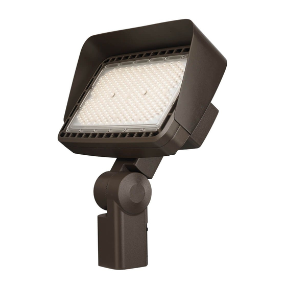
Noctura Series
LED Flood Light
Large Flood Light
INSTALLATION INSTRUCTIONS
Bolts into Keyholes Slots First
trunnion
to 132 in-lbs (15 N·m).
LPN00630X0002A0_B
Publicité

Manuels Connexes pour CREE LIGHTING Noctura Série

Sommaire des Matières pour CREE LIGHTING Noctura Série
- Page 1 Noctura Series LED Flood Light Large Flood Light INSTALLATION INSTRUCTIONS IMPORTANT SAFEGUARDS INSTRUCTIONS D’INSTALLATION When using electrical equipment, basic safety precautions should always be followed including the following: READ AND FOLLOW ALL SAFETY INSTRUCTIONS DANGER- Risk of shock- Disconnect power before installation. DANGER –...
-
Page 2: Important
Front Half of Mounting Mounting Arm Fix this Arm. Fix this to the to the Luminaire Head Luminaire Head using (4) Bolts Twist Lock Rear Trunnion Mounting Bracket Photocell Bracket. Fix this of the Trunnion Receptacle to the Mounting Wiring Surface Compartment Cover... - Page 3 Upper Arm to be Button Photocell Fixed on to the (Ordered Separately) Luminaire Head Allowable using (4) bolts Photocell Tilt Lower Half of the Angle Rang Arm to be Fixed on the Mounting Pole 45° -45° From From Vertical Vertical Wiring Compartment Cover Plate...
- Page 4 STEP 8: If 3/8” bolt holding the two halves of the adjustable arm together Upper Arm to be Fixed on to the was not loosened in Step 5, loosen the bolt (DO NOT remove it) at Luminaire Head this time. using (4) bolts Lower Half of the STEP 9:...
-
Page 5: Electrical Connections
NOTE: For dimming connections, use Class 1 wiring methods only. © 2019 Cree Lighting, A company of IDEAL INDUSTRIES. All rights reserved. For informational purposes only. Content is subject to change. See www.creelighting.com/warranty for warranty and specifications. Cree and the Cree logo are ®... - Page 6 Série Noctura Projecteurs à DEL Grand Projecteur INSTRUCTIONS D’INSTALLATION MESURES DE SÉCURITÉ IMPORTANTES INSTALLATION INSTRUCTIONS Lorsque vous utilisez un équipement électrique, vous devez toujours respecter les règles de sécurité élémentaires, notamment les suivantes : LISEZ ET SUIVEZ TOUTES LES CONSIGNES DE SÉCURITÉ DANGER –...
- Page 7 Moitié avant du montage du bras Fixez ceci à la Montage du bras Fixez tête du luminaire ceci à la tête du luminaire avec (4) boulons Réceptacle de la Crosse arrière du Crosse de fixation photocellule à tourillon Fixez ceci à la du tourillon verrou tournant surface de montage...
- Page 8 Photocellule à bouton Partie supérieure du (commandé séparément) bras doit être fixée sur le luminaire avec Angle d'inclinaison (4) boulons toléré de la cellule Partie inférieure du photoélectrique bras à fixer sur le poteau de montage -45° 45° Par rapport à Par rapport à...
- Page 9 ÉTAPE 8 : Si le boulon de 10 mm (3/8 po) maintenant les deux moitiés Partie supérieure du bras doit être fixée du bras ajustable ensemble n'a pas été desserré à l'étape 5, sur le luminaire desserrez-le (NE PAS le retirer) à cette étape. avec (4) boulons ÉTAPE 9 : Partie inférieure du...
-
Page 10: Raccordements Électriques
1. © 2019 Cree Lighting, une société d’IDEAL INDUSTRIES. Tous droits réservés. À titre informatif seulement. Le contenu est sujet à changement. Allez sur www.creelighting.com/warranty pour obtenir des renseignements sur la garantie et les caractéristiques techniques.