Table des Matières
Publicité
Les langues disponibles
Les langues disponibles
Liens rapides
Publicité
Table des Matières

Manuels Connexes pour Dal Zotto INSERTO 700 ELITE CRYSTAL


Sommaire des Matières pour Dal Zotto INSERTO 700 ELITE CRYSTAL
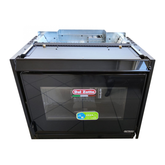
- Page 1 MANUALE UTENTE STUFE A PELLET PELLET STOVES USER MANUAL MANUEL UTILISATEUR POÊLES À PELLET BENUTZERHANDBUCH PELLETÖFEN MANUAL DEL USUARIO ESTUFAS DE PELLET INSERTO 700 ELITE CRYSTAL MADE ITALY design & production 004277115 REV.005...
- Page 2 ApplicAre etichettA dAti technici...
-
Page 3: Table Des Matières
ORDINARIA MANUTENZIONE ..................................10 INSTALLAZIONE ......................................11 DISTANZE MINIME ..............................................11 PREDISPOSIZIONI PER MANUTENZIONE ......................................11 INSTALLAZIONE INSERTO 700 ELITE CRYSTAL ............................13 MONTAGGIO CON BASAMENTO SCORREVOLE ...................................13 INSERTO 700 ELITE CRYSTAL ..........................................13 MONTAGGIO CON PIEDISTALLO OPZIONALE ............................14 KIT CARICAMENTO FRONTALE PELLET OPZIONALE ..........................14 CONDOTTI DI RICIRCOLO ARIA .................................. - Page 4 ROUTINE MAINTENANCE ....................................40 INSTALLATION ........................................ 41 MINIMUM DISTANCES ............................................41 PREPARATIONS FOR MAINTENANCE ........................................41 INSTALLING INSERTO 700 ELITE CRYSTAL ..............................43 ASSEMBLY WITH SLIDING BASE ..........................................43 INSERTO 700 ELITE CRYSTAL ..........................................43 PEDESTAL ASSEMBLY OPTIONAL : ................................44 FRONT PELLET FEEDING KIT OPTIONAL ..............................44 AIR CIRCULATION PIPES ....................................
- Page 5 ENTRETIEN ORDINAIRE ....................................70 INSTALLATION ........................................ 71 DISTANCES MINIMALES ............................................71 CONSIGNES POUR L’ENTRETIEN .........................................71 INSTALLATION INSERTO 700 ELITE CRYSTAL ............................. 73 MONTAGE AVEC BÂTI COULISSANT ........................................73 INSERTO 700 ELITE CRYSTAL ..........................................73 MONTAGE AVEC SOCLE EN OPTION : ................................ 74 KIT DE CHARGEMENT FRONTAL DES PELLETS EN OPTION ........................74 CONDUITS DE RECIRCULATION DE L'AIR ..............................
- Page 6 FACHGERECHTE WARTUNG ..................................100 INSTALLATION ......................................101 MINDESTABSTÄNDE ............................................. 101 VORBEREITUNGEN FÜR DIE WARTUNG ......................................101 INSTALLATION INSERTO 700 ELITE CRYSTAL ............................103 MONTAGE MIT SCHIEBEGESTELL ........................................103 INSERTO 700 ELITE CRYSTAL ..........................................103 MONTAGE MIT UNTERGESTELL OPTIONAL ............................104 BAUSATZ ZUR FRONTALEN PELLETZUFUHR OPTIONAL ........................
- Page 7 MANTENIMIENTO ORDINARIO ................................... 130 INSTALACIÓN ....................................... 131 DISTANCIAS MÍNIMAS ............................................131 PREDISPOSICIONES PARA MANTENIMIENTO .................................... 131 INSTALACIÓN INSERTO 700 ELITE CRYSTAL ............................133 MONTAJE CON BASE DESLIZANTE ......................................... 133 INSERTO 700 ELITE CRYSTAL ..........................................133 MONTAJE CON PEDESTAL OPCIONAL ..............................134 KIT DE CARGA FRONTAL DE PELLET OPCIONAL ............................
-
Page 8: Italiano
Vi ringraziamo per aver scelto la nostra azienda; il nostro prodotto è un’ottima soluzione di riscaldamento nata dalla tecnologia più avanzata con una qualità di lavorazione di altissimo livello ed un design sempre attuale, al ne di farVi godere sempre in assoluta sicurezza la fantastica sensazione che il calore della amma può... - Page 9 NON GIOCHINO CON L’APPARECCHIO. Š LA PULIZIA E LA MANUTENZIONE DESTINATA AD ESSERE EFFETTUATA DALL'UTILIZZATORE NON DEVE ESSERE EFFETTUATA DA BAMBINI SENZA SORVEGLIANZA. Š NON TOCCARE IL GENERATORE SE SI È A PIEDI NUDI E CON PARTI DEL CORPO BAGNATE O UMIDE. Š...
-
Page 10: Ordinaria Manutenzione
ASSISTENZA TECNICA E, IN OGNI CASO, NON DISABILITARE I SISTEMI DI SICUREZZA. Š IN CASO DI INCENDIO DELLA CANNA FUMARIA MUNIRSI DI ADEGUATI SISTEMI PER SOFFOCARE LE FIAMME O RICHIEDERE L’INTERVENTO DEI VIGILI DEL FUOCO. Š QUESTO APPARECCHIO NON DEVE ESSERE UTILIZZATO COME INCENERITORE DI RIFIUTI Š... -
Page 11: Installazione
INSTALLAZIONE GENERALITÀ Gli allacciamenti scarico fumi e idraulico devono essere eseguiti da personale quali cato che deve rilasciare documentazione di conformità di installazione secondo le norme nazionali. L'installatore deve consegnare al proprietario o a chi per esso, ai sensi della legislazione vigente, la dichiarazione di conformità dell'impianto, correlata di: 1) il libretto d' uso e manutenzione dell' apparecchio e dei componenti dell'impianto (come per esempio canali da fumo, camino, ecc.);... -
Page 12: Scarico Fumi
In qualsiasi condizione, compresa la presenza di cappe aspiranti e/o impianti di ventilazione forzata controllata, la di erenza di pressione tra i locali di installazione del generatore e l’esterno deve risultare un valore sempre uguale o minore di 4 Pa. In presenza di apparecchi a gas di tipo B a funzionamento intermittente non destinati al riscaldamento deve essere ad essi dedicata un'apertura di aerazione e/o ventilazione. -
Page 13: Installazione Inserto 700 Elite Crystal
INSTALLAZIONE INSERTO 700 ELITE CRYSTAL L’inserto viene fornito di un basamento scorrevole in ferro che permette di installarlo in un camino preesistente. Questo basamento scorrevole permette di estrarre in modo agevolato l’inserto sia per il caricamento del pellet all’interno del serbatoio sia per eventuali manutenzioni o pulizie di ne stagione. -
Page 14: Montaggio Con Piedistallo Opzionale
MONTAGGIO CON PIEDISTALLO OPZIONALE Posizionare il basamento nel punto desiderato e tramite i piedini regolare l’altezza desiderata (i bulloni sono posti nei quattro lati esterni del piedistallo in basso). Prevedere una presa di corrente nel retro del piedistallo in modo tale che la spina sia accessibile una volta eseguita l’installazione. - Page 15 Le misure da rispettare sono le seguenti: Š PARTE INFERIORE ENTRATA ARIA FREDDA A SUPERFICIE MINIMA COMPLESSIVA 550 CM². Š PARTE SUPERIORE USCITA ARIA CALDA A SUPERFICIE MINIMA COMPLESSIVA 550 CM². QUESTO SISTEMA DI AERAZIONE È TOTALMENTE INDIPENDENTE DALLA PRESA D’ARIA PER LA COMBUSTIONE!! IMPORTANTE: TUTTE LE APERTURE EFFETTUATE PER CREARE UN CORRETTO RICIRCOLO D’ARIA, DOVRANNO ESSERE RESE INACCESSIBILI TRAMITE OPPORTUNE GRIGLIE O RETI DI PROTEZIONE, GARANTENDO COMUNQUE IL MINIMO PASSAGGIO D’ARIA RICHIESTO.
-
Page 16: Estrazione Inserto
Basamento Inserto Presa d'aria Presa d'aria 275cm² 275cm² SICURA DEL INSERTO BLOCCAGGIO E SBOCCAGGIO Aprire la porta fuoco e ruotare tramite l'attizzatoio in dotazione il chiavistello posto nell’angolo in basso a sinistra in senso orario. Per capire se l’inserto è correttamente agganciato al basamento, collegare la spina alla presa di corrente e veri care il funzionamento tramite il telecomando in dotazione. -
Page 17: Montaggio Cornici
MONTAGGIO CORNICI Š Cornice frontale Š Cornici laterali N.B. Eventuali travi in legno situate al di sopra dell’inserto vanno protette con materiale ignifugo. Il montaggio della cornice è importante in quanto permette un corretto ricircolo d’aria nell’inserto e di conseguenza un ottimo funzionamento del prodotto. -
Page 18: Deflettore Basculante Frontale
DEFLETTORE BASCULANTE FRONTALE L'inserto è dotato di un de ettore frontale che deve essere aperto prima di avviare l'inserto. Se si tenta una accensione con il de ettore chiuso, il display visualizzerà sul il display "GRIGLIA CHIUSA - ATTENZIONE". APERTURA DEFLETTORE Sollevare il de ettore tramite l'apposita linguetta presente sul lato destro no al bloccaggio in apertura. -
Page 19: Quadro Comandi
QUADRO COMANDI PULSANTE ON/OFF REGOLAZIONE POTENZA VISUALIZZAZIONE DEI VARI IMPOSTAZIONE PER ACCEDERE DI FUNZIONAMENTO MESSAGGI DI TESTO TEMPERATURA AL MENÙ’ Bianco - Acceso Bianco lampeggiante - Riserva serbatoio pellet Rosso - Spento Verde - STBY Rosso lampeggiante - In allarme LEGENDA ICONE DISPLAY Indica la ricezione del segnale radio Indica la funzione di programmazione settimanale... -
Page 20: Menù Generale
MENÙ GENERALE RITORNA INDIETRO ESCI SCORRIMENTO PARAMETRI: SUCCESSIVO 2 ; PRECEDENTE 3 22.5°C 14:10 MODIFICA DATI IMPOSTAZIONE: AUMENTO 4 ; DIMINUZIONE 5 CONFERMA ACCESSO AL MENÙ SET OROLOGIO ABILITA CRONO GIORNO ABILITA CRONO PROG. 1 - 2 - 3 - 4 ON/OFF SET CRONO START PRG1... -
Page 21: Il Telecomando
IL TELECOMANDO Mediante il telecomando sì ha la possibilità di regolare tutto ciò che normalmente è possibile eseguire con il display Lcd. Nella tabella sottostante in dettaglio le varie funzioni: Premendo il tasto per tre secondi la stufa andrà in accensione o in ON / OFF spegnimento INCREMENTO POTENZA... -
Page 22: Frequenza Di Rete 50/ 60Hz
FREQUENZA DI RETE 50/ 60HZ Nel caso in cui la stufa sia installata in un paese con una frequenza di 60Hz, la stufa in visualizzerà "frequenza rete errata ". Variare la frequenza come descritto in seguito. PROCEDURA COMANDI Premere il tasto 6, Š... -
Page 23: Funzionamento E Logica
FUNZIONAMENTO E LOGICA 22.5°C 14:10 ACCENSIONE Una volta veri cati i punti in precedenza elencati, premere il tasto 1 per tre secondi per accendere la stufa. Per la fase di accensione sono a disposizione 15 minuti, dopo l'avvenuta accensione e raggiungimento della temperatura di controllo, la stufa interrompe la fase di accensione e passa in AVVIAMENTO. -
Page 24: Termostato Supplementare Opzionale
TERMOSTATO SUPPLEMENTARE OPZIONALE L’apparecchio ha la possibilità di controllare la temperatura ambiente tramite un termostato supplementare (opzione). Dopo l’accensione (premendo il tasto 1 o tramite modalità crono) la stufa lavorerà per raggiungere il set impostato nel termostato visualizzando (contatto chiuso). La sonda ambiente di serie, viene automaticamente ignorata. LAVORO A temperatura raggiunta dal termostato (contatto aperto) la stufa si porterà... -
Page 25: V1 Aria
CARENZA DI COMBUSTIBILE: Š la stufa non riesce mai a sviluppare una amma adeguata tendendo a rimanere sempre molto bassa anche a potenza elevata. Š alla minima potenza la stufa tende quasi a spegnersi portando la stufa in allarme “ ”. -
Page 26: Tasti Bloccati
Nel caso in cui la funzione Stby non sia attivata (OFF ), se la stufa raggiunge la temperatura ambiente impostata si porterà al minimo, modulando e visualizzando modula. Quando la temperatura ambiente sarà inferiore il set impostato la stufa ricomincerà a lavorare alla potenza impostata sul display visualizzando lavoro. -
Page 27: V2 Aria
V2 ARIA Il menù permette di regolare in percentuale la velocità della ventilazione canalizzata. PROCEDURA COMANDI Premere il tasto 6, apparirà la scritta SET OROLOGIO. Š Premere più volte il tasto 2 no alla visualizzazione UTENTE Š Premere il tasto 6. Š... -
Page 28: Esempio Di Programmazione
ESEMPIO DI PROGRAMMAZIONE Supponiamo ora di voler utilizzare la funzione Programmatore settimanale e di voler utilizzare 4 fasce orarie nel seguente modo: - Fascia oraria 1: dalle 08:00 alle 12:00 per tutti i giorni della settimana, con temperatura ambiente a 19°C, esclusi sabato e domenica - Fascia oraria 2: dalle 15:00 alle 22:00 solo il sabato e la domenica, con temperatura ambiente 21°C SPEGNIMENTO 1^ FASCIA PROCEDURA COMANDI:... -
Page 29: Pulizia E Manutenzione
PULIZIA E MANUTENZIONE ESEGUIRE LE INDICAZIONI SEMPRE NELLA MASSIMA SICUREZZA! Š Assicurarsi che la spina del cavo di alimentazione sia staccata in quanto il generatore potrebbe essere stata programmata per accendersi. Š Che il generatore sia freddo in ogni sua parte. Š... - Page 30 Aprire la porta - Pulire il vetro con un panno umido Non spruzzare mai direttamente sul vetro ceramico il detergente o qualsiasi altro liquido per la pulizia PULIZIA BRACIERE E CAMERA DI COMBUSTIONE 1. Aspirare i residui presenti nel braciere 2.
-
Page 31: Cassetto Cenere
OGNI 3/4 GIORNI SETTIMANALE CASSETTO CENERE Veri care ogni 3-4 giorni il contenuto del cassetto cenere e svuotare il contenuto almeno una/due volte a settimana. Dove previsto, aprire /togliere lo sportello inferiore. Togliere il cassetto cenere estraibile e svuotarlo in un aposito contenitore. Aspirare la zona sottostante dove aloggia il cassetto cenere estaibile. - Page 32 ITALIANO...
-
Page 33: Manutenzione Ordinaria Eseguita Dai Tecnici Abilitati
MANUTENZIONE ORDINARIA ESEGUITA DAI TECNICI ABILITATI La manutenzione ordinaria deve essere eseguita almeno una volta all'anno. Il generatore utilizzando pellet come combustibile solido necessità di un intervento annuale di manutenzione ordinaria che deve essere e ettuate da un Tecnico abilitato, utilizzando esclusivamente ricambi originali. Il mancato rispetto può... -
Page 34: Visualizzazioni
VISUALIZZAZIONI DISPLAY MOTIVAZIONE Stufa spenta START E’ in corso la fase di start CARICO PELLET E’ in corso il carico del pellet durante la fase di accensione ACCENSIONE E’ in corso la fase di accensione AVVIO E’ in corso la fase di avvio LAVORO E’... -
Page 35: Mancata Accensione
Accesa: indica la presenza di un allarme Lampeggiante: indica la disattivazione del sensore di depressione. Indica la presenza di un allarme. L’allarme può essere resettato solo se il motore fumi si è fermato e se sono trascorsi 15 minuti dalla visualizzazione stessa dell’allarme, premendo il tasto 1 per 3 secondi. -
Page 36: Condizioni Di Garanzia
CONDIZIONI DI GARANZIA I prodotti DAL ZOTTO marchio commerciale di LA NORDICA S.p.A. sono garantiti, nell’ambito della comunità europea, per un periodo di 24 mesi dalla data di acquisto. L’acquisto deve essere provato da un documento scalmente valido rilasciato dal rivenditore (scontrino scale, fattura o bolla di trasporto) che identi chi il prodotto acquistato e la data di acquisto e/o consegna dello stesso. -
Page 37: Smaltimento
Qualora il Prodotto venisse riparato presso uno dei Centri Assistenza Tecnica Autorizzati indicati dalla DAL ZOTTO e nel caso di sostituzione del prodotto, il trasporto sarà gratuito. Nei casi in cui il tecnico fosse in grado di riparare il prodotto presso il domicilio dell’utente, è lo stesso si ri utasse, il trasporto in laboratorio e la riconsegna saranno invece a suo carico. -
Page 38: English
We thank you for having chosen our company; our product is a great heating solution developed from the most advanced technology with top quality machining and modern design, aimed at making you enjoy the fantastic sensation that the heat of a ame gives, in complete safety. WARNINGS This instructions manual is an integral part of the product: make sure that it always accompanies the appliance, even if transferred to another owner... - Page 39 CHILDREN WITH REDUCED PHYSICAL, SENSORY AND MENTAL CAPACITIES OR WHO ARE UNSKILLED PERSONS, UNLESS THEY ARE SUPERVISED AND TRAINED REGARDING USE OF THE APPLIANCE BY A PERSON RESPONSIBLE FOR THEIR SAFETY. Š THE CLEANING AND MAINTENANCE REQUIRED BY THE USER MUST NOT BE PERFORMED BY CHILDREN WITHOUT SUPERVISION.
-
Page 40: Routine Maintenance
SYSTEMS. Š IN THE EVENT THE FLUE CATCHES FIRE, USE SUITABLE SYSTEMS FOR SUFFOCATING THE FLAMES OR REQUEST HELP FROM THE FIRE BRIGADE. Š THIS APPLIANCE MUST NOT BE USED TO BURN WASTE Š DO NOT USE ANY FLAMMABLE LIQUIDS FOR IGNITION Š... -
Page 41: Installation
INSTALLATION GENERAL The ue gas exhaust and hydraulic connections must be carried out by quali ed personnel who must issue installation conformity documentation compliant with national standards. The installer must provide the owner or person acting for him, according to the legislation in force, with the declaration of conformity, supplied with: 1) the use and maintenance manual of the appliance and of the system components (such as for example, the smoke ducts, chimney, etc.);... -
Page 42: Flue Gas Exhaust
In the presence of type B gas appliances with intermittent operation not intended for heating, they must have their own aeration and/or ventilation opening. The air inlets must meet the following requirements: Š they must be protected with grids, metal mesh, etc., but without reducing the net useful section; Š... -
Page 43: Installing Inserto 700 Elite Crystal
INSTALLING INSERTO 700 ELITE CRYSTAL The insert is supplied with a sliding metal base that allows it to be installed in a pre-existing ue. The sliding base allows the easy extraction of the insert both for feeding pellets into the feed-box and for any maintenance or cleaning at the end of the season. -
Page 44: Pedestal Assembly Optional
PEDESTAL ASSEMBLY OPTIONAL : Position the base in the desired point and use the feet to adjust the desired height (the bolts are positioned in the four external sides of the pedestal in the lower part). Remember the power socket on the rear of the pedestal so that the plug is accessible once installation is completed. - Page 45 The following measurements must be respected: Š LOWER PART COLD AIR INLET WITH TOTAL MINIMUM SURFACE 550 CM². Š UPPER PART HOT AIR OUTLET WITH TOTAL MINIMUM SURFACE 550 CM². THIS VENTILATION SYSTEM IS TOTALLY INDEPENDENT FROM THE AIR INTAKE FOR COMBUSTION!! IMPORTANT: ALL OPENINGS MADE FOR PROPER AIR RECIRCULATION MUST BE MADE INACCESSIBLE BY MEANS OF APPROPRIATE PROTECTIVE GRILLES OR MESHES, ENSURING THE MINIMUM PASSAGE OF AIR REQUIRED.
-
Page 46: Insert Extraction
Fixed INSERTO 700 ELITE CRYSTAL Air inlet Air inlet 275cm² 275cm² INSERT LOCKING AND RELEASING SAFETY DEVICE Open the fire door and, by means of the supplied poker, turn the lockbolt located at the bottom left corner clockwise. To understand whether the insert is attached to the base properly, connect the plug to the socket and make sure it works with the supplied remote control. -
Page 47: Mounting The Frames
MOUNTING THE FRAMES N.B. Any wooden beams located above the insert must be protected with non-in ammable material. Š Front frame Frame assembly is important as it allows correct recirculation of the Š Side frames air and consequently optimal product operation. The 2 side frames are xed to the upper frame by means of 2 screws each side. -
Page 48: Front Tilting Deflector
FRONT TILTING DEFLECTOR The insert is supplied with a front de ector, which must be opened before starting the insert. If you attempt ignition with the de ector closed, the screen will display "GRATE CLOSED - CAUTION". DEFLECTOR OPENING Lift the de ector by the provided tang on the right side until blocking it in an open position. -
Page 49: Control Panel
CONTROL PANEL ON/OFF BUTTON OPERATION POWER DISPLAY OF VARIOUS TEMPERATURE TO ACCESS ADJUSTMENT TEXT MESSAGES SETTING THE MENU White - On Flashing white - Pellet tank reserve Red - O Green – STBY Flashing red - In alarm DISPLAY ICONS KEY Indicates the receipt of the radio signal It indicates weekly programming functioning On = during radio communication... -
Page 50: General Menu
GENERAL MENU GO BACK EXIT PARAMETER SCROLLING: NEXT 2 ; PREVIOUS 3 22.5°C 14:10 MODIFY SETTINGS DATA: INCREASE 4 ; DECREASE 5 CONFIRM ACCESS MENU SET CLOCK ENABLE CHRONO ENABLE CHRONO PROG. 1 - 2 - 3 - 4 ON/OFF SET CHRONO HOURS START PRG1... -
Page 51: The Remote Control
THE REMOTE CONTROL All that can normally be implemented through the LCD can be adjusted using the remote control. The table below provides a detailed description of the various functions: ON / OFF Pressing the key for three seconds, the stove will switch on or o POWER INCREASE Pressing the key will increase the operating power POWER DECREASE... -
Page 52: Mains Frequency 50/ 60Hz
MAINS FREQUENCY 50/ 60HZ In the event the stove is installed in a country with 60Hz frequency, the stove will display "incorrect line frequency" ("mains frequency incorrect"). Vary the frequency as described below. CONTROLS PROCEDURE Press key 6, Š Select the frequency required using key 4 or 5. Š... -
Page 53: Operation And Logic
OPERATION AND LOGIC 22.5°C 14:10 IGNITION Once the points listed previously have been checked, press key 1 for three seconds to ignite the stove. 15 minutes are given for the ignition stage, after ignition and once the control temperature has been reached, the stove interrupts the ignition phase and switches to the START-UP mode. -
Page 54: Additional Thermostat Optional
ADDITIONAL THERMOSTAT OPTIONAL The appliance can control the room temperature using an additional external thermostat (optional). After ignition (pressing key 1 or via chrono mode), the stove will work to reach the setting set on the thermostat, displaying (contact WORK closed). -
Page 55: V1 Air
Š the stove can never develop a suitable ame, tending to remain very low even at high powers. Š at minimum power the stove tends to almost switch-o taking the stove into “ ” alarm condition. NO PELLETS Š when the stove displays the “ ”... -
Page 56: Keys Locked
If the Stby function is not active (OFF), if the stove reaches the set room temperature, it will go to minimum, modulating and displaying modulate. When the room temperature is below the setting, it will start to work again at the set power and displaying work. STAND BY WITH ADDITIONAL THERMOSTAT The STBY function is used if immediate stove switch-o is required when the set temperature has been reached. -
Page 57: V2 Air
V2 AIR he menu allows to adjust the speed of the ducted fan in percentage. CONTROLS PROCEDURE Press key 6 and SET CLOCK will appear. Š Press key 2 several times until USER is displayed. Š Press key 6. Š Press key 2 until "V2 AIR"... -
Page 58: Programming Example
PROGRAMMING EXAMPLE Let's suppose that the weekly Programmer function is to be used and 4 time slots are to be used in the following way: - 1st time slot: from 08:00 to 12:00 every day of the week, with room temperature at 19°C, excluding Saturday and Sunday - 2nd time slot: from 15:00 to 22:00 only on Saturday and Sunday, with room temperature at 21°C 1ST TIME SLOT SWITCH OFF CONTROLS PROCEDURE:... -
Page 59: Cleaning And Maintenance
CLEANING AND MAINTENANCE ALWAYS FOLLOW THE INSTRUCTIONS IN MAXIMUM SAFETY CONDITIONS! Š Make sue the power cable is unplugged since the generator could be programmed to start. Š That the generator is cold in its entirety. Š The ashes are completely cold. Š... - Page 60 Open the door - Clean the glass with a damp cloth Never spray the detergent or any other liquid used for cleaning directly on the ceramic glass CLEANING THE BURN POT AND COMBUSTION CHAMBER 1. Vacuum the residues in the burn pot 2.
-
Page 61: Ash Drawer
EVERY 3/4 DAYS WEEKLY ASH DRAWER Every 3-4 days check the ash drawer and empty it at least one/twice a week. If there is a lower door, open/remove it. Take out the removable ash drawer and empty it in a special container. Vacuum the area underneath the removable ash drawer. - Page 62 ENGLISH...
-
Page 63: Routine Maintenance Carried Out By Authorised Technicians
ROUTINE MAINTENANCE CARRIED OUT BY AUTHORISED TECHNICIANS Routine maintenance must be performed at least once a year. As the generator uses pellets as solid fuel, it needs an annual routine maintenance interval that needs to be performed by an authorised Technician by only using original spare parts. -
Page 64: Displays
DISPLAYS DISPLAY REASON Stove o START The start phase is in progress PELLET FEEDING Pellet feeding during the ignition phase is in progress IGNITION The ignition phase is in progress START UP The start phase is in progress WORK The normal work phase is in progress MODULATION The stove is modulating BURN POT CLEANING... - Page 65 On: indicates the presence of an alarm O : indicates the absence of alarms Flashing: indicates the deactivation of the depression sensor. Indicates the presence of an alarm. The alarm can be reset by pressing button 1 for 3 seconds only if the fumes motor has stopped and if 15 minutes have elapsed from when the alarm was displayed.
-
Page 66: Guarantee Terms
DAL ZOTTO (LA NORDICA S.p.A. brand) cannot be held liable for injury or damage which may - either directly or indirectly - be caused to persons, animals and property ensuing from failure to observe all the instructions provided in the relevant instruction manual and the warnings regarding installation, use and maintenance of the product, that can also be downloaded on the website. -
Page 67: Disposal
After the 24 months of the guarantee have elapsed any repair intervention cost will be completely borne by the consumer. In the case of disputes the only competent court is that of the DAL ZOTTO registered o ce - (Vicenza - Italy) ADDITIONAL WARNINGS Š... -
Page 68: Mises En Garde
Nous vous remercions d'avoir choisi notre produit. Notre appareil est une solution de chau age optimale née de la technologie la plus avancée avec une qualité de fabrication de très haut niveau et un design toujours actuel, pour vous faire pro ter – en toute sécurité – de la merveilleuse sensation que procure la chaleur de la amme. - Page 69 L’APPAREIL ET EN AVOIR COMPRIS LES DANGERS INHÉRENTS.L'UTILISATION DU GÉNÉRATEUR PAR DES PERSONNES Y COMPRIS LES ENFANTS AYANT DES CAPACITÉS PHYSIQUES, SENSORIELLES ET MENTALES RÉDUITES, OU DES PERSONNES INEXPÉRIMENTÉES EST INTERDITE À MOINS QU'UNE PERSONNE RESPONSABLE DE LEUR SÉCURITÉ NE LES SURVEILLE ET LES INSTRUISE. Š...
-
Page 70: Entretien Ordinaire
GÉNÉRATEUR. SI CELA SE VÉRIFIE, CONTACTER LE SERVICE D’ASSISTANCE TECHNIQUE ET SURTOUT NE PAS DÉSACTIVER LES SYSTÈMES DE SÉCURITÉ. Š EN CAS D'INCENDIE DU CONDUIT DE FUMÉE, SE MUNIR D'EXTINCTEURS POUR ÉTOUFFER LES FLAMMES OU APPELER LES POMPIERS. Š CET APPAREIL NE DOIT PAS ÊTRE UTILISÉ COMME INCINÉRATEUR DE DÉCHETS. -
Page 71: Installation
INSTALLATION GÉNÉRALITÉS Les branchements évacuation des fumées et hydraulique doivent être e ectués par un personnel quali é qui doit délivrer une attestation de conformité d'installation selon les normes nationales. L'installateur doit remettre au propriétaire ou à la personne qui le représente, conformément à la loi en vigueur, la déclaration de conformité... -
Page 72: Évacuation Des Fumées
En présence d'appareils à gaz de type B à fonctionnement intermittent, non destinés au chau age, il faut e ectuer une ouverture d'aération et/ou de ventilation. Les prises d'air doivent répondre aux exigences suivantes : Š être protégées par des grilles, grillages métalliques, etc., sans en réduire la section utile nette ; Š... -
Page 73: Installation Inserto 700 Elite Crystal
INSTALLATION INSERTO 700 ELITE CRYSTAL L'insert est livré avec un bâti coulissant en fer qui permet de l'installer dans une cheminée préexistante. Ce bâti coulissant permet d'extraire aisément l'insert tant pour le chargement des pellets dans le réservoir que pour toute opération éventuelle de maintenance ou de nettoyage de n de saison. -
Page 74: Montage Avec Socle En Option
MONTAGE AVEC SOCLE EN OPTION : Placer le socle à l'emplacement choisi et à l'aide des pieds, régler la hauteur souhaitée (les boulons se trouvent sur les quatre côtés extérieurs du socle en bas). Prévoir une prise de courant à l'arrière de l'insert de façon à ce que la che soit accessible après avoir terminé... - Page 75 Il faut respecter les mesures suivantes : Š PARTIE INFÉRIEURE ENTRÉE D'AIR FROID D'UNE SURFACE TOTALE MINIMALE DE 550 CM². Š PARTIE SUPÉRIEURE SORTIE D'AIR CHAUD D'UNE SURFACE TOTALE MINIMALE DE 550 CM². CE SYSTÈME D'AÉRATION EST TOTALEMENT INDÉPENDANT DE LA PRISE D'AIR POUR LA COMBUSTION !! IMPORTANT : TOUTES LES OUVERTURES RÉALISÉES POUR CRÉER UNE RECIRCULATION D’AIR CORRECTE, DEVRONT ÊTRE RENDUES INACCESSIBLES MOYENNANT DES GRILLES OU GRILLAGES DE PROTECTION OPPORTUNS, EN GARANTISSANT TOUTEFOIS LE PASSAGE D’AIR MINIMUM NÉCESSAIRE.
-
Page 76: Sécurité De L'insert, Blocage Et Déblocage
Bâti INSERTO 700 ELITE CRYSTAL Prise d'air Prise d'air 275 cm² 275 cm² SÉCURITÉ DE L'INSERT, BLOCAGE ET DÉBLOCAGE Ouvrir la porte feu et tourner, à l'aide du tisonnier fourni, le verrou placé dans l'angle en bas à gauche, dans le sens des aiguilles d'une montre. Pour véri er si l'insert est xé... -
Page 77: Montage Des Cadres
MONTAGE DES CADRES N.B. Il faut protéger toute poutre en bois éventuellement située au- dessus de l'insert avec du matériau ignifuge. Š Cadre frontal Le montage du cadre est important parce qu'il permet une Š Cadres latéraux recirculation correcte de l'air dans l'insert et par conséquent un excellent fonctionnement du produit. -
Page 78: Déflecteur Basculant Frontal
DÉFLECTEUR BASCULANT FRONTAL L'insert est doté d'un dé ecteur frontal qui doit être ouvert avant de démarrer l'insert. Si on tente un allumage avec le dé ecteur fermé, l'écran a chera « GRILLE FERMÉE - ATTENTION ». OUVERTURE DÉFLECTEUR Soulever le dé ecteur par la languette prévueà cet e et, présente sur le côté... -
Page 79: Panneau De Commandes
PANNEAU DE COMMANDES BOUTON ON/OFF RÉGLAGE DE LA PUISSANCE AFFICHAGE DES DIFFÉRENTS CONFIGURATION POUR ACCÉDER DE FONCTIONNEMENT MESSAGES DE TEXTE DE LA TEMPÉRATURE AU MENU Blanc - Allumé Blanc clignotant - Réserve du réservoir de pellets Rouge - Éteint Vert - STBY Rouge clignotant - En état d'alarme LÉGENDE DES ICÔNES DE L'ÉCRAN Indique la réception du signal radio... -
Page 80: Menu Général
MENU GÉNÉRAL RETOUR EN ARRIÈRE QUITTER DÉFILEMENT DES PARAMÈTRES : SUIVANT 2 ; PRÉCÉDENT 3 22.5°C 14:10 MODIFICATION DES DONNÉES DE CONFIGURATION : AUGMENTATION 4 ; DIMINUTION 5 CONFIRMATION ACCÈS AU MENU SET HORLOGE HABILIT.CHRONO JOUR HABILITER CHRONO PROG. 1 - 2 - 3 - 4 ON/OFF SET CHRONO HEURES... -
Page 81: La Télécommande
LA TÉLÉCOMMANDE La télécommande permet de régler tout ce qui peut normalement être e ectué par le display Lcd. Le tableau ci-dessous détaille les di érentes fonctions : ON/OFF Appuyer sur la touche pendant trois secondes pour allumer ou éteindre le poêle. AUGMENTATION DE LA Appuyer sur cette touche pour augmenter la puissance de fonctionnement. -
Page 82: Fréquence De Réseau 50/60 Hz
FRÉQUENCE DE RÉSEAU 50/60 HZ Si le poêle est installé dans un pays ayant une fréquence de 60 Hz, il a che le message « fréquence de réseau erronée ». Varier la fréquence comme décrit ci-après. PROCÉDURE DES COMMANDES Appuyer sur la touche 6, Š... -
Page 83: Fonctionnement Et Logique
FONCTIONNEMENT ET LOGIQUE 22.5°C 14:10 ALLUMAGE Après la véri cation des points susmentionnés, appuyer sur la touche 1 pendant trois secondes pour allumer le poêle. Pour la phase d'allumage, 15 minutes sont à disposition, après le démarrage et après avoir atteint la température de contrôle, le poêle interrompt la phase d'allumage et passe en DÉMARRAGE. -
Page 84: Thermostat Supplémentaire En Option
THERMOSTAT SUPPLÉMENTAIRE EN OPTION L'appareil a la possibilité de contrôler la température ambiante à l'aide d'un thermostat supplémentaire (en option). Après l'allumage (en appuyant sur la touche 1 ou grâce au mode chrono), le poêle fonctionne pour atteindre le set con guré sur le thermostat, (contact fermé). -
Page 85: Ventil 1
MANQUE DE COMBUSTIBLE : Š le poêle ne parvient jamais à développer une amme adéquate qui a toujours tendance à rester très basse même à puissance élevée. Š à la puissance minimale, le poêle a presque tendance à s'éteindre en se portant en situation d'alarme « ». -
Page 86: Stand By Avec Thermostat Supplémentaire
Si la fonction Stby n'est pas activée (OFF), si le poêle atteint la température ambiante con gurée, il se met au minimum en modulant et a chera modul. Quand la température ambiante est inférieure au set con guré, le poêle recommence à fonctionner à la puissance con gurée à... -
Page 87: V2 Air
V2 AIR Ce menu permet de régler en pourcentage la vitesse de la ventilation canalisée. PROCÉDURE DES COMMANDES Appuyer sur la touche 6, l'inscription SET HORLOGE s'a che. Š Appuyer plusieurs fois sur la touche 2 jusqu'à visualiser UTILISATEUR. Š Appuyer sur la touche 6. -
Page 88: Exemple De Programmation
EXEMPLE DE PROGRAMMATION Nous supposons à présent que nous voulons utiliser la fonction Programmateur hebdomadaire et que nous voulons utiliser 4 tranches horaires de la façon suivante : - 1re tranche horaire : de 08h00 à 12h00 tous les jours de la semaine, avec une température ambiante de 19 °C, sauf samedi et dimanche - 2e tranche horaire : de 15h00 à... -
Page 89: Nettoyage Et Entretien
NETTOYAGE ET ENTRETIEN EFFECTUER LES INDICATIONS TOUJOURS EN TOUTE SÉCURITÉ! Š S'assurer que la che du câble d'alimentation soit enlevée car le générateur pourrait avoir été programmé pour s'allumer. Š Que le générateur soit entièrement froid. Š Les cendres soient complètement froides. Š... -
Page 90: Nettoyage Brasier Et Chambre De Combustion
Ouvrir la porte - Nettoyer le verre avec un chi on humide Ne jamais vaporiser directement sur le verre céramique le détergent ou tout autre liquide pour le nettoyage NETTOYAGE BRASIER ET CHAMBRE DE COMBUSTION 1. Aspirer les résidus présents dans le brasier 2. -
Page 91: Tous Les 3/4 Jours Hebdomadaire
TOUS LES 3/4 JOURS HEBDOMADAIRE TIROIR À CENDRES Véri er tous les 3-4 jours le contenu du tiroir à cendres et le vider au-moins une/deux fois par semaine. Lorsque c'est prévu, ouvrir/enlever la porte inférieure. Enlever le tiroir à cendres amovible et le vider dans un récipient spéci que. Aspirer la zone en-dessous, où... - Page 92 FRANCAIS...
-
Page 93: Entretien Courant Effectué Par Des Techniciens Autorisés
ENTRETIEN COURANT EFFECTUÉ PAR DES TECHNICIENS AUTORISÉS L'entretien courant doit être e ectué au moins une fois par an. Le générateur, en utilisant du pellet comme combustible solide, nécessite d'une intervention annuelle d'entretien courant, qui doit être e ectuée par un Technicien autorisé, en utilisant exclusivement des pièces de rechange originales. -
Page 94: Visualisations
VISUALISATIONS DISPLAY CAUSE Poêle éteint START La phase de start est en cours CHARGEMENT DU Le chargement des pellets est en cours durant la phase d'allumage PELLET ALLUMAGE La phase d'allumage est en cours DÉMARRAGE La phase de démarrage est en cours TRAVAIL La phase de fonctionnement normal est en cours MODULATION... -
Page 95: Alarme Surchauffe Fumées
Allumée : indique la présence d'une alarme Éteinte : indique l'absence d'alarmes Clignotante : cela indique la désactivation du capteur de dépression. Indique la présence d'une alarme. L'alarme peut être réarmée uniquement si le moteur des fumées s'est arrêté et après 15 minutes de l'a chage de l'alarme elle-même en appuyant sur la touche 1 pendant 3 secondes. -
Page 96: Conditions De Garantie
CONDITIONS DE GARANTIE Les produits DAL ZOTTO, marque commerciale de LA NORDICA S.p.A. sont garantis, conformément aux directives de la communauté européenne, pour une période de 24 mois à compter de la date d'achat. Un document scal valide qui prouve l'achat, délivré par le vendeur (ticket de caisse, facture ou bon de transport), identi ant le produit acheté... -
Page 97: Élimination
Si le produit est réparé auprès d'un des Centres d'Assistance Technique Agréés indiqués par DAL ZOTTO et en cas de remplacement du produit, le transport sera gratuit. Si le technicien est en mesure de réparer le produit au domicile de l'utilisateur et que celui-ci refuse, le transport au laboratoire et la livraison de retour seront à... -
Page 98: Deutsch
Wir danken Ihnen dafür, dass Sie sich für unsere Firma entschieden haben; unser Produkt ist eine ideale Heizlösung, die auf der neuesten Technologie basiert, sehr hochwertig verarbeitet ist und ein zeitloses Design aufweist, damit Sie stets in aller Sicherheit das fantastische Gefühl genießen können, das Ihnen die Wärme der Flamme geben kann. - Page 99 WERDEN, SOFERN SIE ÜBERWACHT WERDEN ODER ANWEISUNGEN BEZÜGLICH DES SICHEREN GEBRAUCHS DES GERÄTS ERHIELTEN UND SICH DER DAMIT VERBUNDENEN GEFAHREN BEWUSST SIND. Š DER GEBRAUCH DIESES WÄRMERZEUGERS DURCH PERSONEN KINDER EINGESCHLOSSEN MIT EINGESCHRÄNKTEN PHYSISCHEN, SENSORISCHEN ODER PSYCHISCHEN FÄHIGKEITEN IST VERBOTEN UNTERSAGT, ES SEI DENN, SIE WERDEN BEIM GEBRAUCH DES GERÄTES ZUR IHRER EIGENEN SICHERHEIT VON EINER VERANTWORTLICHEN PERSON ÜBERWACHT UND ANGEWIESEN.
-
Page 100: Fachgerechte Wartung
ABSCHALTEN. WENN DIES EINTRITT, WENDEN SIE SICH AN DEN TECHNISCHEN KUNDENDIENST ODER IHREN FACHHÄNDLER. UND SETZEN SIE KEINESFALLS DIE SICHERHEITSVORRICHTUNGEN AUSSER KRAFT! Š IM FALL EINES SCHORNSTEINBRANDES RUFEN SIE SOFORT DIE FEUERWEHR UND IHREN ZUSTÄNDIGEN BEZIRKSSCHORNSTEIN FEGERMEISTER. VERHINDERN SIE, WENN MÖGLICH, BIS ZUM EINTREFFEN DER FEUERWEHR EIN AUSBREITEN DES BRANDES AUF AN DEN SCHORNSTEIN ANGRENZENDE BRENNBARE BAUTEILE WIE BEISPIELSWEISE MOBILAR, HOLZBAUTEILE WIE HOLZBALKEN, HOLZDECKE ODER BODEN SOWIE TEPPICHE, KABEL ETC.ETC. -
Page 101: Installation
INSTALLATION ALLGEMEINES Die Anschlüsse für den Rauchabzug und Wasser müssen von Fachpersonal ausgeführt werden, das entsprechend den nationalen Bestimmungen eine Dokumentation zur Konformität der Installation ausstellen muss. Der Installateur muss dem Eigentümer oder dessen Vertreter gemäß den geltenden gesetzlichen Vorschriften die Konformitätserklärung der Anlage aushändigen, der beizufügen sind: 1) die Betriebs- und Wartungsanleitung des Geräts und der Bauteile der Anlage (wie zum Beispiel Rauchgaskanäle, Schornstein usw.);... -
Page 102: Anschluss An Das Stromnetz
Wenn Gas-Geräte vom Typ B mit Aussetzbetrieb vorhanden sind, die nicht der Heizung dienen, muss für diese eine eigene Belüftungsö nung vorhanden sein. Die Luftzuleitungen müssen folgende Anforderungen erfüllen: Š sie müssen durch Roste, Metallgitter usw. geschützt sein, ohne dass dadurch der freie Lüftungsquerschnitt reduziert wird; Š... -
Page 103: Installation Inserto 700 Elite Crystal
INSTALLATION INSERTO 700 ELITE CRYSTAL Der Einsatz wird mit einem Schiebegestell aus Metall geliefert, mit dem er in einen bestehenden Kamin eingebaut werden kann. Dieses Schiebegestell ermöglicht es, den Einsatz sowohl zur Pelleteinfüllung in den Behälter als auch für eventuelle Wartungs- oder Reinigungsarbeiten am Ende der Saison leicht herauszuziehen. -
Page 104: Montage Mit Untergestell Optional
MONTAGE MIT UNTERGESTELL OPTIONAL Das Untergestell an der gewünschten Stelle positionieren und mithilfe der Füße die gewünschte Höhe einstellen (die Bolzen be nden sich an den vier Außenseiten unten am Untergestell). An der Rückseite des Untergestells eine Steckdose vorsehen, so dass der Stecker nach Vollendung der Installation zugänglich ist. - Page 105 Folgende Maße sind zu beachten: Š UNTERER TEIL KALTLUFTEINTRITT MIT MINDESTENS 550 CM² GESAMTOBERFLÄCHE. Š OBERER TEIL WARMLUFTAUSTRITT MIT MINDESTENS 550 CM² GESAMTOBERFLÄCHE. DIESES LÜFTUNGSSYSTEM IST VÖLLIG UNABHÄNGIG VOM EINLASS DER VERBRENNUNGSLUFT WICHTIG: ALLE ÖFFNUNGEN, DIE AUSGEFÜHRT WERDEN, UM EINE KORREKTE LUFTRÜCKFÜHRUNG ZU SCHAFFEN, MÜSSEN DURCH ENTSPRECHENDE GITTER ODER SCHUTZNETZE UNZUGÄNGLICH GEMACHT WERDEN UND DABEI JEDENFALLS DEN ERFORDERLICHEN LUFTDURCHLASS GEWÄHRLEISTEN.
-
Page 106: Herausziehen Des Einsatzes
Gestell INSERTO 700 ELITE CRYSTAL Luftzuleitung Luftzuleitung 275cm² 275cm² SICHERUNG DES EINSATZES, VER UND ENTRIEGELUNG Die Feuerraumtür öffnen und mit dem mitgelieferten Schürhaken den Hebel in der linken unteren Ecke im Uhrzeigersinn drehen. Um zu sehen, ob der Einsatz richtig am Untergestell verankert ist, den Stecker in die Netzsteckdose stecken und Betrieb mit der mitgelieferten Fernbedienung prüfen. -
Page 107: Montage Der Rahmen
MONTAGE DER RAHMEN HINWEIS. Eventuelle Holzbalken über dem Einsatz sind mit feuerbeständigem Material zu schützen. Š Frontrahmen Die Montage des Rahmens ist wichtig, da sie die richtige Š Seitliche Rahmen Luftzirkulation im Einsatz und folglich einen optimalen Betrieb des Produkts gestattet. Die Befestigung der 2 Seitenrahmen mit dem oberen Rahmen erfolgt mit 2 Schrauben pro Seite. -
Page 108: Frontales Schwingleitblech
FRONTALES SCHWINGLEITBLECH Der Einsatz ist mit einem frontalen Leitblech versehen, das vor Inbetriebnahme des Einsatzes geö net werden muss. Bei dem Versuch, den Einsatz mit geschlossenem Leitblech in Betrieb zu nehmen, wird auf dem Display die Meldung "ACHTUNG - GITTER GESCHLOSSEN" angezeigt. -
Page 109: Bedientafel
BEDIENTAFEL ON/OFF- TASTE EINSTELLUNG DER ANZEIGE DER VERSCHIEDENEN EINSTELLUNG ZUM AUFRUFEN BETRIEBSLEISTUNG TEXTMELDUNGEN TEMPERATUR DES MENÜS Weiß - eingeschaltet Weiß blinkend - Reserve Pelletbehälter Rot - ausgeschaltet Grün - Standby Rot blinkend - in Alarm LEGENDE DISPLAY SYMBOLE Zeigt den Empfang des Funksignals an Zeigt die Funktion Wochenprogrammierung an. -
Page 110: Allgemeines Menü
ALLGEMEINES MENÜ ZURÜCK ENDE BLÄTTERN DER PARAMETER: NÄCHSTER 2 ; VORHERIGER 3 22.5°C 14:10 EINSTELLDATEN ÄNDERN: ERHÖHUNG 4 ; VERRINGERUNG 5 BESTÄTIGUNG AUFRUFEN DES MENÜS SET UHR FREIGABE CHRONO FREIGABE CHRONO PROG. 1 - 2 - 3 - 4 ON/OFF SET CHRONO START PRG1 BESTÄTIGEN... -
Page 111: Die Fernbedienung
DIE FERNBEDIENUNG Mit der Fernbedienung können alle Funktionen ausgeführt werden, die auch über das LCD-Display erfolgen können. Die untenstehende Tabelle zeigt die einzelnen Funktionen: Wird die Taste drei Sekunden lang gedrückt, wird der Ofen ein- bzw. ON / OFF ausgeschaltet. LEISTUNG ERHÖHEN Mit dieser Taste kann die Betriebsleistung erhöht werden. -
Page 112: Netzfrequenz 50/ 60 Hz
NETZFREQUENZ 50/ 60 HZ Falls der Ofen in einem Land mit Netzfrequenz 60 Hz installiert ist, zeigt er "Netzfrequenz falsch" an. Die Frequenz wie nachstehend beschrieben ändern. BEDIENUNGSVERFAHREN Taste 6 drücken, Š Mit Taste 4 oder 5 die Frequenz wählen. Š... -
Page 113: Funktionsweise Und Logik
FUNKTIONSWEISE UND LOGIK 22.5°C 14:10 ZÜNDUNG Nach Prüfung der oben aufgelisteten Punkte Taste 1 drei Sekunden lang drücken, um den Ofen zu zünden. Für die Zündphase stehen 15 Minuten zur Verfügung. Nach erfolgter Zündung und dem Erreichen der Kontrolltemperatur beendet der Ofen die Zündphase und geht in die ANLAUFPHASE über. -
Page 114: Zusatzthermostat Optional
ZUSATZTHERMOSTAT OPTIONAL Bei diesem Gerät besteht die Möglichkeit, die Raumtemperatur über einen zusätzlichen Thermostaten zu kontrollieren (Option). Nach dem Einschalten (durch Drücken der Taste 1 oder über die Chrono-Funktion) arbeitet der Ofen bis zum Erreichen des am Thermostaten an (Kontakt geschlossen). Die serienmäßige Raumtemperatursonde wird automatisch eingestellten Sollwerts und zeigt dabei BETRIEB ignoriert. -
Page 115: V1 Lüfter
BRENNSTOFFMANGEL: Š Es gelingt dem Ofen nie, eine angemessene Flamme erzeugen, diese neigt dazu, auch bei hoher Leistung immer sehr niedrig zu bleiben. Š Bei Mindestleistung neigt der Ofen dazu, fast auszugehen, wobei er in den Alarmzustand " " geht. PELLETMANGEL Š... -
Page 116: Tasten Gesperrt
Wenn die Funktion Stby nicht aktiviert ist (OFF) und der Ofen die eingestellte Raumtemperatur erreicht, geht er durch Modulation auf Minimalbetrieb, dabei wird Modulation angezeigt. Wenn die Raumtemperatur unter dem eingestellten Sollwert liegt, beginnt der Ofen erneut mit der am Display eingestellten Leistung zu arbeiten, dabei wird Betrieb angezeigt. STAND BY MIT ZUSATZTHERMOSTAT Die Funktion STBY wird verwendet, wenn der Ofen bei Erreichen der Temperatur sofort ausgeschaltet werden soll. -
Page 117: V2 Lüfter
V2 LÜFTER Über dieses Menü kann die Drehzahl des Kanalisierungsgebläses in Prozent eingestellt werden. BEDIENUNGSVERFAHREN Taste 6 drücken, es erscheint SET UHR. Š Mehrmals Taste 2 drücken, bis das Display USER anzeigt. Š Taste 6 drücken. Š Taste 2 bis ''V2 LÜFTER'' drücken. Š... -
Page 118: Programmierbeispiel
PROGRAMMIERBEISPIEL Nehmen wir nun einmal an, dass wir die Funktion Wochenprogrammierer benutzen wollen und 4 Zeitspannen folgendermaßen benutzt werden sollen: - 1. Zeitspanne: 08:00 bis 12:00 Uhr für alle Wochentage außer Samstag und Sonntag, mit 19°C Raumtemperatur - 2. Zeitspanne: 15:00 bis 22:00 nur am Samstag und Sonntag, beide Zeiten mit einem Raumtemperatur-Sollwert von 21°C AUSSCHALTUNG DER 1. -
Page 119: Reinigung Und Wartung
REINIGUNG UND WARTUNG DIE ANWEISUNGEN IMMER IN GRÖSSTMÖGLICHER SICHERHEIT AUSFÜHREN! Š Sicherstellen, dass der Stecker der Stromversorgung herausgezogen ist, da der Generator für das Einschalten programmiert sein könnte. Š Alle Bauteile des Wärmegenerators müssen abgekühlt sein. Š Die Asche muss vollständig kalt sein. Š... - Page 120 Die Tür ö nen - Die Glasscheibe mit einem feuchten Tuch reinigen Das Reinigungsmittel oder eine andere Reinigungs üssigkeit niemals direkt auf die Glaskeramikscheibe sprühen. REINIGUNG DER BRENNSCHALE UND DER BRENNKAMMER 1. Die in der Brennschale vorhandenen Rückstände absaugen. 2. Die Brennschale vollständig aus dem entsprechenden Fach entnehmen. 3.
- Page 121 ALLE 3/4 TAGE WÖCHENTLICH ASCHENKASTEN Alle 3-4 Tage prüfen, wie weit der Aschenkasten gefüllt ist, und den Inhalt mindestens ein/zwei Mal die Woche ausleeren. Wo vorgesehen, die untere Tür ö nen/herausnehmen. Den herausziehbaren Aschenkasten entnehmen und in den entsprechenden Behälter ausleeren. Den darunter be ndlichen Bereich, in dem der herausziehbare Aschenkasten untergebracht ist, absaugen.
- Page 122 DEUTSCH...
-
Page 123: Von Zugelassenen Fachtechnikern Ausgeführte Fachmännische Wartung
VON ZUGELASSENEN FACHTECHNIKERN AUSGEFÜHRTE FACHMÄNNISCHE WARTUNG Die fachmännische Wartung muss mindestens einmal jährlich ausgeführt werden! Da für den Wärmeerzeuger Pellets als fester Brennsto verwendet werden, ist ein jährlicher ordentlicher Wartungseingri notwendig, der von einem zugelassenen Techniker oder einem werksmäßig geschulten Wartungstechniker ihres Händlers ausgeführt werden muss, wobei ausschließlich Originalersatzteile ver-wendet werden dürfen. -
Page 124: Anzeigen
ANZEIGEN DISPLAY GRUND Ofen ausgeschaltet START Die Startphase ist im Gang. PELLET ZUFUHR Die Pellet-Zufuhr während der Zündungsphase ist im Gang. ZÜNDUNG Die Zündungsphase ist im Gang. ANLAUF Die Anlaufphase ist im Gang. BETRIEB Die Normalbetriebsphase ist im Gang. MODULATION Der Ofen passt seinen Betrieb durch Modulation an. - Page 125 Ein: zeigt das Vorliegen eines Alarms an. Aus: Zeigt an, dass keine Alarme vorliegen. Blinkend: der Unterdrucksensor ist deaktiviert. Zeigt das Vorliegen eines Alarms an. Der Alarm kann nur zurückgestellt werden, wenn der Rauchgasmotor abgestellt ist und 15 Minuten nach der Alarmanzeige selbst vergangen sind und durch Drücken der Taste 1 für 3 Sekunden.
-
Page 126: Garantiebedingungen
Dies beein usst aber keinesfalls die Dauer der Garantie, deren Termin weiterhin ab Kaufdatum des ersetzten Produkts bzw. Teils gilt. DAL ZOTTO, Handelsmarke der Firma LA NORDICA S.p.A., lehnt jede Verantwortung für etwaige Schäden ab, die, direkt oder indirekt, Personen, Tieren oder Gegenständen widerfahren könnten, welche auf die Nichtbeachtung aller in dieser Anleitung angeführten Anweisungen zurückzuführen sind und vor allem Hinweise in Sachen Installation, Gebrauch und Wartung des Geräts betre en, die auch von unserer... -
Page 127: Beseitigung
Nicht von der Garantie gedeckt sind Eingri e für die Eichung bzw. Einstellung des Produkts in Bezug auf die Art des Brennsto s o. ä. Wird das Produkt in einer der von DAL ZOTTO autorisierten Kundendienststellen repariert und im Falle eines Ersatzes des Produkts, ist der Transport für den Endabnehmer kostenlos. -
Page 128: Español
Le agradecemos por haber elegido nuestra empresa; nuestro producto es una óptima solución de calefacción nacida de la tecnología más avanzada, con una calidad de trabajo de altísimo nivel y un diseño siempre actual, con el objetivo de hacerle disfrutar siempre, con toda seguridad, la fantástica sensación que el calor de la llama le puede dar. - Page 129 INHERENTES AL MISMO. Š SE PROHÍBE EL USO DEL GENERADOR POR PARTE DE PERSONAS INCLUIDOS LOS NIÑOS CON CAPACIDADES FÍSICAS, SENSORIALES Y MENTALES REDUCIDAS, O A PERSONAS INEXPERTAS, A MENOS QUE NO SEAN SUPERVISADAS Y CAPACITADAS EN EL USO DEL APARATO POR UNA PERSONA RESPONSABLE DE SU SEGURIDAD .
-
Page 130: Mantenimiento Ordinario
CON EL SERVICIO DE ASISTENCIA TÉCNICA Y, EN CUALQUIER CASO, NO DESHABILITE LOS SISTEMAS DE SEGURIDAD. Š EN CASO DE INCENDIO DEL CONDUCTO DE SALIDA DE HUMOS, USE LOS SISTEMAS ADECUADOS PARA ELIMINAR LAS LLAMAS O REQUIERA LA INTERVENCIÓN DE LOS BOMBEROS. Š... -
Page 131: Instalación
INSTALACIÓN CARACTERÍSTICAS GENERALES Las conexiones hidráulicas y de descarga de humos deben ser realizadas por personal cuali cado, el cual debe suministrar la documentación de conformidad de la instalación de acuerdo con las normas nacionales. El instalador debe entregar al propietario o a la persona que lo represente, según la legislación vigente, la declaración de conformidad de la instalación, con: 1) el manual de uso y mantenimiento del equipo y de los componentes de la instalación (como por ejemplo canales de humo, chimenea, etc.);... -
Page 132: Descarga De Humos
En presencia de equipos de gas de tipo B con funcionamiento intermitente no destinados a la calefacción, a estos hay que dedicar una abertura de aireación y/o ventilación. Las tomas de aire deben satisfacer los requisitos siguientes: Š estar protegidas con rejillas, redes metálicas, etc., sin reducir su sección neta; Š... -
Page 133: Instalación Inserto 700 Elite Crystal
INSTALACIÓN INSERTO 700 ELITE CRYSTAL El inserto se suministra con una base deslizante de hierro que permite instalarlo en una chimenea ya existente. Esta base deslizante permite extraer el inserto de manera fácil tanto para la carga del pellet dentro del depósito como para posibles operaciones de mantenimiento o de limpieza de n de temporada. -
Page 134: Montaje Con Pedestal Opcional
MONTAJE CON PEDESTAL OPCIONAL Coloque la base en el punto deseado y regule, mediante los pies, la altura deseada (los pernos están ubicados en los cuatro lados exteriores del pedestal inferior). Prevea una toma de corriente en la parte posterior del pedestal, para que el enchufe sea accesible una vez completada la instalación. - Page 135 Las medidas que se deben respetar son las siguientes: Š PARTE INFERIOR ENTRADA DE AIRE FRÍO A UNA SUPERFICIE MÍNIMA TOTAL DE 550 CM². Š PARTE SUPERIOR SALIDA DE AIRE CALIENTE A UNA SUPERFICIE MÍNIMA TOTAL DE 550 CM². ESTE SISTEMA DE VENTILACIÓN ES TOTALMENTE INDEPENDIENTE DE LA TOMA DE AIRE PARA LA COMBUSTIÓN IMPORTANTE: TODAS LAS APERTURAS REALIZADAS PARA CREAR UNA CORRECTA RECIRCULACIÓN DE AIRE, DEBERÁN HACERSE INACCESIBLES MEDIANTE OPORTUNAS REJILLAS O REDES DE PROTECCIÓN, GARANTIZANDO DE CUALQUIER MODO EL MÍNIMO PASO DE AIRE REQUERIDO.
-
Page 136: Extracción Del Insertable
Zócalo INSERTO 700 ELITE CRYSTAL Toma de aire Toma de aire 275cm² 275cm² DISPOSITIVO DE SEGURIDAD DEL INSERTABLE DE BLOQUEO Y DESBLOQUEO Abra la puerta del fuego y gire, mediante el atizador suministrado, el cierre situado en la esquina inferior izquierda en el sentido de las agujas del reloj. -
Page 137: Montaje De Marcos
MONTAJE DE MARCOS Nota. Si se encuentran vigas de madera por encima del inserto, proteja las mismas con material ignífugo. Š Marco frontal El montaje de los marcos es importante porque permite una Š Marcos laterales correcta recirculación del aire en el inserto y por consiguiente el funcionamiento óptimo del producto. -
Page 138: Deflector Basculante Frontal
DEFLECTOR BASCULANTE FRONTAL El insertable tiene un de ector frontal que se debe abrir antes de ponerlo en marcha. Si se intenta un encendido con el de ector cerrado, la pantalla visualiza "REJILLA CERRADA - ATENCIÓN". APERTURA DEFLECTOR Levante el de ector mediante la lengüeta que se encuentra en el lado derecho hasta que se bloquee en apertura. -
Page 139: Cuadro De Mandos
CUADRO DE MANDOS PULSADOR ON/OFF REGULACIÓN DE LA POTENCIA VISUALIZACIÓN DE LOS CONFIGURACIÓN PARA ACCEDER DE FUNCIONAMIENTO DIFERENTES MENSAJES DE TEXTO TEMPERATURA AL MENÚ Blanco - Encendido Blanco intermitente - Reserva depósito de pellet Rojo - Apagado Verde – STBY Rojo intermitente - En alarma LEYENDA DE LOS ICONOS DE LA PANTALLA Indica la recepción de la señal de radio... -
Page 140: Menú General
MENÚ GENERAL VOLVER ATRÁS SALIR DESPLAZAMIENTO DE LOS PARÁMETROS: SIGUIENTE 2 ; ANTERIOR 3 22.5°C 14:10 MODIFICACIÓN DE DATOS CONFIGURACIÓN: AUMENTO 4 ; DISMINUCIÓN 5 CONFIRME ACCESO AL MENÚ SET RELOJ HABILITA CRONO DÍA HABILITA CRONO PROG. 1 - 2 - 3 - 4 ON/OFF SET CRONO HORAS... -
Page 141: El Mando A Distancia
EL MANDO A DISTANCIA Mediante el mando a distancia se tiene la posibilidad de regular todo lo que normalmente es posible realizar con la pantalla Lcd. En la tabla de abajo se detallan las diferentes funciones: ON / OFF Al presionar la tecla durante 3 segundos la estufa se enciende o se apaga INCREMENTO POTENCIA Al presionar la tecla se puede aumentar la potencia de funcionamiento DECREMENTO... -
Page 142: Frecuencia De Red 50/ 60Hz
FRECUENCIA DE RED 50/ 60HZ En caso de que la estufa esté instalada en un país con una frecuencia de 60 Hz, la estufa visualizará ''frequenza rete errata'' (frecuencia de red errada). Varíe la frecuencia como se describe a continuación. PROCEDIMIENTO DE MANDOS Presione la tecla 6, Š... -
Page 143: Funcionamiento Y Lógica
FUNCIONAMIENTO Y LÓGICA 22.5°C 14:10 ENCENDIDO Después de controlar los puntos anteriores, pulse la tecla 1 durante tres segundos para encender la estufa. Para la fase de encendido se dispone de 15 minutos; tras el encendido efectivo y el logro de la temperatura de control, la estufa interrumpe la fase de encendido y pasa a la PUESTA EN MARCHA. -
Page 144: Termostato Suplementario Opcional
TERMOSTATO SUPLEMENTARIO OPCIONAL El aparato tiene la posibilidad de controlar la temperatura ambiente mediante un termostato suplementario (opción). Después del encendido (pulsando la tecla 1 o mediante el modo crono) la estufa trabaja para alcanzar el valor con gurado en el termostato (contacto cerrado). -
Page 145: Ventil 1
FALTA DE COMBUSTIBLE: Š La estufa no logra desarrollar una llama adecuada, que tiende a quedarse siempre muy baja incluso a una potencia elevada. Š Con la potencia mínima la estufa tiende casi a apagarse poniendo la estufa en alarma “ ”. -
Page 146: Teclas Bloqueadas
Si la función Stby no está activada (OFF), cuando la estufa alcanza la temperatura ambiente con gurada se pone al mínimo modulando y visualizando modulación. Cuando la temperatura ambiente es inferior al valor con gurado, la estufa volverá a trabajar a la potencia con gurada en la pantalla visualizando trabajo. -
Page 147: Ventil 2
VENTIL 2 El menú permite regular en porcentaje la velocidad de la ventilación canalizada. PROCEDIMIENTO DE MANDOS Pulse la tecla 6, aparecerá el mensaje SET RELOJ. Š Pulse más de una vez la tecla 2 hasta visualizar USUARIO Š Pulse la tecla 6 Š... -
Page 148: Ejemplo De Programación
EJEMPLO DE PROGRAMACIÓN Supongamos que se quiera utilizar la función Programador semanal y que se quieran utilizar las 4 franjas horarias de la manera siguiente: - Franja horaria 1: de las 08:00 a las 12:00 para todos los días de la semana, con temperatura ambiente de 19ºC, excluidos el sábado y el domingo - Franja horaria 2: de las 15:00 a las 22:00 únicamente el sábado y el domingo, con temperatura ambiente de 21 ºC APAGADO 1^ FRANJA... -
Page 149: Limpieza Y Mantenimiento
LIMPIEZA Y MANTENIMIENTO SIGA LAS INDICACIONES SIEMPRE CON LA MÁXIMA SEGURIDAD! Š La clavija del cable de alimentación esté desconectada, dado que el generador podría estar programado para encenderse. Š Que el generador esté frío en cada parte. Š Las cenizas estén completamente frías. Š... - Page 150 Abra la puerta - Limpie el cristal con un paño húmedo No rocíe nunca directamente en el cristal cerámico detergente o cualquier otro líquido para la limpieza LIMPIEZA DEL BRASERO Y DE LA CÁMARA DE COMBUSTIÓN 1. Aspire los residuos presentes en el brasero 2.
-
Page 151: Cajón De Ceniza
CADA 3/4 DÍAS SEMANAL CAJÓN DE CENIZA Controle cada 3-4 días el contenido del cajón de ceniza y vacíe el contenido al menos una/dos veces a la semana. Donde sea necesario, abra/quite la puerta inferior. Quite el cajón de ceniza extraíble y vacíelo en un recipiente especí co. Aspire la zona de abajo donde se encuentra el cajón de ceniza extraíble. - Page 152 ESPAÑOL...
-
Page 153: Mantenimiento Ordinario Realizado Por Técnicos Habilitados
MANTENIMIENTO ORDINARIO REALIZADO POR TÉCNICOS HABILITADOS El mantenimiento ordinario debe realizarse al menos una vez al año. El generador, utilizando pellet como combustible sólido, necesita de una intervención anual de mantenimiento ordinario que debe realizar un Técnico habilitado, utilizando exclusivamente repuestos originales. El incumplimiento puede poner en riesgo la seguridad del equipo y puede anular el derecho a las condiciones de garantía. -
Page 154: Visualizaciones
VISUALIZACIONES PANTALLA CAUSA Estufa apagada START La fase de inicio está en ejecución. CARGA DE PELLET La carga del pellet durante la fase de encendido está en ejecución. ENCENDIDO La fase de encendido está en ejecución. ARRANQUE EN La fase de puesta en marcha está en ejecución. MARCHA TRABAJO La fase de trabajo normal está... - Page 155 Encendida: indica la presencia de una alarma. Apagada: Indica la ausencia de alarmas Intermitente: Indica la desactivación del sensor de depresión. Indica la presencia de una alarma. La alarma se puede resetear solo si se detuvo el motor de humos y si transcurrieron 15 minutos a partir de la visualización de la alarma, pulsando la tecla 1 durante 3 segundos.
-
Page 156: Condiciones De Garantía
CONDICIONES DE GARANTÍA Los productos DAL ZOTTO, marca comercial de LA NORDICA S.p.A., están garantizados, en el marco de la Comunidad Europea, durante un periodo de 24 meses desde la fecha de compra. La compra debe acreditarse mediante un documento scalmente válido emitido por el distribuidor (recibo, factura o albarán de transporte) que identi que el producto adquirido y la fecha de compra o entrega del mismo. -
Page 157: Eliminación
Si el producto fuese reparado en uno de los Centros de Asistencia Técnica Autorizados indicados por DAL ZOTTO y en caso de sustitución del producto, el transporte será gratuito. En los casos en los que el técnico fuera capaz de reparar el producto en el domicilio del usuario y este último se negara a ello, el transporte al laboratorio y la devolución estarán a su cargo. - Page 160 LA NORDICA S.p.A. - Via Summano, 104 , 36030 Montecchio Precalcino (VI) - ITALY +39.0445.804000 - +39.0445.804040 - info@lanordica.com - www.lanordica-extra ame.com MADE ITALY design & production PER CONOSCERE IL CENTRO ASSISTENZA PIU’ VICINO CONTATTARE IL PROPRIO RIVENDITORE O CONSULTARE IL SITO WWW.LANORDICA EXTRAFLAME.COM TO FIND THE SERVICE CENTRE NEAREST TO YOU CONTACT YOUR DEALER OR CONSULT THE SITE WWW.LANORDICA EXTRAFLAME.COM...