Table des Matières
Publicité
Les langues disponibles
Les langues disponibles
Liens rapides
Publicité
Table des Matières
Dépannage

Sommaire des Matières pour Gastros InductWarm 130+
- Page 1 InductWarm 130+ ® Undercounter Original Anleitung | Original instructions | Instructions originales Betriebs- und Montageanleitung Operating and assembly manual (page 22) Instructions d'utilisation et de montage (page 39) Version 02/2022...
- Page 2 Beschreibung der Sicherheitshinweise und Warnsymbole Description of safety and warning symbols Description des consignes de sécurité et des symboles d'avertissement Weist auf Informationen Indicates information that Indique des informations HINWEIS hin, die als wichtig erachtet is considered important. jugées importantes. Utilisé PLEASE NOTE werden.
- Page 3 ! Um das Risiko von Feuer und elektrischem Schlag zu minimieren, darf die Abdeckplatte nicht entfernt werden. Es befinden sich keine Serviceteile im Gerät. Reparaturen sollen ausschliesslich von Gastros- autorisierten Personen vorgenommen werden. To reduce the risk of fire and electrical shock, DO NOT REMOVE THE COVER. No user-serviceable parts inside.
- Page 4 Eine elektronische Variante dieser Betriebs- und Montageanleitung steht zur Verfügung unter: An electronic version of this operating and assembly instruction is available at: Une version électronique de cette notice d'utilisation et de montage est disponible sur : https://www.gastros.swiss/kundenservice-downloads...
-
Page 5: Table Des Matières
Inhaltsverzeichnis / Content / Table des matières Deutsch Einleitung .................................. 6 Einbauzeichnungen ..............................11 Allgemeine Informationen ............................17 Sicherheitsbestimmungen ............................20 Störungsbehebung ..............................21 Technische Daten ..............................22 English Introduction ................................24 Built-in drawings ..............................29 General information ..............................35 Safety Regulations .............................. -
Page 6: Einleitung
Aufsatz. Auf diese Weise können Speisen optimal warmgehalten werden. Die Reflektionswärme des Aufsatzes kann zu Materialausdehnung im Deckmaterial führen. Mit der richtigen Materialwahl kann diese Ausdehnung auf ein Minimum beschränkt oder ganz reduziert werden. Gastros berät sie gerne in der Wahl der optimalen Abdeckung. - Page 7 Zubehör Übersicht Nur Originalteile von Gastros Switzerland verwenden! WARNUNG: Gefahr von Feuer und elektrischem Schlag. Anschlussleitung (Nr. 3) nur ersetzen mit Original-Kabel des Herstellers: Artikel-Nr.: 6 01 10x xx Verkabelung (Beispiel) Die Stromversorgung (POWER-Side) ist unabhängig von der BUS-Kopplung (BUS-Side). Jedes Element muss entweder direkt mit dem Netzkabel (3) mit Strom versorgt werden (wie die Geräte A und D in der Abbildung)
- Page 8 Stromversorgung Es können maximal drei InductWarm ® 130+ Geräte mit einem Verkettungskabel (Artikel: 6 10 1xx 00) verbunden und mit nur einem Netzkabel (Artikel: 6 01 10x 00) an einer 100-240 VAC (16 A) Steckdose betrieben werden (bei Steckdosen mit einer Sicherung von 10 A nur maximal zwei Geräte). Ein Induktionselement nimmt maximal 800W Leistung auf.
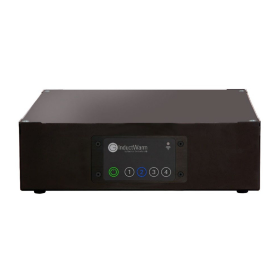
- Page 9 Mittels Infrarot-Fernbedienung (optional): Die Leistungsstufe kann optional mit der Infrarot- Fernbedienung eingestellt werden. Dazu muss die Fernbedienung in die Nähe (ca. 20-30cm Abstand) des Infrarot Empfängers der externen Bedieneinheit oder direkt zum Gerät gehalten werden. Bedienpanel Anzeige Funktion ON/OFF Taste leuchtet rot Gerät wird mit Strom versorgt ON/OFF Taste leuchtet grün Gerät ist im Stand-by-Betrieb...
- Page 10 Anschlüsse Die BUS-, Netzwerk- und USB- Anschlüsse befinden sich auf der Unterseite des InductWarm 130+ Gerätes: ® Anschluss externe InductWarm ® USB-Anschluss Bedieneinheit BUS-Anschlüsse BUS Kopplung / Netzwerkbetrieb Wird das InductWarm ® 130+ in einem Netzwerk betrieben, muss an einem beliebigen Gerät im Netzwerk eine externe Bedieneinheit und ein BUS-Kabel zu den anderen Geräten angeschlossen werden.
-
Page 11: Einbauzeichnungen
USB-Anschlüsse Über den USB-Anschluss können sowohl Software-Updates wie auch Systemparameter geladen und ausgelesen werden. Diese Aufgaben dürfen nur von ausgebildetem Servicepersonal ausgeübt werden. Reinigung / Wartung Das InductWarm 130+ ist für den Betrieb unter einer entsprechenden Abdeckung bestimmt und wird im ®... - Page 12 Anordnung mehrerer Geräte nebeneinander (Masse in mm) Die Panels sind zur Front gerichtet. Der Abstand zwischen den Geräten muss mindestens 25mm betragen. Anordnung mehrerer Geräte hintereinander (Masse in mm) Die Panels sind zur Seite gerichtet. Der Abstand zwischen den Geräten muss mindestens 25mm betragen.
- Page 13 HINWEIS: Es wird empfohlen, die Ausdehnung des Trägermaterials mit einer umgehenden Silikonfuge zu kompensieren. Beachten Sie dazu die Einbauempfehlungen unten. • HINWEIS: Gastros gibt gerne Empfehlungen bei der Wahl des Trägermaterials ab, übernimmt jedoch keine Haftung bei Schäden am Trägermaterial. Mit umgehender Silikonfuge (Empfehlung Gastros Switzerland) 3 mm umlaufende Deckplatte (z.B.
- Page 14 Einbauschnitt Detail • HINWEIS: Der Absatz muss beim Einbau absolut plan sein. Ist die Abdeckplatte einer mechanischen Spannung ausgesetzt, kann diese bei Erwärmung zu Rissen oder gar zum Bruch der Platte führen. • HINWEIS: Es wird empfohlen als Auflage der Induktions-Abdeckplatte kein Holz zu verwenden, da sich Holz bei Feuchtigkeit und Hitze ausdehnt und die weiter oben beschriebene, plane Auflage der Platte nicht mehr gegeben ist.
- Page 15 Gehäuse Abmessungen (in mm) Externe Bedieneinheit...
- Page 16 Montage-Kit Belüftung Die Lüftungsschlitze dürfen nicht verdeckt werden. Die Luftansaugtemperatur muss unter 40° C liegen. Die Geräterückseite (Luftauslassbereich) muss einen Abstand von mindestens 8,5 cm zum nächsten Objekt aufweisen und der Bodenlüfter muss min. 20 cm frei sein. Buffet-Beispiel...
-
Page 17: Allgemeine Informationen
Einbaubeispiel Flexible Abstände der Geräte Der Unterbau der InductWarm ® Elemente benötigt keine direkte Verbindung zueinander. Sie können also mit flexiblen Abständen angeordnet werden. Warm Kalt Warm Kalt Warm Kalt Allgemeine Informationen Warmhalten mit Induktion Die unter der Deckplatte (1) liegende Induktionsspule (2) generiert ein wechselndes elektromagnetisches Feld (3), das durch den Wirbelstromeffekt direkt im Gefässboden eines induktionsfähigen Aufsatzes Wärme (4) erzeugt. - Page 18 Die Werksgarantie umfasst Konstruktions-, Produktions- und Materialfehler. Weitergehende Ansprüche, insbesondere Defekte durch fehlerhafte Bedienung, sind ausgeschlossen. Alle Angaben und Hinweise in dieser Anleitung wurden unter Berücksichtigung der geltenden Normen und Vorschriften zusammengestellt. Die Gastros Switzerland AG übernimmt keine Haftung für Schäden aufgrund: • Nichtbeachtung der Anleitung •...
- Page 19 Induktionsgerät nicht geöffnet werden. Im Inneren des Gerätes befinden sich KEINE vom Benutzer zu wartenden Teile. Eine Reparatur darf nur von autorisiertem Servicepersonal durchgeführt werden. Wenden Sie sich an Ihren Fachhändler, einen ausgebildeten Gastros Service-Partner oder nehmen Sie mit unserem Kundendienst Kontakt auf: servicepoint@gastros.swiss...
-
Page 20: Sicherheitsbestimmungen
Sicherheit verantwortliche Person genau instruiert und beim Gebrauch des Geräts überwacht werden. Gastros Switzerland AG lehnt jegliche Haftung aufgrund von eigenmächtigen Umbauten oder Modifikationen ab. Wenn die Netzanschlussleitung des Geräts beschädigt wird, muss sie durch den Hersteller ersetzt werden, um Gefährdungen zu vermeiden. -
Page 21: Störungsbehebung
Steckerverbindung überprüfen, Gerät nicht eingeschaltet Gerät einschalten mittels Ein- / Ausschalter am Geräteboden Kundendienst informieren Gerät defekt servicepoint@gastros.swiss Aufsatz/Gefäss ist zu klein, falsch Keine Hitze, Leistungstaste 1, Aufsatz/Gefäss wird nicht positioniert oder nicht 2, 3 oder 4 blinkt blau erkannt... -
Page 22: Technische Daten
Technische Daten Technische Informationen / InductWarm 130+ Undercounter Element ® Spannungsbereich 100-240 VAC Frequenz (Netz) 50/60 Hz Induktionsfrequenz 18-25 kHz Maximale Leistung 800 W Interne Absicherung 10 A Masse / Gewicht 350 x 350 x 110 mm / 5,6 kg Anschluss-Typ Zertifizierung... - Page 23 InductWarm 130+ ® Undercounter Original instructions Operating and assembly manual Version 02/2022...
-
Page 24: Introduction
Reflection heat from the dish’s bottom is the only source of heat to the surface. As a result, the cover material expands. However, with the right choice of material, this expansion can be reduced to a minimum. Gastros can assist you by selecting the right cover material. - Page 25 Overview of accessories Use only original accessories from Gastros Switzerland! CAUTION – Risk of fire and electric shock. Only replace power cord (No. 3) with original cable by the manufacturer: Article No.: 6 01 10x xx Cabling (example) The power supply (POWER side) is independent of the BUS coupling (BUS side). Each unit must be connected to electrical power, either directly via a power cord (3) as seen with devices A and D or indirectly via a power chain cable (8) as seen with devices B and C.
- Page 26 Power supply You can link up to three InductWarm 130+ units with the power chain cable (Article No. 6 10 1xx 00) and ® connect them with the power cord (article 6 01 10x 00) to a power outlet 100-240 VAC (16 A). When using a power outlet with only 10A, you can link up to two InductWarm 130+ devices.
- Page 27 Using the infrared remote control (optional): The power level can optionally be set with the infrared remote control. To do this, the remote control must be held close (approx. 20-30 cm / 8-12”) to the infrared receiver of the external control panel or directly to the internal panel of the device. Control panel display Function ON/OFF button lights up red...
- Page 28 Connectors BUS, network and USB connections are located on the underside of the InductWarm 130+ unit: ® Connection external InductWarm ® USB connection control panel BUS coupling / network mode If a certain number of InductWarm 130+ units should be operated within a network, one chosen unit of the ®...
-
Page 29: Built-In Drawings
USB connection Both software updates and system parameter updates can be loaded via the USB port. This task should only be performed by trained service staff. Cleaning / maintenance The InductWarm 130+ is intended to be installed underneath a cover plate and is normally operated via an ®... - Page 30 Arrangement of several devices next to each other 20mm / 0,8” The panels face the front. The distance between the devices must be at least 25 mm/0,98”. Arrangement of several devices one behind the other 20mm / 0,8” The panels are facing to the side. The distance between the devices must be at least 25 mm/0,98”.
- Page 31 Cross section Using natural stone (which Gastros does NOT recommend), artificial stone and glass as a cover material can cause expansion when heated, and this can lead to tension cracks. • PLEASE NOTE: Gastros recommends using an immediate silicone joint for any potential extension of the surface.
- Page 32 Installation detail • PLEASE NOTE: The edge must be absolutely flat when installed. If the cover plate is subjected to mechanical tension, this can lead to cracks or even breakage of the plate when heated. • PLEASE NOTE: It is recommended not to use wood as a support for the induction cover plate, as wood expands with moisture and heat and the flat support of the plate described above is no longer given.
- Page 33 Device dimensions Dimensions in mm Dimensions in inch 11,81 0,71 External control panel 2,32” 1,67” 0,98” 1,38” 0,14” 4,72” 5,51”...
- Page 34 Mounting kit Dimensions in mm Dimensions in inch Air circulation Air circulation openings must not be covered by any other installation parts. The surrounding air must not be higher than 40 °C/104 °F. The back side fan must have 8.5 cm/3.35” of open space, and the bottom fan must have 20 cm/7.87”...
-
Page 35: General Information
Built-in example Flexible distances of the induction units The substructures for fixing the InductWarm units do not require a direct connection to one another. As a result, ® the induction units can be arranged with flexible spacing. Warm Cold Warm Cold Warm Cold... - Page 36 Dishes PLEASE NOTE: Only use induction-capable, appropriately marked dishes. Incorrect and damaged dishes can be dangerous for the InductWarm device! The use of dishes without moist ® food can lead to excessive heating of the power electronics and reduce their service life. If the dishes overheat by bringing them to a high temperature when they are empty or used without moist food, the characteristics of the dish’s material can also change.
- Page 37 There are NO user-serviceable parts inside. Repairs may only be carried out by authorized service personnel. Contact your dealer, a trained Gastros Switzerland AG Service Partner, or our customer service department via servicepoint@gastros.swiss.
-
Page 38: Safety Regulations
Gastros Switzerland AG disclaims all liability in cases of unauthorized conversions or modifications by the customer. If the main supply cable for the appliance is damaged, it must be replaced by the manufacturer, an authorized service agent or another similarly qualified individual in order to prevent hazards. -
Page 39: Troubleshooting
Contact customer service Device is defect servicepoint@gastros.swiss No heat, power level button 1, Dish is too small, incorrectly placed or Dish is not detected 2, 3 or 4 is flashing blue... -
Page 40: Technical Data
Technical Data Technical information / InductWarm 130+ undercounter unit ® Voltage range 100-240 VAC Power frequency 50/60 Hz Induction frequency 18-25 kHz Maximum power 800 W Internal electrical fuse protection 10 A 350 x 350 x 110 mm / 5,6 kg Dimensions / weight 13,78“... - Page 41 InductWarm 130+ ® Undercounter Instructions originales Instructions d'utilisation et de montage Version 02/2022...
-
Page 42: Introduction
être maintenus parfaitement au chaud. La chaleur réfléchie par l’ustensile peut entraîner une dilatation du matériau de revêtement. Avec le bon choix de matériau, cette dilatation peut être limitée au minimum ou complètement réduite. Gastros se fera un plaisir de vous conseiller sur le choix du meilleur revêtement. - Page 43 Vue d’ensemble des accessoires N'utilisez que des pièces d'origine de Gastros Suisse ! AVERTISSEMENT : Risque d'incendie et de choc électrique. Remplacez uniquement le câble d'alimentation (n° 3) par le câble d'origine du fabricant : N° d'article : 6 01 10x xx Raccordement (exemple) L'alimentation (POWER-Side) est indépendante de la connexion BUS (BUS-Side).
- Page 44 Alimentation électrique Un maximum de trois éléments InductWarm 130+ peuvent être raccordés avec un câble de communication ® (article 6 10 1xx 00) et fonctionner avec un seul câble d'alimentation (article 6 01 10x 00) sur une prise 100-240 VAC (16 A). Sur une prise avec 10 A seulement deux éléments peuvent être raccordés. Un élément à induction consomme au maximum 800 W.
- Page 45 Au moyen de la télécommande infrarouge (en option) : Le niveau de puissance peut être ajusté en appuyant sur la télécommande infrarouge. Pour ce faire, la télécommande doit être dirigée vers le récepteur infrarouge de l'unité de commande externe (à une distance d'environ 20-30 cm) ou directement vers l'appareil. LED d’état Fonction Le bouton ON / OFF s'allume en rouge...
- Page 46 Connexions Les connexions BUS, réseau et USB sont situées sous l'appareil InductWarm 130+ : ® Connexions Connexion de l'externe Connexion USB InductWarm Unité de contrôle ® Connexion BUS / fonctionnement en réseau Si l'appareil InductWarm 130+ fonctionne en réseau, une unité de commande externe doit être raccordée à ®...
-
Page 47: Plans D'installation
Ports USB Les mises à jour logicielles et les paramètres système peuvent être chargés via le port USB. Ces tâches ne doivent être effectuées que par du personnel de maintenance qualifié. Nettoyage et maintenance L'InductWarm 130+ est conçu pour fonctionner sous un couvercle et est normalement commandé via un ®... - Page 48 Disposition de plusieurs appareils les uns à côté des autres (dimensions en mm) Les unités de contrôle font face à l'avant. La distance entre les appareils doit être d'au moins 25 mm. Disposition de plusieurs appareils les uns derrière les autres (dimensions en mm) Les unités de contrôle sont tournées vers le côté.
- Page 49 Vue en coupe La pierre naturelle (l'utilisation n'est pas recommandée par Gastros), la pierre artificielle et le verre comme matériau de revêtement se dilatent lorsqu'ils sont chauffés, ce qui peut entraîner des fissures sous contrainte. REMARQUE : Il est recommandé de compenser la dilatation du matériau de revêtement avec un joint •...
- Page 50 Détail de la coupe de montage • REMARQUE: Lors du montage, le palier doit être absolument plan. Une plaque de recouvrement qui est soumis à une tension mécanique peut subir des fissures ou même des cassures en cas d’échauffement. • REMARQUE: Il est recommandé...
- Page 51 Dimensions de l'appareil (en mm) L’unité de commande externe...
- Page 52 Kit de montage Aération Les fentes d'aération ne doivent pas être couvertes. La température de l'air ambiant doit être inférieure à 40 °C. Il faut prévoir un dégagement d'au moins 8,5 cm entre l'arrière de l'appareil (zone de sortie d'air) et le mur ou l'objet adjacent, et un espace libre d'au moins 20 cm sous le ventilateur du bas de l'appareil.
-
Page 53: Informations Générales
Example d‘installation Distances flexibles entre les appareils La sous-structure des éléments InductWarm ne nécessite pas de connexion directe les uns aux autres. Ainsi, ils ® peuvent être disposés avec un espacement flexible. Chaud Froid Chaud Froid Chaud Froid Informations générales Maintien au chaud avec l'induction La bobine d'induction (2) située sous le matériau de revêtement (1) génère un champ électromagnétique alternant... - Page 54 à un mauvais fonctionnement, sont exclues. Toutes les informations et instructions contenues dans cette notice ont été formulées en tenant compte des normes et réglementations en vigueur. Gastros Switzerland AG n'assume aucune responsabilité pour les dommages dus à : •...
- Page 55 à induction ne doit pas être ouvert. Il n'y a AUCUNE pièce réparable par l'utilisateur à l'intérieur. Les réparations ne doivent être effectuées que par du personnel de maintenance autorisé. Adressez-vous à votre revendeur, un partenaire de service Gastros qualifié ou contactez notre service clientèle : servicepoint@gastros.swiss...
- Page 56 Gastros Switzerland AG décline toute responsabilité par suite de transformations ou modifications non autorisées. Si le cordon d'alimentation de l'appareil est endommagé, il doit être remplacé par le fabricant pour éviter tout danger.
-
Page 57: Dépannage
Contacter le service clientèle Appareil défectueux servicepoint@gastros.swiss Pas de chaleur, le bouton 1, 2, 3 ou Le récipient est trop petit, mal placé ou Le récipient n’est pas détecté 4 clignote en bleu n'est pas compatible avec l'induction La pile est déchargée... -
Page 58: Caractéristiques Techniques
Caractéristiques techniques Informations techniques / Élément encastrable InductWarm ® 130+ Plage de tension 100-240 VAC Fréquence (réseau électrique) 50/60 Hz Fréquence d'induction 18-25 kHz Puissance maximale 800 W Protection interne 10 A Dimensions / poids 350 x 350 x 110 mm / 5,6 kg Type de raccordement Certification... -
Page 59: Zertifikation - Certifications - Certificats
Zertifikation – Certifications – Certificats EC Declaration of Conformity IECEE Certificat... - Page 60 Kontakt / Contact Gastros Switzerland AG | Buckhauserstrasse 1 | 8048 Zurich / Switzerland www.gastros.swiss | servicepoint@gastros.swiss Die Angaben zu den jeweiligen Produkten entsprechen den zum Zeitpunkt der Drucklegung vorhandenen Kenntnissen. Abweichungen in Farbe und Form von Abbildungen, Irrtümer und Druckfehler, sowie Änderungen bleiben vorbehalten.