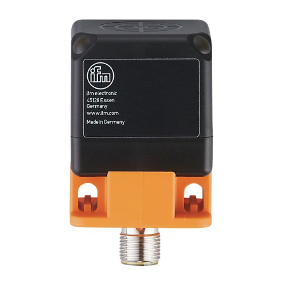
IFM Electronic efector100 IM5142 Notice De Montage
Masquer les pouces
Voir aussi pour efector100 IM5142:
- Notice d'utilisation (39 pages) ,
- Notice d'utilisation originale (21 pages) ,
- Notice de montage (5 pages)
Table des Matières
Publicité
Les langues disponibles
Les langues disponibles
Liens rapides
Publicité
Table des Matières

Sommaire des Matières pour IFM Electronic efector100 IM5142
- Page 1 Montageanleitung Induktiver Sensor IMC, nicht bündig mit Analogausgang Installation instructions Inductive sensor IMC, non flush with analogue output Notice de montage Détecteur de proximité inductif IMC, non encastrable á sortie analogique...
-
Page 2: Bestimmungsgemäße Verwendung
Bestimmungsgemäße Verwendung Der induktive Sensor mit Analogausgang erfasst berührungslos den Abstand zwischen Objekt und aktiver Sensorfläche. Arbeitsbereich (s) siehe Geräteaufkle- ber (Werte nach Norm-Messung auf ST 37; bei anderen Metallen entsprechend Korrekturfaktor). Das analoge Normsignal ist je nach Gerätetyp ein Spannungs- (0...10 V) oder Stromsignal (4...20 mA). -
Page 3: Aktive Fläche Ausrichten
Aktive Fläche ausrichten Die aktive Fläche ist im Auslieferungszustand nach vorn gerichtet (Abb. 5). Durch Lösen der Befestigungsschraube und Drehen des Sensorblocks (Abb. 5-8) kann die aktive Fläche seitlich ausgerichtet werden (Abb. 8). 90° 180° Elektrischer Anschluss Das Gerät darf nur von einer Elektrofachkraft installiert werden. Befolgen Sie die nationalen und internationalen Vorschriften zur Errichtung elektrotechnischer Anlagen. - Page 4 Betrieb LED grün. Leuchtet, wenn Versorgungsspan- nung anliegt. LED gelb. Leuchtet konstant, wenn sich das Objekt im Arbeitsbereich befindet. Außerhalb des Arbeitsbereiches beginnt die LED zu blinken. Ausgangskennlinien (schematisch) Arbeitsbereich (s) → LED leuchtet konstant Warn-/ Fehlerbereich → LED blinkt = Anfangspunkt Arbeitsbereich = Endpunkt Arbeitsbereich Der Betrieb des Sensors ist wartungsfrei.
-
Page 5: Function And Features
Function and features Inductive proximity switches with analogue output determine without contact the distance between object and sensing face. For the operating range (s) see the label of the unit (values are to standard mild steel targets, for other metals cor- rection factors apply). -
Page 6: Alignment Of The Sensing Face
Alignment of the sensing face On delivery, the sensing face is facing the front (fig. 5). The sensing face can be turned to the side (fig. 8) by loosening the fixing screw and turning the sensor block (fig. 5-8). 90° 180°... -
Page 7: Set-Up / Operation
Set-up / Operation Green LED. Lights when supply voltage is applied. Yellow LED. Is lit permanently when the object is in the operating range. The LED starts to flash outside the operating range. Output characteristics (diagram) Operating range (s) → LED is lit permanently Warning / fault range →... -
Page 8: Fonctionnement Et Caractéristiques
Fonctionnement et caractéristiques Le détecteur de proximité inductif à sortie analogique détecte sans contact la distance entre l'objet et la face active. La zone de fonctionnement (s) est indiquée sur l'étiquette de l'appareil (valeurs selon la mesure normalisée sur acier doux, pour d'autres métaux des facteurs de correction doivent être appliqués). -
Page 9: Orientation De La Face Active
Orientation de la face active A la livraison, la face active est orientée de manière frontale (fig. 5). La face active peut être orientée latéralement (fig. 8) en desserrant la vis de fixation et en tournant le bloc détecteur (fig. 5-8). 90°... -
Page 10: Mise En Service / Fonctionnement
Mise en service / Fonctionnement LED verte : allumée lorsque la tension d'alimentation est appliquée. LED jaune : allumée continuellement si l'objet se trouve dans la zone de fonctionnement. En dehors de la zone de fonctionnement la LED commence à clignoter. Caractéristique sortie (diagramme) Zone de fonctionnement (s) →...


