Publicité
Les langues disponibles
Les langues disponibles
Publicité
Table des Matières

Manuels Connexes pour LUMENE ShowPlace HD


Sommaire des Matières pour LUMENE ShowPlace HD
- Page 1 Mode d’emploi User manual Update : 12/09/2018 www.lumene-screens.com...
- Page 3 Mode d’emploi User manual Français..............4 English ..............14...
-
Page 4: Table Des Matières
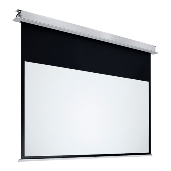
Félicitations et merci d’avoir choisi cet écran de projection LUMENE. Cet écran a été créé pour vous offrir une image claire, lumineuse et contrastée. Il est également d’une grande fiabilité et très simple d’emploi. Cet écran a été conçu pour être installé dans tous types de faux-plafonds. Il doit être installé à l’endroit le plus approprié... -
Page 5: Schémas Et Dimensions
SCHÉMAS ET DIMENSIONS Support de fixation Support de fixation Cache plafond Cache plafond distance entre les trous de montage 104 mm Dimensions de découpe Longueur de découpe : L - 25 mm Largeur de découpe : 115 mm Hauteur du plafond : >122 mm 119 mm 200C 240C... -
Page 6: Installation
INSTALLATION Découper le faux-plafond en fonction de la taille de l’écran (voir le tableau page précédente). Repérer l’emplacement des vis de montage sur le carter, puis marquer l’emplacement sur le plafond. Trou de fixation Percer le plafond aux emplacements marqués, puis placer des chevilles de fixation (non fournies). Couper les tiges filetées à... - Page 7 Présenter l’écran sous l’ouverture du faux-plafond, brancher l’alimentation, puis insérer les tiges filetées dans les emplacements prévus sur les côtés du carter. Tout en maintenant l’écran horizontal, serrer les écrous anti-chute. Vérifier à l’aide d’un niveau que l’écran est bien droit et aligné au faux-plafond, puis serrer les écrous de blocage. Écrou anti-chute Écrou de blocage •...
- Page 8 Connecter le cache de plafond gauche à l’interface IR. Interface IR Positionner les 2 caches de part et d’autre de Vérifier que les 2 caches sont alignés avec le l’écran, vérifier que l’espace disponible est carter et le plafond, puis pousser fermement identique de chaque côté.
-
Page 9: Méthodes De Commande
MÉTHODES DE COMMANDE Interface RS485/RS232 et contact sec Commande manuelle Interface IR Télécommande IR / Télécommande RF (en option) Fonctionnement • Appuyer sur le bouton « up » pour faire remonter l’écran. • Appuyer sur le bouton « stop » pour arrêter l’écran. •... - Page 10 Commande manuelle STOP Le bouton de contrôle manuel est situé sur la gauche du carter et fonctionne en cycle. DOWN STOP Contrôle externe EXTERNAL Brancher le connecteur RJ12 6P6C. CTRL De gauche à droite : - 3-6 : câble de contrôle DOWN - 3 : câble commun RJ12...
-
Page 11: Réglage Des Butées (Extra-Drop)
RÉGLAGE DES BUTÉES BASSES ET HAUTES (EXTRADROP) L’extradrop est la zone noire de la toile d’un écran Lumene située au-dessus de EXTRADROP la zone de projection. La hauteur de cette bande noire peut être ajustée afin de positionner verticalement la zone de projection. - Page 12 JAUNE Réglage de la butée de déroulement (butée basse / Extradrop) - Vis Sens horaire : butée plus haute Sens anti-horaire : butée plus basse Pour ce réglage, l’action n’est pas Pour réglage, l’action directement visible sur la toile. Il faut directement visible toile...
-
Page 13: Garantie
- Ne rien placer ou accrocher sur l’écran lorsque celui-ci est déployé. - Ne pas mettre votre doigt à l’intérieur du carter quand vous rétractez la toile Tous les produits LUMENE sont garantis deux ans à partir de la date d’achat, de l’écran. - Page 14 Congratulations and thank you for choosing a LUMENE projection screen. This screen has been designed to offer a clear, bright and contrasted image. It is also of a great reliability and very easy to use. This screen has been designed to fit all types of suspended ceilings. It should be installed at the most proper place where it can work with projector.
- Page 15 DIAGRAMS & DIMENSIONS Right bracket Left bracket Right end cap Left end cap installation distance 104 mm Ceiling cutout size Cutout length : L - 25 mm Cutout width : 115 mm Ceiling height : > 122 mm 119 mm 200C 240C 270C...
- Page 16 INSTALLATION Cut the suspended ceiling based on the screen size (see chart on previous page). Locate the screw holes on the case, then mark the position on the ceiling. Screw hole Drill holes in the ceiling on the marked positions. Insert dowels in the drilled holes (not provided). Cut the threaded rod at desired height and screw them in the ceiling.
- Page 17 Hold the screen under the suspended ceiling hole, connect the power, and insert the threaded rods in the dedicated holes on the sides of the case. While holding the screen horizontally, twist the anti-fall nuts. Using a spirit level, check the screen is well positioned and aligned with the suspended ceiling, then tighten the lock nuts.
- Page 18 Connect the left end cap to the IR interface. IR interface Place both end caps on both sides of the screen, Check both end caps are aligned with case and and check the available space is identical on suspended ceiling, then push firmly to clip them each side.
- Page 19 CONTROL METHODS RS485/RS232 interface and dry control Manual control IR interface IR remote control / RF remote control (optional) Daily use • Press « up » to retract the screen • Press « stop » to stop the screen • Press « down » to lower the screen Pairing : •...
- Page 20 Manual control STOP Manual control button is a cycle control button and is located on the left side of the case. DOWN STOP External control EXTERNAL Plug RJ12 6P6C connector. CTRL From left to right : - 3-6 : control signal cable DOWN - 3 : common cable RJ12...
- Page 21 LOWER & UPPER STOPS SETTINGS (EXTRADROP) The extradrop is the black zone of a Lumene screen located above the projection EXTRADROP area. The height of this black zone can be adjusted so you can position the projection area vertically. PROJECTION AREA ATTENTION : •...
- Page 22 YELLOW Adjusting the lowering stop (lower stop / Extradrop) - screw Clockwise : upper stop Counter-clockwise : lower stop This adjustment will not be directly This adjustment is directly visible visible on the screen. You will first because screen relows need to make the adjustment, and successive notches.
- Page 23 The warranty is strictly limited to the country of the original purchase. Warranty related expenses: LUMENE will take charge of all the expenses on parts and labor related to the repair or the replacement of the products. The expenses related to the shipping and insurance fees will be shared as described below.
- Page 24 Mise à jour : 12/09/2018...