Table des Matières
Publicité
Les langues disponibles
Les langues disponibles
Liens rapides
Instructions for use and installation
GB
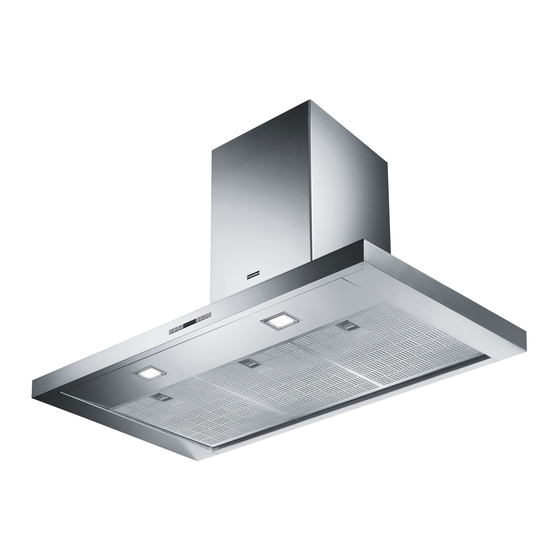
Cooker Hood
Istruzioni per l'uso e l'installazione
IT
Cappa
Mode d'emploi et installation
FR
Hotte de Cuisine
Bedienungsanleitung und Einrichtung
DE
Dunstabzugshaube
Kullanım ve montaj talimatları
TR
Davlumbaz
Uživatelská Pøíruèka
CZ
Odsavač par
FDF 9274 I XS
FDF 12274 I XS
Publicité
Table des Matières

Manuels Connexes pour Franke FDF 9274 I XS


Sommaire des Matières pour Franke FDF 9274 I XS
- Page 1 Instructions for use and installation Cooker Hood Istruzioni per l’uso e l’installazione Cappa Mode d’emploi et installation Hotte de Cuisine Bedienungsanleitung und Einrichtung Dunstabzugshaube Kullanım ve montaj talimatları Davlumbaz Uživatelská Pøíruèka Odsavač par FDF 9274 I XS FDF 12274 I XS...
-
Page 2: Table Des Matières
INDEX RECOMMENDATIONS AND SUGGESTIONS ........................3 CHARACTERISTICS ................................4 INSTALLATION..................................6 USE ...................................... 10 MAINTENANCE ................................... 11 INDICE CONSIGLI E SUGGERIMENTI............................13 CARATTERISTICHE................................14 INSTALLAZIONE ................................. 16 USO...................................... 20 MANUTENZIONE ................................21 SOMMAIRE CONSEILS ET SUGGESTIONS............................23 CARACTERISTIQUES................................. 24 INSTALLATION..................................26 UTILISATION .................................. -
Page 23: Conseils Et Suggestions
CONSEILS ET SUGGESTIONS La présente notice d' e mploi vaut pour plusieurs versions de l' a ppareil. Elle peut contenir des descriptions d' a c- cessoires ne figurant pas dans votre appareil. INSTALLATION • Le fabricant décline toute responsabilité en cas de dommage dû à une installation non correcte ou non conforme aux règles de l’art. -
Page 24: Caracteristiques
CARACTERISTIQUES Encombrement 2 24... - Page 25 Composants Réf. Q.té Composants de Produit Corps Hotte équipé de: Comandes, Lumière, Filtres Cheminée Télescopique formée de : Cheminée Supérieure Cheminée Inférieure Treillis télescopique avec Aspirateur, formé par: 7.1a Treillis supérieur 7.1b Treillis inférieur Flasque de Réduction ø 150-120 mm 14.1 Rallonge Raccord Sortie Air Raccord Sortie Air...
-
Page 26: Installation
INSTALLATION Perçage Plafond/Étagère et Fixation Treillis PERÇAGE PLAFOND/ETAGERE • À l’aide d’un Fil à plomb, reporter sur le Plafond/Étagère de support le centre du Plan de Cuisson. • Poser contre le Plafond/Étagère le Gabarit de Perçage 21 fourni avec l’appareil, en faisant coïncider son centre avec le centre projeté... -
Page 27: Avant De Serrer Définitivement Les Vis, Il Est Possible
FiXATION TREILLIS • Dévisser les deux vis qui fixent la cheminée inférieure et sor- tir cette dernière du treillis (depuis la partie inférieure). • Dévisser les deux vis qui fixent la cheminée supérieure et sortir cette dernière du treillis (depuis la partie supérieure). Si l’on souhaite régler la hauteur du treillis, effectuer les opéra- tions suivantes: •... - Page 28 Branchements SORTIE AIR VERSION ASPIRANTE En cas d’installation en version aspirante, brancher la hotte à la ø 150 ø 120 tuyauterie de sortie via un tube rigide ou flexible de ø 150 ou 120 mm, au choix de l’installateur. • En cas de branchement avec un tube de ø120 mm, insérer le flasque de réduction 9 sur la sortie du corps de la hotte.
-
Page 29: Connexion Électrique
Montage Cheminée - Montage Corps Hotte • Positionner la Cheminée supérieure et fixer cette dernière dans la partie supérieure du Treillis à l’aide de 2 Vis 12c (2,9 x 6,5) fournies avec l’appareil. • De la même façon, positionner la Cheminée inférieure et fixer cette dernière dans la partie inférieure du Treillis à... -
Page 30: Utilisation
UTILISATION Tableau de commande Touche Fonction Affichage Branche et débranche le moteur d’aspiration à la Affiche la vitesse réglée première vitesse Diminue la vitesse d’exercice. Affiche la vitesse réglée Augmente la vitesse d’exercice. Affiche la vitesse réglée Active la vitesse Intensive à partir de n’importe Affiche alternativement HI et le temps restant une quelle vitesse, même lorsque le moteur est éteint. -
Page 31: Entretien
ENTRETIEN TELECOMMANDE (FOURNIE SUR DEMANDE) Il est possible de commander cet appareil au moyen d’une télé- commande, alimentée avec des piles alcalines zinc-charbon 1,5 V du type standard LR03-AAA (non compris). • Ne pas ranger la télécommande à proximité de sources de cha- leur. -
Page 32: Filtres Anti-Odeur Au Charbon Actif (Version Filtrante)
Filtres anti-odeur au charbon actif (version filtrante) Non lavable et non régénérable, il doit être remplacé à l’affichage de FC ou au moins tous les 4 mois. Le signal d’alarme, si préalablement activé, a lieu seulement lorsque le moteur d’aspiration est en marche. Activation du signal d’alarme •... - Page 64 991.0282.579_ver1...