Table des Matières
Publicité
Les langues disponibles
Les langues disponibles
Liens rapides
Montageanleitung
DE
Installation instructions
GB
Instructions de montage
FR
Istruzioni di montaggio
IT
Installationsvejledning
DK
Montagehandleiding
NL
Manual de montaje
ES
Instrukcja montażu
PL
HEP 25-180-10
HEP 25-180-10
HEP 25-180-10
HEP 25-180-10
HEP 25-180-10
HEP 25-180-10
HEP 25-180-10
HEP 25-180-10
Publicité
Table des Matières

Manuels Connexes pour BRÖTJE HEP 25-180-10

Sommaire des Matières pour BRÖTJE HEP 25-180-10
- Page 1 HEP 25-180-10 Montageanleitung Installation instructions HEP 25-180-10 HEP 25-180-10 Instructions de montage HEP 25-180-10 Istruzioni di montaggio Installationsvejledning HEP 25-180-10 Montagehandleiding HEP 25-180-10 HEP 25-180-10 Manual de montaje HEP 25-180-10 Instrukcja montażu...
-
Page 2: Table Des Matières
Inhaltsverzeichnis Zu dieser Anleitung................... Inhalt dieser Anleitung................Verwendete Symbole................. An wen wendet sich diese Anleitung?............Lieferumfang.................... Sicherheit....................Bestimmungsgemäße Verwendung............Allgemeine Sicherheitshinweise..............Montage....................Überblick....................Montage im WGB 50-70 E................Montage im WGB 90-110 E................ Elektrische Installation................10 Inbetriebnahme..................11 Voreinstellung..................11 Nutzung als Heizkreispumpe.............. - Page 3 Utilisation conforme aux fins prévues............31 Consignes générales de sécurité..............31 Montage....................32 Aperçu...................... 32 Montage dans la WGB 50-70 E..............33 Montage dans la WGB 90-110 E..............33 Branchement électrique (général)............... 34 Mise en service..................35 Préréglage....................35 Utilisation comme pompe de circuit de chauffe..........35 Utilisation comme pompe à...
- Page 4 Idrifttagning..................... 59 Forindstilling..................... 59 Anvendelse som varmekredspumpe............59 Anvendelse som kedelpumpe..............60 Rest løftehøjde-Diagram................64 Pumpemodulation..................65 Inhoudsopgave Toelichting bij deze handleiding..............66 Inhoud van deze handleiding..............66 Gebruikte symbolen.................. 66 Tot wie richt zich deze handleiding?............66 Leveringsomvang..................66 Veiligheid....................
- Page 5 Spis treści Uwagi dotyczące niniejszej instrukcji montażu..........90 Treść niniejszej instrukcji montażu.............. 90 Zastosowane symbole................90 Dla kogo przeznaczona jest niniejsza instrukcja montażu?......90 Zakres dostawy..................90 Bezpieczeństwo..................91 Zastosowanie zgodnie z przeznaczeniem............. 91 Ogólne wskazówki dotyczące bezpieczeństwa..........91 Montaż....................92 Ogólna informacja..................
-
Page 6: Zu Dieser Anleitung
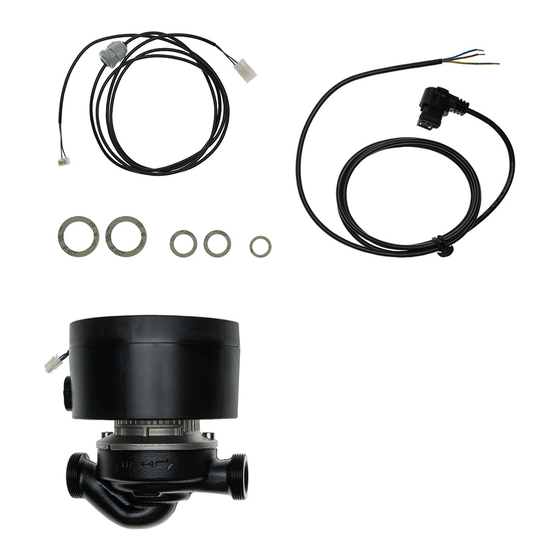
1.3 An wen wendet sich diese Anleitung? Diese Montageanleitung wendet sich an den Heizungsfachmann, der das Zubehör montiert. 1.4 Lieferumfang - Drehzahlgeregelte Pumpe HEP 25-180-10 - Netzleitung - PWM-Leitung - 2 Dichtungen 1" - 1 Dichtung 3/4" - 2 Dichtungen 1 1/2"... -
Page 7: Sicherheit
Gefahr! Beachten Sie unbedingt die folgenden Sicherheitshinweise! Sie gefährden sonst sich selbst und andere. 2.1 Bestimmungsgemäße Verwendung Die drehzahlgeregelte Pumpe HEP 25-180-10 dient zum Einbau in Gas-Brennwert- kessel der Serie WGB 50-110 E anstelle des Pumpenersatzrohrs. Alternativ kann die Pumpe auch extern installiert werden. 2.2 Allgemeine Sicherheitshinweise Stromschlaggefahr! Alle mit der Installation verbundenen Elektroarbeiten dürfen... -
Page 8: Montage
Montage 3. Montage 3.1 Überblick Stromschlaggefahr! Vor Durchführung der Montagearbeiten ist der Heizkessel spannungslos zu schalten und gegen Wiedereinschalten zu sichern! Abb. 1: Drehzahlgeregelte Pumpe HEP 25-180-10 Netzanschlussbuchse PWM-Anschlussstecker Drehzahlgeregelte Pumpe HEP 25-180-10 7303554-01B 07.11... -
Page 9: Montage Im Wgb 50-70 E
Lebensgefahr durch ausströmendes Gas! Vor Durchführung der Montagearbeiten ist die Gaszufuhr des Gas-Brennwertkessels zu schließen! Hinweis: Vor der Montage der Pumpe HEP 25-180-10 in Gas-Brennwertkessel der Serien WGB 90 E und WGB 110 E ist die Gasleitung zum Gasventil des Heizkessels zu entfernen, da sonst die obere Überwurfmutter nicht zugänglich ist. -
Page 10: Elektrische Installation
LMS anschließen - PWM-Leitung gemäß Abb. 3 am Ausgang P1 (PWM-Steuerausgang) der Rege- lung LMS anschließen Hinweis: Bei externer Montage sind für die Installation der Anschlussleitungen im Kessel die beiliegenden Verschraubungen zu verwenden. Drehzahlgeregelte Pumpe HEP 25-180-10 7303554-01B 07.11... -
Page 11: Inbetriebnahme
Minimale und maximale Pumpendrehzahl sind gemäß der Anlagenkonfiguration unter den Menüpunkten Heizkreis 1-Heizkreis 3 einzustellen Funktion Prog.-Nr. Einstellebene Einstellung Heizkreis 1 Pumpendrehzahl Minimum Pumpendrehzahl Maximum Heizkreis 2 Pumpendrehzahl Minimum 1182 Pumpendrehzahl Maximum 1183 Heizkreis 3 Pumpendrehzahl Minimum 1482 Pumpendrehzahl Maximum 1483 7303554-01B 07.11 Drehzahlgeregelte Pumpe HEP 25-180-10... -
Page 12: Nutzung Als Kesselpumpe
Pumpendrehzahl Minimum Pumpendrehzahl Maximum Heizkreis 2 Pumpendrehzahl Minimum 1182 Pumpendrehzahl Maximum 1183 Heizkreis 3 Pumpendrehzahl Minimum 1482 Pumpendrehzahl Maximum 1483 Kessel Pumpendrehzahl Minimum 2322 Pumpendrehzahl Maximum 2323 Trinkwasser-Speicher Pumpendrehzahl Minimum 5101 Pumpendrehzahl Maximum 5102 Drehzahlgeregelte Pumpe HEP 25-180-10 7303554-01B 07.11... - Page 13 Fühlereingang BX1 5892 Trinkwasserstellglied Q3 Minimale und maximale Pumpendrehzahl sind gemäß der Anlagenkonfiguration unter dem Menüpunkt Trinkwasser-Speicher einzustellen Funktion Prog.-Nr. Einstellebene Eingestellter Wert Trinkwasser-Speicher Pumpendrehzahl Minimum 5101 = 2322 Pumpendrehzahl Maximum 5102 = 2323 7303554-01B 07.11 Drehzahlgeregelte Pumpe HEP 25-180-10...
- Page 14 Pumpendrehzahl Minimum Pumpendrehzahl Maximum Heizkreis 2 Pumpendrehzahl Minimum 1182 Pumpendrehzahl Maximum 1183 Heizkreis 3 Pumpendrehzahl Minimum 1482 Pumpendrehzahl Maximum 1483 Kessel Pumpendrehzahl Minimum 2322 Pumpendrehzahl Maximum 2323 Trinkwasser-Speicher Pumpendrehzahl Minimum 5101 Pumpendrehzahl Maximum 5102 Drehzahlgeregelte Pumpe HEP 25-180-10 7303554-01B 07.11...
- Page 15 Bedarf Konfiguration PWM-Ausgang P1 6085 Kesselpumpe Q1 Anlagenfrostschutz 6120 Minimale und maximale Pumpendrehzahl sind gemäß der Anlagenkonfiguration unter dem Menüpunkt Kessel einzustellen Funktion Prog.-Nr. Einstellebene Eingestellter Wert Kessel Pumpendrehzahl Minimum 2322 Pumpendrehzahl Maximum 2323 7303554-01B 07.11 Drehzahlgeregelte Pumpe HEP 25-180-10...
-
Page 16: Restförderhöhe-Diagramme
Inbetriebnahme 4.4 Restförderhöhe-Diagramme Abb. 4: Restförderhöhe WGB 50 E mit Pumpe HEP 25-180-10 100 % 80 % 60 % 40 % 20 % Wassermassenstrom [m Abb. 5: Restförderhöhe WGB 70-110 E mit Pumpe HEP 25-180-10 100 % 80 % 60 %... -
Page 17: Pumpenmodulation
Die Regelung der Kessel WGB 50 - 110 E ist so voreingestellt, dass der Heizkreis 1 nach Bedarf versorgt wird. Die modulierende Pumpe ist jedoch durch die Einstel- lung "Keine" am PWM-Ausgang P1 standardmäßig ausgeschaltet. 7303554-01B 07.11 Drehzahlgeregelte Pumpe HEP 25-180-10... -
Page 18: Gb 1. About These Instructions
1.3 For whom is this manual intended? This installation manual is intended for the heating specialist, who installs the ac- cessory. 1.4 Standard delivery - Variable speed pump HEP 25-180-10 - Power cable - PWM cable - 2 gaskets 1" - 1 gasket 3/4"... -
Page 19: Safety
Otherwise you are endangering yourself and others. 2.1 Appropriate use The variable speed pump HEP 25-180-10 is intended to be installed in gas con- densing boilers in the Paramount three 60-115 E series instead of the pump re- placement pipe. Alternatively, the pump can be installed externally. -
Page 20: Installation
3.1 Overview Risk of electric shock! Prior to commencing any installation work, isolate the boiler from the power supply and safeguard against unintentional reconnection. Fig. 1: Variable speed pump HEP 25-180-10 Power supply socket PWM connector Variable speed pump HEP 25-180-10... -
Page 21: Installation In Paramount Three 60-80 E
Risk to life from escaping gas! Prior to commencing any installation work, isolate the gas supply to the gas condensing boiler. Note: Prior to installing the pump HEP 25-180-10 in gas condensing boilers in the Paramount three 95 E and WGB 115 E series, remove the gas line to the boiler gas valve to permit access to the upper union nut. -
Page 22: Electric Installation
Installation - Check connections for leaks - Install pump HEP 25-180-10 externally - To insulate the pump, fit insulation semi-shells if required 3.4 Electric installation Fig. 3: Connection diagram - Plug the mains plug into the pump power supply socket (see Fig. 1) - Plug the PWM cable into the pump PWM socket (see Fig. -
Page 23: Commissioning
Setting level Setting Heating circuit 1 Pump speed min Pump speed max Heating circuit 2 Pump speed min 1182 Pump speed max 1183 Heating circuit 3 Pump speed min 1482 Pump speed max 1483 7303554-01 07.11 Variable speed pump HEP 25-180-10... -
Page 24: Use As Boiler Pump
Pump speed max 1183 Heating circuit 3 Pump speed min 1482 Pump speed max 1483 Boiler Pump speed min 2322 Pump speed max 2323 DHW cylinder Pump speed min 5101 Pump speed max 5102 Variable speed pump HEP 25-180-10 7303554-01 07.11... - Page 25 Set the minimum and maximum pump speeds in accordance with the system con- figuration under menu item DHW cylinder Function Prog. no. Setting level Set value DHW cylinder Pump speed min 5101 = 2322 Pump speed max 5102 = 2323 7303554-01 07.11 Variable speed pump HEP 25-180-10...
- Page 26 Pump speed max 1183 Heating circuit 3 Pump speed min 1482 Pump speed max 1483 Boiler Pump speed min 2322 Pump speed max 2323 DHW cylinder Pump speed min 5101 Pump speed max 5102 Variable speed pump HEP 25-180-10 7303554-01 07.11...
- Page 27 Set the minimum and maximum pump speeds in accordance with the system con- figuration under menu item Boiler Function Prog. no. Setting level Set value Boiler Pump speed min 2322 Pump speed max 2323 7303554-01 07.11 Variable speed pump HEP 25-180-10...
-
Page 28: Residual Head Diagrams
Fig. 4: Residual head Paramount three 60 E with pump HEP 25-180-10 100 % 80 % 60 % 40 % 20 % Wassermassenstrom [m Fig. 5: Residual head Paramount three 80 -115 E with pump HEP 25-180-10 100 % 80 % 60 % 40 % 20 % Wassermassenstrom [m The minimum and maximum speeds are controlled via parameters Maximum pump speed and Minimum pump speed. -
Page 29: Pump Modulation
The control unit in the Paramount three 60 - 115 E is preset to supply heating cir- cuit 1 as required. However, via setting "None" at PWM output P1, the modulating pump is switched off as standard. 7303554-01 07.11 Variable speed pump HEP 25-180-10... -
Page 30: Fra Propos Des Présentes Instructions
Les présentes instructions portent sur le montage de la pompe réglée par la vitesse HEP 25-180-10 en combinaison avec les chaudières de condensation au gaz de la série WGB 50-110 E. Veuillez également tenir compte des Instructions d'installation de la chaudière de condensation à... -
Page 31: Sécurité
2.1 Utilisation conforme aux fins prévues La pompe réglée par la vitesse HEP 25-180-10 sert au montage dans les chaudières de condensation au gaz de la série WGB 50-110 E à la place du tuyau de rechange de la pompe. En alternative, la pompe peut aussi être installée de manière externe. -
Page 32: Montage
Risque de décharge électrique! Avant d'effectuer des travaux de montage, la chau- dière doit être mise hors service et sécurisée contre une remise en service ! Fig. 1: Pompe réglée par la vitesse HEP 25-180-10 Douille de branchement secteur Fiche de connexion PWM Pompe réglée par la vitesse HEP 25-180-10... -
Page 33: Montage Dans La Wgb 50-70 E
à gaz doit être fermée ! Remarque: Avant le montage de la pompe HEP 25-180-10 dans la chaudière de condensation à gaz des séries WGB 90 E et WGB 110 E, la conduite à gaz allant à la valve à... -
Page 34: Branchement Électrique (Général)
Montage - Contrôler l'étanchéité de tous les joints - Monter la pompe HEP 25-180-10 de manière externe - Pour l'isolation de la pompe, mettre le cas échéant les demi-coques isolantes en place 3.4 Branchement électrique (général) Fig. 3: Schéma de branchement - Relier la fiche du câble d'alimentation secteur à... -
Page 35: Mise En Service
Vitesse rot. max. pompe Circuit chauffage 2 Vitesse rot. min. pompe 1182 Vitesse rot. max. pompe 1183 Circuit de chauffe 3 Vitesse rot. min. pompe 1482 Vitesse rot. max. pompe 1483 7303554-01 07.11 Pompe réglée par la vitesse HEP 25-180-10... -
Page 36: Utilisation Comme Pompe À Chaudière
Vitesse rot. min. pompe 1482 Vitesse rot. max. pompe 1483 Chaudière Vitesse rot. min. pompe 2322 Vitesse rot. max. pompe 2323 Ballon d'eau potable Vitesse rot. min. pompe 5101 Vitesse rot. max. pompe 5102 Pompe réglée par la vitesse HEP 25-180-10 7303554-01 07.11... - Page 37 Ballon d'eau potable Fonction Prog.-no. Niveau de réglage Valeur réglée Ballon d'eau potable Vitesse rot. min. pompe 5101 = 2322 Vitesse rot. max. pompe 5102 = 2323 7303554-01 07.11 Pompe réglée par la vitesse HEP 25-180-10...
- Page 38 Vitesse rot. min. pompe 1482 Vitesse rot. max. pompe 1483 Chaudière Vitesse rot. min. pompe 2322 Vitesse rot. max. pompe 2323 Ballon d'eau potable Vitesse rot. min. pompe 5101 Vitesse rot. max. pompe 5102 Pompe réglée par la vitesse HEP 25-180-10 7303554-01 07.11...
- Page 39 Les vitesses minimale et maximale de la pompe doivent être réglées selon la confi- guration de l'installation sous le point de menu Chaudière Fonction Prog.-no. Niveau de réglage Valeur réglée Chaudière Vitesse rot. min. pompe 2322 Vitesse rot. max. pompe 2323 7303554-01 07.11 Pompe réglée par la vitesse HEP 25-180-10...
-
Page 40: Hauteur Manométrique Résiduelle-Diagramm
Fig. 4: Hauteur manométrique résiduelle WGB 50 E avec la pompe HEP 25-180-10 100 % 80 % 60 % 40 % 20 % Wassermassenstrom [m Fig. 5: Hauteur manométrique résiduelle WGB 70 -110 E avec la pompe HEP 25-180-10 100 % 80 % 60 % 40 % 20 % Wassermassenstrom [m Les valeurs de vitesse minimale et maximale sont commandées par les paramètres... -
Page 41: Modulation Pompe
Le réglage de la chaudière WGB 50 - 110 E est préréglé de manière que le circuit de chauffe 1 soit alimenté selon les besoins. La pompe modulante est cependant nor- malement hors service par le réglage "Aucune" sur la sortie PWM P1. 7303554-01 07.11 Pompe réglée par la vitesse HEP 25-180-10... -
Page 42: Introduzione
1.3 A chi si rivolge questo manuale? Queste istruzioni sono rivolte all'installatore che effettua il montaggio degli acces- sori. 1.4 Dotazione di fornitura - Pompa a velocità variabile HEP 25-180-10 - Cavo di rete - Cavo PWM - 2 guarnizioni 1“ - 1 guarnizione 3/4"... -
Page 43: Sicurezza
2.1 Utilizzo appropriato La pompa a velocità variabile HEP 25-180-10 deve essere installata nella caldaia a condensazione a gas della serie WGB 50-110 E al posto del tubo sostituzione pom- pe. In alternativa la pompa può essere installata anche esternamente. -
Page 44: Montaggio
3.1 Sintesi Pericolo di scosse elettriche! Prima di eseguire i lavori di montaggio, togliere la tensione dalla caldaia e assicurarla contro riaccensioni! Fig. 1: Pompa a velocità variabile HEP 25-180-10 Presa alimentazione AC Spina di collegamento PWM Pompa a velocità variabile HEP 25-180-10... -
Page 45: Montaggio Nella Wgb 50-70 E
Pericolo di morte da gas! Prima di eseguire i lavori di montaggio chiudere l'alimen- tazione del gas della caldaia a condensazione a gas! Avvertenza: Prima di montare la pompa HEP 25-180-10 nelle caldaie a condensa- zione a gas della serie WGB 90 E e WGB 110 E togliere la tubazione di adduzione del gas verso la valvola gas della caldaia, diversamente non è... -
Page 46: Allacciamento Elettrico
Montaggio - Controllare la tenuta dei collegamenti oppure - Montaggio esterno della pompa HEP 25-180-10 - Per isolare la pompa montare eventualmente i semigusci isolanti 3.4 Allacciamento elettrico Fig. 3: Schema degli allacciamenti - Collegare la spina del cavo di rete alla presa di alimentazione AC della pompa (vedi Fig. -
Page 47: Messa In Funzione
Impostazione Circuito riscaldamento 1 Velocità pompa min Velocità pompa max Circuito riscaldamento 2 Velocità pompa min 1182 Velocità pompa max 1183 Circuito riscaldamento 3 Velocità pompa min 1482 Velocità pompa max 1483 7303554-01 07.11 Pompa a velocità variabile HEP 25-180-10... -
Page 48: Utilizzo Come Un Pompa Caldaia
1183 Circuito riscaldamento 3 Velocità pompa min 1482 Velocità pompa max 1483 Caldaia Velocità pompa min 2322 Velocità pompa max 2323 Bollitore acqua sanitaria Velocità pompa min 5101 Velocità pompa max 5102 Pompa a velocità variabile HEP 25-180-10 7303554-01 07.11... - Page 49 >Bollitore acqua sanitaria Funzione N. progr.. Livello taratura Valore impostato Bollitore acqua sanitaria Velocità pompa min 5101 = 2322 Velocità pompa max 5102 = 2323 7303554-01 07.11 Pompa a velocità variabile HEP 25-180-10...
- Page 50 1183 Circuito riscaldamento 3 Velocità pompa min 1482 Velocità pompa max 1483 Caldaia Velocità pompa min 2322 Velocità pompa max 2323 Bollitore acqua sanitaria Velocità pompa min 5101 Velocità pompa max 5102 Pompa a velocità variabile HEP 25-180-10 7303554-01 07.11...
- Page 51 Il numero di giri minimo e massimo della pompa deve essere impostato secondo la configurazione dell'impianto sotto il punto di menu Caldaia Funzione N. progr.. Livello taratura Valore impostato Caldaia Velocità pompa min 2322 Velocità pompa max 2323 7303554-01 07.11 Pompa a velocità variabile HEP 25-180-10...
-
Page 52: Diagrammi Della Prevalenza Residua
Fig. 4: Prevalenza residua WGB 50 E con pompa HEP 25-180-10 100 % 80 % 60 % 40 % 20 % Wassermassenstrom [m Fig. 5: Prevalenza residua WGB 70 -110 E con pompa HEP 25-180-10 100 % 80 % 60 % 40 % 20 % Wassermassenstrom [m I valori minimi e massimi del numero di giri vengono comandati mediante i para- metri Numero di giri massimo pompa e Numero di giri minimo pompa. -
Page 53: Modulazione Pompa
La regolazione delle caldaie WGB 50 - 110 E è preimpostata in modo che il circuito riscaldamento 1 venga alimentato secondo richiesta. La pompa modulante è tutta- via normalmente spenta mediante l'impostazione "Nessuna" sull'uscita PWM P1. 7303554-01 07.11 Pompa a velocità variabile HEP 25-180-10... -
Page 54: Dk Om Denne Vejledning
Læs denne vejledning grundigt før montering af tilbehør! 1.1 Denne vejlednings indhold Denne vejledning omfatter montering af den omdrejningstalregulerede pumpe HEP 25-180-10 i forbindelse med kondenserende gaskedler i serien WGB 50-110 E. Følg desuden anvisningerne i Installationsvejledning kondenserende gaskedler WGB 50-110 E. -
Page 55: Sikkerhed
2.1 Forskriftsmæssig anvendelse Den omdrejningstalregulerede pumpe HEP 25-180-10 er beregnet til indbygning i kondenserende gaskedler i serien WGB 50-110 E i stedet for pumpens erstatnings- rør. Alternativt kan pumpen installeres eksternt. -
Page 56: Montering
Montering 3. Montering 3.1 Oversigt Fare for elektrisk stød! Før udførelse af monteringsarbejde skal kedlen frakobles netspændingen og sikres mod genindkobling! Fig. 1: Omdrejningstalreguleret pumpe HEP 25-180-10 Nettilslutningsbøsning PWM-tilslutningsstik Omdrejningstalregulerede pumpe HEP 25-180-10 7303554-01 07.11... -
Page 57: Montering I Wgb 50-70 E
Livsfare ved gas! Før udførelse af monteringsarbejde skal gastilførslen til den kon- denserende gaskedel afbrydes! Bemærk: Før montering af pumpen HEP 25-180-10 i den kondenserende gaskedel serie WGB 90 E og WGB 110 E skal gasledningen til varmekedlens gasventil fjer- nes, da den øverste omløbermøtrik ellers ikke er tilgængelig. -
Page 58: El-Installation
- Tilslut netledningen ifølge Fig. 3 regulatoren LMS' udgang 230 V (udgang net- spænding) - Tilslut PWM-ledningen ifølge Fig. 3 regulatoren LMS' udgang P1 (PWM-styreud- gang) Bemærk: Ved ekstern montering skal de medfølgende forskruninger anvendes til installation af kedlens tilslutningsledninger. Omdrejningstalregulerede pumpe HEP 25-180-10 7303554-01 07.11... -
Page 59: Idrifttagning
Den minimale og maksimale pumpehastighed skal indstilles ifølge anlæggets kon- figuration i menupunkt Varmekreds 1-Varmekreds 3 Funktion Prog.-nr. Indstillingsniveau Indstilling Varmekreds 1 Pumpehastighed, min. Pumpehastighed maks. Varmekreds 2 Pumpehastighed, min. 1182 Pumpehastighed maks. 1183 Varmekreds 3 Pumpehastighed, min. 1482 Pumpehastighed maks. 1483 7303554-01 07.11 Omdrejningstalregulerede pumpe HEP 25-180-10... -
Page 60: Anvendelse Som Kedelpumpe
Pumpehastighed, min. Pumpehastighed maks. Varmekreds 2 Pumpehastighed, min. 1182 Pumpehastighed maks. 1183 Varmekreds 3 Pumpehastighed, min. 1482 Pumpehastighed maks. 1483 Kedel Pumpehastighed, min. 2322 Pumpehastighed maks. 2323 Brugsvandsbeholder Pumpehastighed, min. 5101 Pumpehastighed maks. 5102 Omdrejningstalregulerede pumpe HEP 25-180-10 7303554-01 07.11... - Page 61 5892 Styreelement, brugsvand Q3 Den minimale og maksimale pumpehastighed skal indstilles i menupunktet Brugs- vandsbeholder ifølge anlæggets konfiguration Funktion Prog.-nr. Indstillingsniveau Indstillet værdi Brugsvandsbeholder Pumpehastighed, min. 5101 = 2322 Pumpehastighed maks. 5102 = 2323 7303554-01 07.11 Omdrejningstalregulerede pumpe HEP 25-180-10...
- Page 62 Pumpehastighed, min. Pumpehastighed maks. Varmekreds 2 Pumpehastighed, min. 1182 Pumpehastighed maks. 1183 Varmekreds 3 Pumpehastighed, min. 1482 Pumpehastighed maks. 1483 Kedel Pumpehastighed, min. 2322 Pumpehastighed maks. 2323 Brugsvandsbeholder Pumpehastighed, min. 5101 Pumpehastighed maks. 5102 Omdrejningstalregulerede pumpe HEP 25-180-10 7303554-01 07.11...
- Page 63 Behov Konfiguration PWM-udgang P1 6085 Kedelpumpe Q1 Anlægsfrostbeskyttelse 6120 Den minimale og maksimale pumpehastighed skal indstilles i menupunktet Kedel ifølge anlæggets konfiguration Funktion Prog.-nr. Indstillingsniveau Indstillet værdi Kedel Pumpehastighed, min. 2322 Pumpehastighed maks. 2323 7303554-01 07.11 Omdrejningstalregulerede pumpe HEP 25-180-10...
-
Page 64: Rest Løftehøjde-Diagram
Fig. 4: Rest løftehøjde WGB 50 E med pumpe HEP 25-180-10 100 % 80 % 60 % 40 % 20 % Vandflow [m Fig. 5: Rest løftehøjde WGB 70 -110 E med pumpe HEP 25-180-10 100 % 80 % 60 % 40 % 20 % Vandflow [m Den minimale og maksimale hastighedsværdier styres via parametrene Pumpeha-... -
Page 65: Pumpemodulation
4.5 Pumpemodulation Forindstilling Regulatoren til kedlen WGB 50 - 110 E indstilles på forhånd således, at varmekreds 1 forsynes efter behov. Den modulerende pumpe frakobles dog som standard med indstillingen "Ingen" på PWM-udgangen P1. 7303554-01 07.11 Omdrejningstalregulerede pumpe HEP 25-180-10... -
Page 66: Nl Toelichting Bij Deze Handleiding
1.3 Tot wie richt zich deze handleiding? Deze montagehandleiding richt zich tot de verwarmingsvakman, die het toeboren gemonteerd. 1.4 Leveringsomvang - Toerentalgeregelde pomp HEP 25-180-10 - Netleiding - PWM-leiding - 2 dichtingen 1" - 1 dichting 3/4" - 2 dichtingen 1 1/2"... -
Page 67: Veiligheid
Gevaar! Let in ieder geval op de volgende veiligheidsinstructies! U brengt anders zichzelf en anderen in gevaar. 2.1 Doelmatig gebruik De toerentalgeregelde pomp HEP 25-180-10 dient voor het inbouwen in condense- rende gasketels van de serie WGB 50-110 E i.p.v. de pompreservepijp. Alternatief kan de pomp ook extern geïnstalleerd worden. -
Page 68: Montage
3. Montage 3.1 Overzicht Gevaar voor elektrische schokken! Voor het uitvoeren van montagewerkzaamhe- den moet de ketel spanningsloos gemaakt worden en tegen weer inschakelen be- veiligd worden! Afb. 1: Toerentalgeregelde pomp HEP 25-180-10 Netaansluitbus PWM-aansluitstekker Toerentalgeregelde pomp HEP 25-180-10 7303554-01 07.11... -
Page 69: Montage In Wgb 50-70 E
Levensgevaar door gas! Voor het uitvoeren van de montagewerkzaamheden moet de gastoevoer van de condenserende gasketel gesloten worden! Opmerking: Voor de montage van de pomp HEP 25-180-10 in condenserende gas- ketels van de serie WGB 90 E en WGB 110 E moet de gasleiding naar de gasklep... -
Page 70: Elektrische Installatie
Montage - Verbindingen op lekkage controleren - Pomp HEP 25-180-10 extern monteren - Ter isolatie van de pomp evt. isolatiezadels aanbrengen 3.4 Elektrische installatie Afb. 3: Aansluitschema - Stekker van de netleiding in de netaansluitbus van de pomp (zie Afb. 1) steken. -
Page 71: Inbedrijfsname
1-verwarmingscircuit 3 ingesteld worden. Functie Prog.-Nr. Instelniveau Instelling Verw groep 1 Min pomptoerental Max pomptoerental Verw groep 2 Min pomptoerental 1182 Max pomptoerental 1183 Verw groep 3 Min pomptoerental 1482 Max pomptoerental 1483 7303554-01 07.11 Toerentalgeregelde pomp HEP 25-180-10... -
Page 72: Gebruik Als Ketelpomp
Max pomptoerental Verw groep 2 Min pomptoerental 1182 Max pomptoerental 1183 Verw groep 3 Min pomptoerental 1482 Max pomptoerental 1483 Ketel Min pomptoerental 2322 Max pomptoerental 2323 Tapwaterbuffer Min pomptoerental 5101 Max pomptoerental 5102 Toerentalgeregelde pomp HEP 25-180-10 7303554-01 07.11... - Page 73 Het minimum en maximum pomptoerental moeten conform de configuratie van de installatie onder het menupunt Tapwaterreservoir ingesteld worden. Functie Prog.-Nr. Instelniveau Ingestelde waarde Tapwaterbuffer Min pomptoerental 5101 = 2322 Max pomptoerental 5102 = 2323 7303554-01 07.11 Toerentalgeregelde pomp HEP 25-180-10...
- Page 74 Max pomptoerental Verw groep 2 Min pomptoerental 1182 Max pomptoerental 1183 Verw groep 3 Min pomptoerental 1482 Max pomptoerental 1483 Ketel Min pomptoerental 2322 Max pomptoerental 2323 Tapwaterbuffer Min pomptoerental 5101 Max pomptoerental 5102 Toerentalgeregelde pomp HEP 25-180-10 7303554-01 07.11...
- Page 75 Ketelpomp Q1 Vorstbev installatie 6120 Het minimum en maximum pomptoerental moeten conform de configuratie van de installatie onder het menupunt Ketel ingesteld worden. Functie Prog.-Nr. Instelniveau Ingestelde waarde Ketel Min pomptoerental 2322 Max pomptoerental 2323 7303554-01 07.11 Toerentalgeregelde pomp HEP 25-180-10...
-
Page 76: Beschikbare Opvoerhoogte-Diagrammen
Afb. 4: Beschikbare opvoerhoogte WGB 50 E met pomp HEP 25-180-10 100 % 80 % 60 % 40 % 20 % Wassermassenstrom [m Afb. 5: Beschikbare opvoerhoogte WGB 70 -110 E met pomp HEP 25-180-10 100 % 80 % 60 % 40 % 20 % Wassermassenstrom [m De minimale en maximale toerentalwaarden worden via de parameters Pomptoe- rental maximum en pomptoerental minimum geregeld. -
Page 77: Pomp Modulatie
De regeling van de ketel WGB 50 - 110 E is zo vooringesteld dat het verwarmings- circuit 1 naar behoefte voorzien wordt. De modulerende pomp is echter door de instelling "Geen" op PWM-uitgang P1 standaard uitgeschakeld. 7303554-01 07.11 Toerentalgeregelde pomp HEP 25-180-10... -
Page 78: Contenido De Este Manual
1.3 ¿A quién va dirigido este manual? Este manual de montaje va dirigido al instalador del accesorio. 1.4 Volumen de suministro - Bomba con control de velocidad HEP 25-180-10 - Cable de red - Cable PWM - 2 juntas 1"... -
Page 79: Seguridad
2.1 Uso previsto La bomba con control de velocidad HEP 25-180-10 está diseñada para su instala- ción en calderas de condensación a gas de la serie WGB 50-110 E en lugar del tubo de sustitución de la bomba. -
Page 80: Montaje
¡Peligro de descarga eléctrica! Antes de realizar operaciones de montaje debe des- conectarse la alimentación de tensión de la caldera y asegurarse contra la recone- xión. Fig. 1: Bomba con control de velocidad HEP 25-180-10 Conexión de alimentación Conector PWM Bomba con control de velocidad HEP 25-180-10 7303554-01 07.11... -
Page 81: Montaje En Wgb 50-70 E
Nota: Antes del montaje de la bomba HEP 25-180-10 en calderas de condensación a gas de las series WGB 90 E y WGB 110 E debe retirarse el tubo de entrada de gas a la válvula de gas de la caldera para poder acceder a la tuerca racor superior. -
Page 82: Instalación Eléctrica
- Conecte el cable PWM según Fig. 3 a la salida P1 (salida de control PWM) del con- trol LMS. Nota: En caso de montaje exterior deben utilizarse las conexiones adjuntas para la instalación de los cables de conexión en la caldera. Bomba con control de velocidad HEP 25-180-10 7303554-01 07.11... -
Page 83: Puesta En Servicio
Circuito calefacción 1 Mín. velocidad bomba Máx. velocidad bomba Circuito calefacción 2 Mín. velocidad bomba 1182 Máx. velocidad bomba 1183 Circuito calefacción 3 Mín. velocidad bomba 1482 Máx. velocidad bomba 1483 7303554-01 07.11 Bomba con control de velocidad HEP 25-180-10... -
Page 84: Uso Como Circulador De La Caldera
Circuito calefacción 3 Mín. velocidad bomba 1482 Máx. velocidad bomba 1483 Caldera Mín. velocidad bomba 2322 Máx. velocidad bomba 2323 Depósito de ACS Mín. velocidad bomba 5101 Máx. velocidad bomba 5102 Bomba con control de velocidad HEP 25-180-10 7303554-01 07.11... - Page 85 Tanque ACS. Función N.º prog. Nivel de ajuste Valor ajustado Depósito de ACS Mín. velocidad bomba 5101 = 2322 Máx. velocidad bomba 5102 = 2323 7303554-01 07.11 Bomba con control de velocidad HEP 25-180-10...
- Page 86 Circuito calefacción 3 Mín. velocidad bomba 1482 Máx. velocidad bomba 1483 Caldera Mín. velocidad bomba 2322 Máx. velocidad bomba 2323 Depósito de ACS Mín. velocidad bomba 5101 Máx. velocidad bomba 5102 Bomba con control de velocidad HEP 25-180-10 7303554-01 07.11...
- Page 87 Las velocidades mínima y máxima de la bomba deben ajustarse de acuerdo con la configuración de la instalación en la opción de menú Caldera. Función N.º prog. Nivel de ajuste Valor ajustado Caldera Mín. velocidad bomba 2322 Máx. velocidad bomba 2323 7303554-01 07.11 Bomba con control de velocidad HEP 25-180-10...
-
Page 88: Diagramas Altura De Impulsión Residual
Fig. 4: Altura de impulsión residual WGB 50 E con bomba HEP 25-180-10 100 % 80 % 60 % 40 % 20 % Wassermassenstrom [m Fig. 5: Altura de impulsión residual WGB 70 -110 E con bomba HEP 25-180-10 100 % 80 % 60 % 40 % 20 % Wassermassenstrom [m Las velocidades mínima y máxima se controlan a través de los parámetros Máx. -
Page 89: Modulación De Bomba
El control de las calderas WGB 50 - 110 E está preajustado de tal modo que se ali- mente el circuito de calefacción 1 en caso necesario. No obstante, la bomba modu- lante está desconectada de forma estándar mediante el ajuste "Ninguno" en la sa- lida PWM P1. 7303554-01 07.11 Bomba con control de velocidad HEP 25-180-10... -
Page 90: Pl Uwagi Dotyczące Niniejszej Instrukcji Montażu
1.1 Treść niniejszej instrukcji montażu Treścią niniejszej instrukcji jest sposób montażu pompy HEP 25-180-10 o regulo- wanej prędkości obrotowej przeznaczonej dla gazowych kotłów kondensacyjnych serii WGB 50-110 E. Ponadto należy stosować się do zaleceń Instrukcji montażu gazowego kotła kon- densacyjnego WGB 50-110 E. -
Page 91: Bezpieczeństwo
W przeciwnym razie stwarzają Państwo zagrożenie dla siebie i in- nych. 2.1 Zastosowanie zgodnie z przeznaczeniem Pompa HEP 25-180-10 o regulowanej prędkości obrotowej jest przeznaczona do montowania w gazowych kotłach kondensacyjnych serii WGB 50-110 E w miejsce zastępującej ją rurki. Alternatywnie pompę można zamontować także na zewnątrz kotła. -
Page 92: Montaż
3.1 Ogólna informacja Niebezpieczeństwo porażenia prądem! Przed rozpoczęciem prac montażowych od- łączyć napięcie od kotła i zabezpieczyć go przed ponownym włączeniem! Rys. 1: Pompa HEP 25-180-10 o regulowanej prędkości obrotowej gniazdo podłączenia do sieci elektrycznej wtyk doprowadzenia sygnału PWM Pompa o regulowanej prędkości obrotowej HEP 25-180-10... -
Page 93: Montaż W Kotle Wgb 50-70E
- Wymontować przewód doprowadzenia gazu do zaworu gazu (1). - Z gazowego kotła kondensacyjnego WGB 90-110 E wymontować rurkę zastęp- czą pompy i zamontować pompę HEP 25-180-10 wraz z dostarczonymi uszczel- kami. - Ponownie zamontować przewód doprowadzenia gazu do zaworu gazu wraz z dostarczonymi uszczelkami. -
Page 94: Instalacja Elektryczna
Montaż - Sprawdzić szczelność połączeń. - Pompę HEP 25-180-10 zamontować na zewnątrz - W celu zaizolowania pompy zamontować ewentualnie połówki izolacji. 3.4 Instalacja elektryczna Rys. 3: Schemat połączeń elektrycznych - Wtyk przewodu sieciowego podłączyć do gniazda przyłączeniowego pompy (zob. Rys. 1) - Wtyk przewodu doprowadzającego sygnał... -
Page 95: Uruchomienie
Obieg c.o. 1 Prędkość min. pompy Prędkość maks. pompy Obieg c.o. 2 Prędkość min. pompy 1182 Prędkość maks. pompy 1183 Obieg c.o. 3 Prędkość min. pompy 1482 Prędkość maks. pompy 1483 7303554-01 07.11 Pompa o regulowanej prędkości obrotowej HEP 25-180-10... -
Page 96: Zastosowanie Jako Pompa Kotła
1183 Obieg c.o. 3 Prędkość min. pompy 1482 Prędkość maks. pompy 1483 Kocioł Prędkość min. pompy 2322 Prędkość maks. pompy 2323 Podgrzewacz c.w.u. Prędkość min. pompy 5101 Prędkość maks. pompy 5102 Pompa o regulowanej prędkości obrotowej HEP 25-180-10 7303554-01 07.11... - Page 97 Minimalną i maksymalną prędkość obrotową pompy należy ustawić w poleceniu menu Podgrzewacz c.w.u. odpowiednio do konfiguracji instalacji Funkcja Numer programu Poziom nastaw Wprowadzona wartość Podgrzewacz c.w.u. Prędkość min. pompy 5101 = 2322 Prędkość maks. pompy 5102 = 2323 7303554-01 07.11 Pompa o regulowanej prędkości obrotowej HEP 25-180-10...
- Page 98 1183 Obieg c.o. 3 Prędkość min. pompy 1482 Prędkość maks. pompy 1483 Kocioł Prędkość min. pompy 2322 Prędkość maks. pompy 2323 Podgrzewacz c.w.u. Prędkość min. pompy 5101 Prędkość maks. pompy 5102 Pompa o regulowanej prędkości obrotowej HEP 25-180-10 7303554-01 07.11...
- Page 99 Minimalną i maksymalną prędkość obrotową pompy należy ustawić w poleceniu menu Kocioł odpowiednio do konfiguracji instalacji Funkcja Numer programu Poziom nastaw Wprowadzona wartość Kocioł Prędkość min. pompy 2322 Prędkość maks. pompy 2323 7303554-01 07.11 Pompa o regulowanej prędkości obrotowej HEP 25-180-10...
-
Page 100: Wykresy Resztkowej Wysokości Podnoszenia
100 % 80 % 60 % 40 % 20 % Masowy przepływ wody [m³/h] Rys. 5: Resztkowa wysokość podnoszenia kotła WGB 70 -110 E z zamontowaną pompą HEP 25-180-10 100 % 80 % 60 % 40 % 20 % Masowy przepływ wody [m³/h] Minimalne i maksymalne prędkości obrotowe są... -
Page 101: Modulacja Pompy
Zespół regulacyjny kotłów WGB 50-110 E jest fabrycznie zaprogramowany w taki sposób, że w przypadku wystąpienia zapotrzebowania zasilany jest obieg c.o. 1. Modulowana pompa jest jednak standardowo wyłączona przez parametr "Brak" ustawiony dla wejścia P1 sygnału PWM 7303554-01 07.11 Pompa o regulowanej prędkości obrotowej HEP 25-180-10... - Page 102 Montage im WGB 50-70 E Montage im WGB 90-110 E Index Appropriate use Residual head diagram -Paramount three 60 E with pump HEP 25-180-10 -Paramount three 80 -115 E with pump HEP Boiler pump 25-180-10 -Buffer cylinder -DHW heating downstream of low loss header...
- Page 103 Utilisation comme pompe de circuit de chauffe -Réglage Hauteur manométrique résiduelle-diagramm Utilisation conforme aux fins prévues -WGB 50 E avec la pompe HEP 25-180-10 -WGB 70-110 E avec la pompe HEP 25-180-10 Montage dans la WGB 50-70 E Montage dans la WGB 90-110 E Pompe chaudière...
- Page 104 -Indstilling Montering i WGB 90-110 E Anvendte symboler Rest løftehøjde-Diagram Denne vejlednings indhold -WGB 50 E med pumpe HEP 25-180-10 -WGB 70 -110 E med pumpe HEP 25-180-10 Forskriftsmæssig anvendelse Sikkerhed generelt Hvem henvender denne vejledning sig til Kedelpumpe -Buffertank -BV-opvarmning bagved trykløs header...
- Page 105 Bezpieczeństwo informacje ogólne Wykres resztkowej wysokości podnoszenia -Kocioł WGB 50 E z pompą HEP 25-180-10 -Kocioł WGB 70 -110 E z pompą HEP 25-180-10 Dla kogo przeznaczona jest niniejsza instrukcja Zastosowane jako pompa obiegowa c.o. Montaż w kotle WGB 50-70 E -Nastawa Montaż...
- Page 106 Raum für Notizen / Space for notes / Notices / Appunti / Plads til notater / Nota's / Espacio para anotaciones / Notatki 07.11...
- Page 107 Raum für Notizen / Space for notes / Notices / Appun- ti / Plads til notater / Nota's / Espacio para anotacio- nes / Notatki 07.11...
- Page 108 August Brötje GmbH · Postfach 13 54 · 26171 Rastede Telefon 04402 80-0 · Telefx 04402 80-583 · www.broetje.de...