
Manuels Connexes pour Horizon Hobby Hangar 9 Carbon Cub


Sommaire des Matières pour Horizon Hobby Hangar 9 Carbon Cub
- Page 1 All manuals and user guides at all-guides.com Carbon Cub 15cc Instruction Manual Bedienungsanleitung Manuel d’utilisation Manuale di Istruzioni...
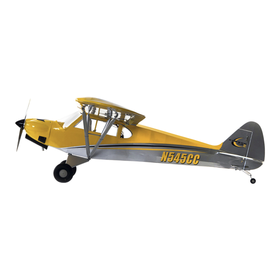
- Page 2 All manuals and user guides at all-guides.com SPECIFICATIONS • SPEZIFIKATIONEN • SPÉCIFICATIONS • SPECIFICHE LARGE PARTS LAYOUT • BAUTEILE (OHNE KLEINTEILE) • GRANDES PIÈCES • SCHEMA DEI COMPONENTI GRANDI 90 in (228 cm) 1170 sq in (75.5 dm2) Total/Totale 60 in (153 cm) 11.4 lb (5.2 kg) 2-Stroke Gas •...
- Page 3 All manuals and user guides at all-guides.com Part # English Deutsch Français Italiano REPLACEMENT PARTS • ERSATZTEILE • PIÈCES DE RECHANGE • PEZZI DI RICAMBIO 1 HAN506501 Fuselage Rumpf Fuselage Fusoliera HAN506502 Left Wing Linker Flügel Aile gauche Ala sinistra HAN506503 Right Wing Rechter Flügel...
- Page 4 All manuals and user guides at all-guides.com Part # English Deutsch Français Italiano REQUIRED RADIO EQUIPMENT • ERFORDERLICHE RC AUSRÜSTUNG • EQUIPEMENT RADIO REQUIS • APPARECCHIATURE RADIO AR7610 7-Channel DSMX Hi Speed SPMAR7610 AR7610 7-Kanal DSMX HiSpeed Empfänger Récepteur à grande vitesse DSMX 7 canaux AR7610 Ricevitore AR7610 7-canali DSMX Hi Speed Receiver ™...
- Page 5 All manuals and user guides at all-guides.com Part # English Deutsch Français Italiano REQUIRED ADHESIVES • ERFORDERLICHE KLEBSTOFFE • TYPES DE COLLES • ADESIVI NECESSARI PAAPT09 Thin CA Sekundenkleber dünnfl üssig Colle cyano fi ne Sottile CA PAAPT03 Medium CA Sekundenkleber mittel Colle cyano moyenne Medio CA...
- Page 6 Horizon Hobby, LLC. This manual contains instructions for safety, operation and maintenance. It is essential to read and follow all the instructions and warnings in the manual, prior to assembly, setup or use, in order to operate •...
- Page 7 Halten Sie lose Gegenstände die sich im Propeller verfangen können weg vom Propeller. Dieses gilt auch für Kleidung Alle Anweisungen, Garantien und anderen zugehörigen Dokumente können im eigenen Ermessen von Horizon Hobby, oder andere Objekte wie zum Beispiel Stifte oder Schraubendreher.
- Page 8 être utilisé par des enfants sans la surveillance directe d’un adulte. N’essayez pas de modifi er ou d’utiliser ce produit avec des composants incompatibles hors des instructions fournies par Horizon Hobby, LLC. Ce manuel comporte des Si l’entoilage présente quelque plis, vous pouvez les lisser en utilisant le pistolet à air chaud (HAN100) et le gant instructions relatives à...
- Page 9 • Se si trovano parti danneggiate, contattare il negozio da cui è stato acquistato. o alterare il prodotto in nessuna maniera al di fuori delle istruzioni fornite da Horizon Hobby, LLC. Questo manuale contiene le istruzioni per un funzionamento e una manutenzione sicuri. È fondamentale leggere e seguire tutte le Se si trovano delle pieghe nella ricopertura, si possono togliere usando una pistola ad aria calda (HAN100) e guanto per istruzioni e le avvertenze del manuale prima di montare, confi...
- Page 10 All manuals and user guides at all-guides.com HINGING THE AILERONS AND FLAPS Remove the aileron and fl ap from the wing panel. Place a Adjust the position of the fl ap and aileron so all gaps are T-pin in the center of each hinge. equal.
- Page 11 All manuals and user guides at all-guides.com AILERON SERVO INSTALLATION Remove the aileron and fl ap cover from the wing. Use a Place low-tack tape 1/32 inch (1 mm) from the control toothpick to puncture the covering to locate the holes for horn slot.
- Page 12 All manuals and user guides at all-guides.com Use a drill and a 1/16-inch (1.5mm) drill bit to drill the 11. Enlarge the outside hole in the aileron and fl ap servo holes for the servo mounting screws in the locations arms using a pin vise and 5/64-inch (2mm) drill bit.
- Page 13 All manuals and user guides at all-guides.com 16. Secure the aileron and fl ap covers in the wing using eight 21. Set the throw for the fl ap servo to 0% for both the up and M2 x 12 self-tapping screws for each servo cover. down positions at the transmitter.
- Page 14 All manuals and user guides at all-guides.com Slide the wing panel into position, guiding the extensions Check the alignment of the stabilizer to the wing. It from the wing into the fuselage. should be equal on both sides of the fuselage. Check that the wing fi...
- Page 15 All manuals and user guides at all-guides.com The elevator joiner wire must be fl ush with the leading 13. Slide the stabilizer partially into the fuselage so the edge of the elevator as shown. wood at the center is exposed. Mix 1/2 ounce (15ml) of 30-minute epoxy.
- Page 16 All manuals and user guides at all-guides.com 18. Fit the elevator so the leading edge fi ts tightly against the 23. Fit the elevators back into position. Remove the T-pins trailing edge of the stabilizer. and slide the elevators tightly against the stabilizer. Use a paper towel and isopropyl alcohol to remove any excess epoxy before it begins to cure.
- Page 17 All manuals and user guides at all-guides.com TAIL WHEEL BRACKET INSTALLATION 28. Flex the control surface through its range of motion a few Position the steering tiller on the bottom of the rudder. times to break-in the hinges. This will reduce the initial The arms of the tiller will be perpendicular to the rudder load on the servo when the surface is fi...
- Page 18 All manuals and user guides at all-guides.com Place the tail gear bracing bracket in the notch in the Attach the fi ttings to the fi n using an M3 x 12 screws and fuselage. Use two M3 x 20 socket head caps screws to M3 nut.
- Page 19 All manuals and user guides at all-guides.com Repeat steps 5 and 6, only passing the cable through the Install the rudder and elevator servos in the fuselage with fi ttings instead of the cable ends. The cables should have the servo outputs facing toward the front of the fuselage. very light tension.
- Page 20 All manuals and user guides at all-guides.com LANDING GEAR INSTALLATION 10. Thread an M2 nut on the pushrod, then a metal clevis. Attach the mount for the landing gear using an M3 With the servo centered, adjust the clevis so the elevator x 15 socket head cap screws and an M3 locknut.
- Page 21 All manuals and user guides at all-guides.com Attach the strut assembly to the main gear and the cross 11. Use four M3 nuts to secure the wheel hubs together. brace. Use the two M3 x 12 socket head cap screws at Make sure the wheel can rotate freely on the axle.
- Page 22 All manuals and user guides at all-guides.com Place hook and loop tape on the battery tray to keep the Thread the blind nuts included with the motor onto the screws with the prongs facing toward the wood. Apply battery from sliding inside the fuselage. The front of the battery tray is angled to match the thrust built into the threadlock to the screws and tighten them using a 2.5mm hex wrench.
- Page 23 All manuals and user guides at all-guides.com Insert the four M4 x 20 machine screws through the holes Secure the engine to the mounting rails. Use four M4 x 30 in the mount and into the holes drilled in the previous machine screws, eight M4 washers and four M4 locknuts.
- Page 24 All manuals and user guides at all-guides.com 13. Secure three 140mm pieces of fuel tubing to the tubes of 18. Carefully fi t the engine assembly into the fuselage. Guide the stopper. Note the position of each tube so they can be the leads through the fi...
- Page 25 All manuals and user guides at all-guides.com COWLING AND SPINNER INSTALLATION Cut four pieces of paper 1/2 inch (12mm) wide. Tape the Attach the muffl er to the engine and connect any items paper to the sides of the fuselage to indicate the location from the ignition module to their locations on the engine.
- Page 26 All manuals and user guides at all-guides.com Secure the remote receiver inside the fuselage using Use canopy glue to glue the side and rear windows to the hook and loop tape (not included). Make sure to orient the inside of the fuselage. Use tape to hold the windows in antenna on the remote receiver at a different angle than position until the glue has fully cured.
- Page 27 All manuals and user guides at all-guides.com WING STRUT INSTALLATION Before installing the strut brackets, thread an M3 x 12 Measure the distance between the end of the strut and socket head screw into each blind nut. If the screw does the jury strut mount.
- Page 28 All manuals and user guides at all-guides.com DECAL INSTALLATION 11. Position the wing back on the fuselage as outlined earlier Apply the decals to your model using the photos located in this section of the manual and the box art from your in this manual.
- Page 29 All manuals and user guides at all-guides.com CONTROL THROWS BUILDING NOTES: Turn on the transmitter and receiver of your model. Check the movement of the rudder using the transmitter. When the stick is moved to the right, the rudder should also move right. Reverse the direction of the servo at the transmitter if necessary.
- Page 30 INCIDENTAL OR CONSEQUENTIAL DAMAGES, LOSS OF your airplane. Use the recommended charger supplied Do not fl y below the manufacturer’s recommended Horizon Hobby, LLC, (Horizon) warrants to the original PROFITS OR PRODUCTION OR COMMERCIAL LOSS IN ANY with your radio system. Follow the instructions voltage.
- Page 31 Germany 25337 Elmshorn, When calling Horizon, you will be asked to provide your return freight. Horizon accepts money orders and Sales: Horizon Hobby GmbH +49 (0) 4121 2655 100 Germany complete name, street address, email address and phone cashier’s checks, as well as Visa, MasterCard, American number where you can be reached during business Express, and Discover cards.
- Page 32 All manuals and user guides at all-guides.com HÄNGEN VON QUERRUDERN UND KLAPPEN Querruder und Klappen von der Tragfl äche entfernen. Die Position von Klappe und Querruder ausrichten, sodass Einen T-Stift in die Mitte jeder Aufhängung platzieren. alle Zwischenräume gleich sind. Mit einem Feilkloben und einem 1,5 mm Bohrer ein Dünnen CA-Klebstoff auf die Ober- und Unterseite Loch in die Mitte der Schlitze jeder Aufhängung bohren,...
- Page 33 All manuals and user guides at all-guides.com MONTAGE DES SERVORS DES QUERRUDERS Abdeckung von Querruder und Klappen vom Flügel Klebeband mit geringer Klebekraft 1 mm vom Schlitz entfernen. Mit einem Zahnstocher die Abdeckung der Steuerfl äche platzieren. Damit wird verhindert, dass punktieren, um die Löcher für die Schrauben der Epoxid während der Klebung der Steuerhörner auf die Abdeckung von Querruder und Klappe zu lokalisieren.
- Page 34 All manuals and user guides at all-guides.com Mit einem 1,5 mm Bohrer Löcher für die Schrauben der 11. Das Außenloch in den Armen des Servos von Querruder Servohalterung an den im vorherigen Schritt markierten und Klappe mit einem Feilkloben und einem 2 mm Bohrer Stellen bohren.
- Page 35 All manuals and user guides at all-guides.com 16. Die Abdeckungen von Querruder und Klappe im Flügel mit 21. Den Ausschlag des Klappenservos auf 0 % für die acht M2 x 12 Blechschrauben für jede Servoabdeckung Auf- und Abwärtspositionen am Sender einrichten. Den sichern.
- Page 36 All manuals and user guides at all-guides.com Die Tragfl äche in Position schieben und die Die Ausrichtung des Stabilisators zum Flügel messen. Sie Verlängerungen vom Flügel in den Rumpf führen. sollte auf beiden Seiten des Rumpfs gleich sein. Prüfen, dass der Flügel fest gegen den Rumpf passt. Alle Ausrichtungen messen.
- Page 37 All manuals and user guides at all-guides.com Das Verbinderkabel des Höhenruders muss wie 13. Den Stabilisator teilweise in den Rumpf schieben, sodass abgebildet bündig mit der Vorderkante des Höhenruders das Holz in der Mitte freiliegt. 15 ml (1/2 oz) 30-minütigen abschließen.
- Page 38 All manuals and user guides at all-guides.com 18. Das Höhenruder einpassen, sodass die Vorderseite bündig 23. Die Höhenruder wieder in ihre ursprüngliche Position an die Rückseite des Stabilisators passt. einpassen. Die T-Stifte entfernen und die Höhenruder fest gegen den Stabilisator schieben. Mit einem Papiertuch und Isopropylalkohol überschüssiges Epoxid entfernen, ehe er auszuhärten beginnt.
- Page 39 All manuals and user guides at all-guides.com MONTAGE DER SPORNRADHALTERUNG 28. Die Steueroberfl äche einige Male durch ihren Die Steuerpinne auf die Unterseite des Seitenruders Bewegungsradius biegen, um die Aufhängungen positionieren. Die Arme der Pinne werden senkrechte zur einzuarbeiten. Dadurch wird die Anfangslast auf dem Mittellinie des Seitenruders stehen.
- Page 40 All manuals and user guides at all-guides.com Stützhalterung des Spornrad in die Kerbe des Rumpfs Die Fittings mit einer M3 x 12 Schraube und M3 Muttern platzieren. Mit zwei M3 x 20 Zylinderkopfschrauben am Seitenleitwerk befestigen. Die Fittings werden die Spornradhalterung sichern. Eine kleine Menge an beiden Seiten des Seitenruders platziert.
- Page 41 All manuals and user guides at all-guides.com Die Schritte 5 und 6 wiederholen, wobei das Kabel Die Servos von Seiten- und Höhenruder im Rumpf durch die Fittings anstatt den Kabelenden geführt wird. montieren, wobei die Servoausgänge Richtung der Die Kabel sollte eine sehr leichte Spannung aufzeigen. Vorderseite des Rumpfs weisen.
- Page 42 All manuals and user guides at all-guides.com MONTAGE DES FAHRWERKS 10. Eine M2 Mutter auf das Gestänge aufbringen, dann einen Die Halterung für das Fahrwerk mit einer M3 x 15 Metallgabelkopf. Bei zentriertem Servo den Gabelkopf Zylinderkopfschraube und einer M3 Kontermutter ausrichten, sodass das Höhenruder zentriert ist, wenn anbringen.
- Page 43 All manuals and user guides at all-guides.com Die Strebenbaugruppe an Hauptfahrwerk und Querstrebe 11. Mit vier M3 Muttern die Radnaben gemeinsam sichern. anbringen. Die zwei M3 x 12 Zylinderkopfschrauben Sicherstellen, dass das Rad frei auf der Achse drehen in der Mitte und die M3 x 15 Zylinderkopfschrauben in kann.
- Page 44 All manuals and user guides at all-guides.com Das Klettband auf die Akku-Halterung platzieren, um ein Die mit dem Motor mitgelieferten Blindmuttern auf die Schrauben aufbringen, wobei die Zacken auf das Verrutschen innerhalb des Rumpfs zu vermeiden. Die Vorderseite der Akku-Halterung ist angewinkelt, damit sie Holz gerichtet sind.
- Page 45 All manuals and user guides at all-guides.com Die vier M4 x 20 Maschinenschrauben durch die Löcher Den Motor zu die Schiene der Motorhalterung mit vier M4 in der Halterung und die im vorherigen Schritt gebohrten x 30 Maschinenschrauben, acht M4 Unterlegscheiben Löcher einfügen.
- Page 46 All manuals and user guides at all-guides.com 13. Drei 140 mm Stücke der Kraftstoffl eitung an den Rohren 18. Die Motorbaugruppe vorsichtig in den Rumpf einpassen. des Verschlusses sichern. Die Position jedes Rohrs Die Kabel durch das Brandschott führen und das beachten, sodass sie angeschlossen werden können, Zündmodul über dem Kraftstoffmotor halten.
- Page 47 All manuals and user guides at all-guides.com MONTAGE VON MOTORHAUBE UND SPINNER Vier Papierstücke mit einer Breite von 12 mm schneiden. Die Muffe am Motor anbringen und alle Teile vom Das Papier auf die Seiten des Rumpfs kleben, um die Zündmodul mit ihrer jeweiligen Position auf dem Motor Position des Brandschotts anzuzeigen.
- Page 48 All manuals and user guides at all-guides.com Funkempfänger innerhalb des Rumpfs mit Klettband Kanzelkleber verwenden, um die Seiten- und Rückfenster (nicht enthalten) sichern. Sicherstellen, die Antenne in die Innenseite des Rumpfs zu kleben. Mit Klebeband des Funkempfängers für den besten Betriebs des die Fenster in Position halten, bis der Kleber vollständig Funksystems in einem anderen Winkel als die des ausgehärtet ist.
- Page 49 All manuals and user guides at all-guides.com MONTAGE DER FLÜGELVERSTREBUNG Vor der Montage der Flügelverstrebung eine M3 x 12 Den Abstand zwischen dem Ende der Verstrebung und der Innensechskantschraube in jede Blindmutter schrauben. Halterung der Baldachinstreben messen. Die Halterungen Lässt sich die Schraube nur schwer schrauben, ein 3 mm sind auf der Verstrebung nicht zentriert: Die Seite, wo die Klebeband zum Reinigen des Gewindes in der Blindmutter Halterung 317 mm vom Ende der Verstrebung positioniert...
- Page 50 All manuals and user guides at all-guides.com MONTAGE DER DECALS 11. Die Flügel laut der Beschreibung in dieser Anleitung Die Decals auf dem Modell anhand der in diesem Abschnitt der Anleitung befi ndlichen Abbildungen und der wieder auf dem Rumpf positionieren. Die Enden auf Verpackungsgestaltung des Modells aufbringen.
- Page 51 All manuals and user guides at all-guides.com RUDERAUSSCHLAG MONTAGEHINWEISE: Den Sender und Empfänger des Modells einschalten. Die Bewegung des Seitenruders mit dem Empfänger prüfen. Wird der Hebel nach rechts bewegt, sollte sich auch das Seitenruder nach rechts bewegen. Die Richtung auf dem Servo am Empfänger bei Bedarf umkehren.
- Page 52 • Prüfen Sie den RC Einbau und stellen sicher dass alle vernünftig gesichert sind. Exklusive Garantie Horizon Hobby LLC (Horizon) Ausgeschlossen sind auch Fälle die bedingt durch (vii) Ruderfunktionen (Quer-, Höhen-, Seitenruder) und • Stellen Sie sicher, dass sich alle Ruder in die richtige...
- Page 53 Sie sich entweder an Ihren Fachhändler oder direkt an das Produkt repariert oder ersetzt. Diese Entscheidung Hinweise für die Wartung und den Betrieb des Produktes. Horizon. obliegt einzig Horizon Hobby. Es ist unabdingbar, diese Hinweise vor der ersten Rücksendungen / Reparaturen werden nur mit einer Kostenpfl ichtige Reparaturen Inbetriebnahme zu lesen und zu verstehen.
- Page 54 All manuals and user guides at all-guides.com MISE EN PLACE DES CHARNIERES DES AILERONS ET DES VOLETS Retirez l’aileron et le volet du panneau de l’aile. Placez Ajustez la position du volet et de l’aileron de manière à ce une épingle en T au centre de chaque charnière. que tous les espaces soient égaux.
- Page 55 All manuals and user guides at all-guides.com INSTALLATION DU SERVO DE L’AILERON Retirez le cache de l’aileron et du volet de l’aile. À l’aide Placez le ruban à faible adhérence à 1 mm de la fente du d’un cure-dent, percez le cache pour repérer les trous renvoi de commande.
- Page 56 All manuals and user guides at all-guides.com À l’aide d’une perceuse et d’une mèche de 1,5 mm, 11. À l’aide d’un porte-foret et d’une mèche de 2 mm, percez les trous des vis de fi xation du servo aux agrandissez le trou extérieur dans les bras de servo de emplacements marqués au cours de l’étape précédente.
- Page 57 All manuals and user guides at all-guides.com 16. Fixez les caches de l’aileron et du volet à l’aile en utilisant 21. Réglez l’inclinaison du servo de volet à 0 % pour huit vis à tôle M2 x 12 pour chaque cache du servo. les positions haut et bas du transmetteur.
- Page 58 All manuals and user guides at all-guides.com Glissez le panneau d’aile en position, en faisant passer Vérifi ez que le stabilisateur est bien aligné sur l’aile. les rallonges depuis l’aile dans le fuselage. L’alignement doit être le même des deux côtés du fuselage.
- Page 59 All manuals and user guides at all-guides.com La tige de profondeur doit être alignée avec le bord 13. Glissez partiellement le stabilisateur dans le fuselage d’attaque de profondeur comme dans l’illustration ci- pour exposer la partie centrale en bois. Préparez un contre.
- Page 60 All manuals and user guides at all-guides.com 18. Mettez la profondeur en place de sorte que le bord 23. Repositionnez les profondeurs. Retirez les épingles d’attaque soit bien installé sur le bord de fuite du en T et glissez les profondeurs fermement contre le stabilisateur.
- Page 61 All manuals and user guides at all-guides.com INSTALLATION DU SUPPORT DE ROUE DE QUEUE 28. Pliez plusieurs fois la surface de commande dans une Positionnez la barre de direction au bas du gouvernail. amplitude de mouvements pour rompre les charnières. Les bras de la barre seront perpendiculaires à...
- Page 62 All manuals and user guides at all-guides.com Placez le support de la roue de queue dans l’encoche du Fixez les raccords sur la dérive à l’aide d’une vis M3 x 12 fuselage. Utilisez les deux vis d’assemblage à six pans et d’un écrou M3.
- Page 63 All manuals and user guides at all-guides.com Répétez les étapes 5 et 6, en acheminant uniquement Installez les servos du gouvernail et de profondeur dans le câble dans les raccords à la place des extrémités le fuselage, les sorties du servo dirigées vers l’avant du câble.
- Page 64 All manuals and user guides at all-guides.com INSTALLATION DU TRAIN D’ATTERRISSAGE 10. Filetez un écrou M2 sur la barre de liaison, puis une Installez la fi xation du train d’atterrissage à l’aide manille métallique. Centrez le servo et ajustez la manille d’une vis d’assemblage à...
- Page 65 All manuals and user guides at all-guides.com Fixez le support au train d’atterrissage principal et à 11. Utilisez les 4 écrous M3 pour fi xer les moyeux. Veillez l’entretoise. Utilisez les 2 vis d’assemblage à six pans à ce que la roue pivote librement sur l’axe. Utilisez un creux M3 x 12 au centre, et les vis d’assemblage à...
- Page 66 All manuals and user guides at all-guides.com Placez la bande velcro sur le support de batterie pour Filetez les écrous borgnes fournis avec le moteur dans les vis en orientant les broches vers la surface boisée. éviter que celle-ci ne glisse dans le fuselage. L’avant du support de batterie est incliné...
- Page 67 All manuals and user guides at all-guides.com Introduisez les 4 vis mécaniques M4 x 20 dans les Fixez le moteur sur les rails de montage. Utilisez 4 vis trous du support et dans ceux percés lors de l’étape mécaniques M4 x 30, 8 rondelles M4, et 4 contre-écrous précédente.
- Page 68 All manuals and user guides at all-guides.com 13. Fixez 3 tubes pour carburant de 140 mm aux tubes du 18. Insérez avec précaution l’assemblage moteur dans bouchon. Notez la position de chaque tube de façon à le fuselage. Acheminez les fi ls dans le pare-feu et pouvoir les connecter lorsque le réservoir est installé...
- Page 69 All manuals and user guides at all-guides.com INSTALLATION DU CAPOT ET DU CONE Découpez 4 morceaux de papier d’une largeur de 12 mm. Fixez le silencieux au moteur et raccordez toutes les Collez le papier sur les côtés du fuselage pour indiquer pièces du module d’allumage à...
- Page 70 All manuals and user guides at all-guides.com Fixez le récepteur distant dans le fuselage à l’aide Utilisez de la colle pour verrières pour coller les fenêtres d’une bande velcro (non fournie). Pour assurer un latérale et arrière à l’intérieur du fuselage. Utilisez du fonctionnement optimal de votre système radio, veillez ruban adhésif pour maintenir les fenêtres jusqu’au à...
- Page 71 All manuals and user guides at all-guides.com INSTALLATION DES HAUBANS D’AILES Avant d’installer les haubans d’ailes, fi letez une vis à Mesurez la distance entre l’extrémité du hauban et le pans creux M3 x 12 dans chaque écrou borgne. Si la vis support de la contrefi...
- Page 72 All manuals and user guides at all-guides.com APPLICATION DES AUTOCOLLANTS 11. Repositionnez l’aile sur le fuselage selon les indications Appliquez les autocollants sur votre maquette en vous aidant des illustrations de cette section du manuel et de la contenues plus haut dans ce manuel. Ajustez les boîte de votre maquette.
- Page 73 All manuals and user guides at all-guides.com COUDES DE COMMANDE NOTES RELATIVES AU MONTAGE: Mettez l’émetteur et le récepteur de votre maquette sous tension. Vérifi ez le mouvement du gouvernail à l’aide de l’émetteur. Lorsque le manche se déplace vers la droite, le gouvernail doit également se déplacer vers la droite. Inversez le sens du servo au niveau de l’émetteur le cas échéant.
- Page 74 Utilisez le chargeur fourni avec votre Ne volez jamais en dessous de la tension minimale Garantie exclusive - Horizon Hobby, LLC (Horizon) garantit de revenus ou de pertes commerciales, liés de quelque radio. Suivez les instructions fournies avec votre recommandée par le fabricant.
- Page 75 Cette coûteuses et doivent par conséquent être effectuées revendeur qui conviendra avec Horizon d’une décision décision relève uniquement d’Horizon Hobby. par l’acheteur lui-même. appropriée, destinée à vous aider le plus rapidement Réparations payantes...
- Page 76 All manuals and user guides at all-guides.com METTERE LE CERNIERE AD ALETTONI E FLAP Staccare alettoni e fl ap dal pannello alare. Mettere uno Regolare la posizione di alettoni e fl ap in modo che tutte spillo a T al centro di ogni cerniera. le fenditure siano uguali.
- Page 77 All manuals and user guides at all-guides.com INSTALLAZIONE DEL SERVO ALETTONI Togliere i coperchi dalle sedi per i servi di alettoni e Mettere del nastro a bassa adesività alla distanza di fl ap. Con uno stuzzicadenti forare il rivestimento per 1mm dalla sede della squadretta.
- Page 78 All manuals and user guides at all-guides.com Con una punta da 1,5mm praticare i fori per le viti di 11. Con una punta da 2mm allargare il foro più esterno sulle fi ssaggio del servo nei punti segnati prima. squadrette dei servi di fl ap e alettoni. Con una chiavetta esagonale da 2mm avvitare una vite 12.
- Page 79 All manuals and user guides at all-guides.com 16. Fissare i coperchi dei servi di alettoni e fl ap con otto viti 21. Dal trasmettitore regolare la corsa per il servo dei fl ap a autofi lettanti M2x12 per ciascuno. 0% sia in su che in giù. Mettere l’interruttore di comando nella posizione centrale.
- Page 80 All manuals and user guides at all-guides.com Posizionare l’ala guidando le prolunghe nella fusoliera. Controllare l’allineamento dello stabilizzatore all’ala. Deve essere uguale su entrambi i lati della fusoliera. Verifi care che l’ala si adatti perfettamente alla fusoliera. Controllare tutti gli allineamenti, segnando sopra e sotto lo stabilizzatore il bordo della fusoliera.
- Page 81 All manuals and user guides at all-guides.com Il fi lo di acciaio che unisce i due semi elevatori deve 13. Inserire parzialmente lo stabilizzatore nella fusoliera essere a fi lo del loro bordo di entrata, come illustrato. in modo che il legno al centro sia in vista. Miscelare 15ml di colla epoxy 30 minuti e applicarla, con apposito pennello, sul legno della parte centrale superiore dello stabilizzatore.
- Page 82 All manuals and user guides at all-guides.com 18. Sistemare l’elevatore in modo che il suo bordo di entrata 23. Rimontare gli elevatori. Togliere gli spilli a T e inserire gli sia perfettamente adattato al bordo di uscita dello elevatori ben contro allo stabilizzatore. Con un fazzoletto stabilizzatore.
- Page 83 All manuals and user guides at all-guides.com INSTALLAZIONE DEL SUPPORTO PER IL RUOTINO DI CODA 28. Flettere le superfi ci mobili per tutta la loro escursione Posizionare la squadretta sulla parte inferiore del timone. alcune volte per fare un po’ di rodaggio alle cerniere. I bracci della squadretta devono essere perpendicolari Questo per ridurre il carico iniziale sui servi.
- Page 84 All manuals and user guides at all-guides.com Sistemare la staffa di rinforzo del supporto per il carrello Fissare gli attacchi alla deriva con viti da M3x12 e relativo di coda nella sua tacca ricavata sulla fusoliera. Fissare dado M3. Gli attacchi vengono fi ssati su entrambi i lati del il supporto con due viti a brugola M3x20.
- Page 85 All manuals and user guides at all-guides.com Ripetere i passi 5 e 6 facendo passare il cavo solo negli Installare in fusoliera i servi per il timone e l’elevatore attacchi invece che nei terminali. I cavi dovrebbero con gli alberi di uscita rivolti verso la parte anteriore avere una leggera tensione.
- Page 86 All manuals and user guides at all-guides.com INSTALLAZIONE DEL CARRELLO 10. Avvitare un dado M2 sul rinvio e poi una forcella Fissare il supporto per il carrello con viti a brugola metallica. Con il servo centrato, regolare la forcella da M3x15 e relativo dado autobloccante da M3, in modo che l’elevatore sia centrato quando essa è...
- Page 87 All manuals and user guides at all-guides.com Fissare il gruppo sospensioni al carrello principale e ai 11. Bloccare il mozzo con quattro dadi M3, accertandosi che bracci incrociati. Al centro usare due viti a brugola da la ruota possa girare liberamente. Stringere le viti con M3x12 e M3x15 vicino alle ruote.
- Page 88 All manuals and user guides at all-guides.com Mettere del nastro a strappo sul supporto batteria per Avvitare sulle viti i dadi ciechi forniti con il motore con i rebbi rivolti verso il legno. Applicare del frenafi letti sulle evitare che la batteria scorra all’interno della fusoliera. La parte anteriore del supporto batteria è...
- Page 89 All manuals and user guides at all-guides.com Inserire quattro viti M4x20 nel supporto motore e nei fori Fissare il motore al suo supporto con quattro viti M4x30, appena fatti. otto rondelle M4 e quattro dadi autobloccanti M4. Mettere sulle viti le quattro rondelle M4 e poi avvitare i Con una punta da 4mm praticare i fori per il rinvio dadi autobloccanti M4.
- Page 90 All manuals and user guides at all-guides.com 13. Fissare ai tubetti del tappo tre pezzi di tubo per 18. Inserire con attenzione il gruppo motore nella fusoliera. carburante lunghi 140mm. Notare la posizione di ciascun Far scorrere i cavi attraverso l’ordinata parafi amma e tubo per poterli poi collegare quando il serbatoio sarà...
- Page 91 All manuals and user guides at all-guides.com INSTALLAZIONE DELLA CAPOTTINA MOTORE E DELL’OGIVA Tagliare quattro pezzi di carta larghi 12mm e fi ssarli sulla Fissare il silenziatore al motore e collegare al motore tutti fusoliera con nastro adesivo per indicare la posizione i cavi provenienti dal modulo dell’accensione.
- Page 92 All manuals and user guides at all-guides.com Fissare in fusoliera la ricevente remota usando del nastro Incollare le fi nestre laterali e posteriori all’interno della a strappo (non fornito). Per ottenere il miglior rendimento, fusoliera usando colla per capottine. Tenere ferme le accertarsi che l’antenna della ricevente remota abbia un fi...
- Page 93 All manuals and user guides at all-guides.com INSTALLAZIONE DEI MONTANTI ALARI Prima di installare le staffe di fi ssaggio dei montanti, Misurare la distanza tra il terminale del montante e avvitare una vite a brugola da M3x12 in ogni dado cieco. il nottolino nell’ala.
- Page 94 All manuals and user guides at all-guides.com APPLICAZIONE DELLE DECALS 11. Rimettere le ali sulla fusoliera come indicato prima Applicare le decals sul modello usando le foto che si trovano in questa sezione del manuale e sulla scatola del in questo manuale e regolare i terminali dei montanti modello.
- Page 95 All manuals and user guides at all-guides.com CORSE DEI COMANDI NOTE PER LA COSTRUZIONE: Accendere la trasmittente e la ricevente del modello. Controllare il movimento del timone con il radiocomando. Quando si sposta lo stick a destra il timone si deve spostare verso destra. Se necessario intervenire sul Reverse del tramettitore.
- Page 96 Non volare se la tensione è inferiore a quella indicata Garanzia esclusiva - Horizon Hobby, LLC (Horizon) non idonei a cura di soggetti diversi da Horizon. La consigliati o forniti con il radiocomando e seguendo dal costruttore;...
- Page 97 Horizon per prendere una decisione che vi Questa decisione spetta esclusivamente a Horizon Hobby. possa aiutare nel più breve tempo possibile. Riparazioni a pagamento Manutenzione e riparazione...
- Page 98 All manuals and user guides at all-guides.com...
- Page 99 All manuals and user guides at all-guides.com Carbon Cub 15cc...
- Page 100 All manuals and user guides at all-guides.com © 2016 Horizon Hobby, LLC. Hangar 9, DSMX, EC3 and the Horizon Hobby logo are trademarks or registered trademarks of Horizon Hobby, LLC. The Spektrum trademark is used with permission of Bachmann Industries, Inc.