Napoleon B42NTRE Manuel D'installation Et D'utilisation
Masquer les pouces
Voir aussi pour B42NTRE:
- Instructions d'installation et d'opération (144 pages) ,
- Instructions d'installation et d'utilisation (132 pages)
Publicité
Les langues disponibles
Les langues disponibles
Liens rapides
NATURAL GAS MODELS:
PROPANE GAS MODELS:
SAFETY INFORMATION
WARNING
!
FIRE OR EXPLOSION HAZARD
Failure to follow safety warnings exactly
could result in serious injury, death, or
property damage.
- Do not store or use gasoline or other
fl ammable vapors and liquids in the vicinity of
this or any other appliance.
- WHAT TO DO IF YOU SMELL GAS:
•
Do not try to light any appliance.
•
Do not touch any electrical switch; do not
use any phone in your building.
•
Immediately call your gas supplier from a
neighbour's phone. Follow the gas
supplier's instructions.
•
If you cannot reach your gas supplier, call
the fi re department.
- Installation and service must be
performed by a qualifi ed installer, service
agency, or the supplier.
This appliance may be installed in an aftermarket,
permanently located, manufactured home (USA
only) or mobile home, where not prohibited by
local codes.
This appliance is only for use with the type of gas
indicated on the rating plate. This appliance is
not convertible for use with other gases, unless
a certifi ed kit is used.
INSTALLER:
Leave this manual with the appliance
CONSUMER:
Retain this manual for future reference
Wolf Steel Ltd., 24 Napoleon Rd., Barrie, ON, L4M 0G8 Canada / 103 Miller Drive, Crittenden, Kentucky, USA, 41030
$10.00
B42NTR / B42NTRE
ADD PRODUCT CODE HERE (TRADE GOTHIC LT STD FONT)
B42PTR / B42PTRE
Phone 1 (866) 820-8686 • www.napoleon.com • hearth@napoleon.com
INSTALLATION AND
ADD MANUAL TITLE
OPERATION MANUAL
CERTIFIED TO THE CANADIAN AND AMERICAN NATIONAL STANDARDS:
CSA 2.22 AND ANSI Z21.50 FOR VENTED DECORATIVE GAS APPLIANCES
IF INSTALLATION + OPERATION, ADD SERIAL
CSA /
INTERTEK
BARCODE LABEL ON THE OWNER'S MANUAL"
LOGO
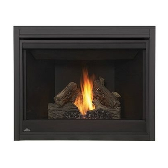
Ascent™ 42
Product Name / Code
(MUST use title from Price Book)
ADD ____ ILLUSTRATED
ADD PRODUCT IMAGE
FOR INDOOR USE ONLY
NUMBER LABEL HERE
IF SEPARATE MANUALS, ADD "PLACE
ENGLISH
FRENCH PG. 75
W415-2367 / B / 12.09.20
Publicité

Manuels Connexes pour Napoleon B42NTRE


Sommaire des Matières pour Napoleon B42NTRE
- Page 1 INTERTEK BARCODE LABEL ON THE OWNER’S MANUAL” LOGO Wolf Steel Ltd., 24 Napoleon Rd., Barrie, ON, L4M 0G8 Canada / 103 Miller Drive, Crittenden, Kentucky, USA, 41030 Phone 1 (866) 820-8686 • www.napoleon.com • hearth@napoleon.com $10.00 W415-2367 / B / 12.09.20...
- Page 2 safety information WARNING DANGER • This appliance is hot when operated and can cause severe burns if contacted. • Any changes or alterations to this appliance or its controls can be dangerous and is prohibited. HOT GLASS WILL CAUSE • Do not operate appliance before reading and BURNS.
- Page 3 patterns. RAAK HET GLAS NIET AAN TOT HET IS AFGEKOELD. DUTCH safety information LAAT KINDEREN NOOIT HET GLAS AANRAKEN. WARNING Dit apparaat is voorzien van een barrière die is ontworpen om het risico van brandwonden door het hete kijkglas te beperken. Deze barrière moet worden geïnstalleerd ter bescherming van kinderen •...
- Page 4 table of contents general information gas installation rates and efficiencies operation (electronic) installation overview pilot on demand rating plate information operation (millivolt) mobile home installation finish framing dimensions minimum framing dimensions venting requirements 10.0 finishing typical vent installation 10.1 safety barrier / door removal and special vent installations installation 2.2.1 periscope termination...
- Page 5 Natural Gas: B42NTR Propane: B42PTR B42NTRE B42PTRE 1.0 general information When the appliance is installed at elevations above 4,500 ft (1371m), and in the absence of specific recommendations from the local authority having jurisdiction, the certified high altitude input rating shall be reduced at the rate of 4% for each additional 1,000 ft (305m).
- Page 6 general information installation overview Recommended installation steps: 1. Determine venting requirements before deciding the final location of the appliance. 2. Install rough framing (see “rough framing” section). 3. Place the appliance in its final position. 4. Install appliance venting (see “venting installation” section). 5.
- Page 7 general information WARNING • Always light the pilot - whether for the first time or if the gas supply has run out - with the glass door opened or removed. • Provide adequate clearance for servicing and operating the appliance. •...
- Page 8 Recessed depth X” Profondeur d’encastré une face X” L’appareil doit être ventilé à l’aide de l’ensemble d’évacuation propre à Napoleon. Référez au *** Mantel X” from appliance opening *** Tablette X” de l’ouverture de l’appareil manuel d’installation pour les spécifications d’évacuation. Il est nécessaire de bien réinstaller et *** Maximum horizontal extension: *** L’extension horizontale maximale: X”.
- Page 9 general information dimensions W415-2367 / B / 12.09.20...
- Page 10 2.0 venting requirements WARNING • Risk of fi re. Maintain specifi ed air space clearances to vent pipe and appliance. • The vent system must be supported every 3’(0.9m) for both vertical and horizontal runs. Use support ring assembly W010- 0067 or equivalent non-combustible strapping to maintain the minimum clearance to combustibles for both vertical and horizontal runs.
- Page 11 The air terminal must remain unobstructed at all times. Examine the air terminal at least once a year to verify that it is unobstructed and undamaged. Rigid and fl exible venting systems must not be combined. Different venting manufacturer components must not venting requirements be combined.
- Page 12 venting requirements 16" (40.6cm) minimum 40 ft (12m) maximum 3 ft (1m) minimum 20" (50.8cm) maximum 24 1/8" (61.3cm) 24 1/8" minimum plus (61.3cm) rise* REAR VENT * See "venting" section W415-2367 / B / 12.09.20...
- Page 13 venting requirements special vent installations 2.2.1 periscope termination Use the periscope kit to locate the air termination above grade. The periscope must be installed so that when fi nal grading is completed, the bottom air slot is located a minimum 12” (305mm) above grade. The maximum allowable vent length (including both rise and run) is 10’...
- Page 14 venting requirements minimum air terminal location clearances Covered balcony applications ††* = 3 feet ≤ 15 feet = 2 x ACTUAL (0.9m) (4.6m) note: INSTALLATIONS Wall terminals are for illustration purposes only. Size and shapes may vary. CANADA U.S.A. 12” (30.5cm) 12”...
- Page 15 venting requirements venting application flow chart TOP EXIT Horizontal Termination Vertical Termination Vertical rise is equal Vertical rise is equal Vertical rise is less Vertical rise is less to or greater than to or greater than than horizontal run than horizontal run the horizontal run the horizontal run Horizontal run +...
- Page 16 venting requirements elbow vent length values Feet Inches Millimeters 1° 0.03 12.7 15° 0.45 152.4 30° 11.0 279.4 45° 1.35 16.0 406.4 90°* 32.0 812.8 * The fi rst 90° offset has a zero value and is shown in the formula as - 90° * The fi rst 45°...
- Page 17 venting requirements ) > (V Simple venting configuration See graph to determine the required vertical rise V for the required horizontal run H (only one 90° elbow) 150 (381) 147 (373) REQUIRED VERTICAL 100 (254) RISE IN INCHES (CENTIMETERS) V 57 (145) 50 (127) 8 (20.3)
- Page 18 venting requirements rear exit horizontal termination ) < (V See graph to determine the required vertical rise V for the required Simple venting configuration horizontal run H (only two 90° elbows) 40 (12.2) 38.3 (11.7) REQUIRED 30 (9.1) VERTICAL RISE IN FEET 20 (6.1) (METERS) V 10 (3.1)
- Page 19 venting requirements ) > (V Simple venting configuration See graph to determine the required vertical rise V for the (only two 90° elbows) required horizontal run H 150(3810) 150(3810) 147 (3733.8 147 (3733.8 Simple venting configuration REQUIRED (only one 90° elbow) VERTICAL RISE IN 100 (2540) 100 (2540)
- Page 20 venting requirements top and rear exit vertical termination ) < (V See graph to determine the required vertical rise V for the Simple venting configurations. required horizontal run H 40 (12.2) 30 (9.1) REQUIRED VERTICAL RISE IN FEET (METERS)V 20 (6.1) 10 (3.1) 3 (0.9) 5 (1.5)
- Page 21 venting requirements ) > (V Simple venting configurations. See graph to determine the required vertical rise V for the required horizontal run H 20 (6.1) 19 (5.8) REQUIRED VERTICAL RISE IN FEET 10 (3.1) (METERS)V 3 (0.9) (1.5) (3.1) (4.6) (6.1) (7.6) (9.1)
- Page 22 3.11 rear exit venting requirements WARNING 2.10 rear exit FAILURE TO CREATE A SEAL TO THE FIREBOX WITH THE EXHAUST COLLAR ASSEMBLY WILL CAUSE WARNING THE APPLIANCE TO FUNCTION IMPROPERLY AND CAN CAUSE INJURY OR PROPERTY DAMAGE. Fig. 1 • Failure to create a seal to the firebox with the exhaust collar assembly will cause the appliance to function improperly and can cause injury or property damage.
- Page 23 venting requirements 2.12 top exit WARNING • Failure to install the cover plate and gasket will cause the appliance to function improperly and can cause injury or property damage. This appliance is factory shipped as a rear vent model equipped with a #44 burner orifice. This orifice size is suitable for rear vent installations with 0"...
- Page 24 3.0 rough framing note: When using optional fi nishing accessories, the framing dimensions and fi nishing materials may differ from what is outlined in the section below; refer to the leafl et instructions supplied in the accessory kit for specifi c framing and fi nishing specifi cations.
- Page 25 rough framing minimum framing dimensions HORIZONTAL VENT SECTIONS: A minimum of 1" (25mm) at the bottom and sides and 3" (76mm) at the top of the vent pipe on all horizontal runs to combustibles is required. note: The minimum clearances from the top of the horizontal vent pipe to combustible materials may be reduced from 3"...
- Page 26 rough framing minimum enclosure clearances TOP VENT 34 5/8" (87.9cm) TOP EXIT ENCLOSURE The appliance requires a minimum enclosure height of 50 1/2" (128.3cm). For temperature requirements, the enclosure space around and above the appliance must be left unobstructed. * See "minimum framing dimension" section for details on reducing vent pipe top clearances. These parameters also apply to the illustrations found in the "minimum enclosure clearances"...
- Page 27 rough framing MINIMUM REAR VENT CLEARANCES For rear vent termination not exceeding 10" (254mm) of horizontal vent run. REAR EXIT ENCLOSURE The appliance requires a minimum enclosure height of 41 5/8" (105.7cm). For temperature requirements, the enclosure space around and above the appliance must be left unobstructed. * See "venting"...
- Page 28 rough framing MAXIMUM REAR VENT CLEARANCES (EXAMPLE 1) For rear vent termination exceeding 10" (254mm). REAR EXIT ENCLOSURE The appliance requires a minimum enclosure height of 41 5/8" (105.7cm). For temperature requirements, the enclosure space around and above the appliance must be left unobstructed. * See "venting"...
- Page 29 rough framing MAXIMUM REAR VENT CLEARANCES (EXAMPLE 2) REAR EXIT ENCLOSURE The appliance requires a minimum enclosure height of 41 5/8" (105.7cm). For temperature requirements, the enclosure space around and above the appliance must be left unobstructed. * See "venting" section. W415-2367 / B / 12.09.20...
- Page 30 rough framing note: For heavier finishing materials such as marble, we recommend adding extra support to the frame. Ensure there is adequate floor support for the appliance and finishing material. Before framing your appliance, determine vent requirements before deciding the final location of the appliance. After rough framing, place the appliance in its final position.
- Page 31 4.0 venting installation WARNING • Ensure to unpack all loose materials from inside the fi rebox prior to connecting the gas and electrical supply • If your appliance is supplied with a remote, ensure the remote receiver is in the “OFF” position prior to connecting the gas and electrical supply to the appliance.
- Page 32 venting installation horizontal installation WARNING • The fi restop assembly must be installed with the vent shield to the top. • Terminals must not be recessed into a wall or siding more than the depth of the return fl ange of the mounting plate.
- Page 33 venting installation vertical installation This application occurs when venting through a roof. Installation kits for various roof pitches are available from your authorized dealer / distributor. See the “accessories” section to order specifi c kits required. A. Determine the air terminal location, cut and frame a square opening, as illustrated, in the ceiling and the roof to provide the minimum 1"...
- Page 34 venting installation using either flexible vent components WARNING • Do not allow the inner fl ex pipe to bunch up on horizontal or vertical runs and elbows. Keep it pulled tight. • Spacers are attached to the inner fl ex pipe at predetermined intervals to maintain an even air gap to the outer fl ex pipe.
- Page 35 venting installation 4.3.2 vertical air terminal installation WARNING • Maintain a minimum 2” (51mm) space between the air inlet base and the storm collar. note: Fastening hardware provided with appropriate roof terminal and liner kits. Fasten the roof support to the roof using 6 screws. The roof support is optional.
- Page 36 venting installation 4.3.4 horizontal air terminal installation WARNING • Risk of fire! Do not allow loose materials or insulation to touch the vent pipe. Remove insulation to allow for the installation of the attic shield and to maintain clearances to combustibles. Move the appliance into position.
- Page 37 venting installation 4.3.5 vertical air terminal installation WARNING • Maintain a minimum 2” (51mm) space between the air inlet base and the storm collar. note: Fastening hardware provided with appropriate roof terminal and liner kits. Before attaching elbows to the collars on the back of the appliance, 1 1/2” (38.1mm) will need to be trimmed off the 4”...
- Page 38 venting installation vertical through existing chimney WARNING • Risk of fi re. • Co-axial to co-linear venting confi gurations must only be used in a non-combustible chimney or enclosure. Installation in a combustible enclosure could result in a fi re. This appliance is designed to be attached to a 3”...
- Page 39 venting installation 4.4.1 restricting vertical vents WARNING • Turn off gas and electrical supply before servicing the appliance. • Appliance may be hot. Do not service until appliance is cool. • For safe and proper operation of the appliance, follow the venting instructions exactly. •...
- Page 40 5.0 electrical information electronic wiring diagram WARNING • Do not wire 110 volts to the valve or wall switch. (where applicable) GREEN ON / OFF ORANGE SWITCH TRANSFORMER IPI / CPI ON / OFF BATTERY HOUSING ELECTRONIC DISCONNECT THESE VALVE CONNECTIONS TO THE ON/OFF SWITCH.
- Page 41 electrical information battery back-up installation WARNING • Ensure the gas and electrical power to the appliance is turned off. • Appliance may be hot. Do not service until the appliance has cooled. note: In the event of a power failure, your appliance can be operated using the battery back-up supplied. Before beginning installation, disconnect the gas and electrical power supply from the appliance.
- Page 42 electrical information optional wall switch WARNING • Do not connect either the wall switch, thermostat or gas valve directly to 110 volt electricity. For ease of accessibility, an optional remote wall switch or millivolt thermostat may be installed in a convenient SIT MILLIVOLT location.
- Page 43 6.0 gas installation WARNING • Risk of fi re, explosion, or asphyxiation. Ensure there are no ignition sources such as sparks or open fl ames. • Support gas control when attaching gas supply pipe to prevent damaging gas line. • Always light the pilot whether for the fi rst time or if the gas supply has run out with the glass door opened or removed.
- Page 44 7.0 operation (electronic) WARNING • If you do not follow these instructions exactly, a fi re or explosion may result causing property damage, personal injury, or loss of life. • If applicable, always light the pilot whether for the fi rst time or if the gas supply has run out with the glass door opened or removed.
- Page 45 In order to start your pilot, turning the main burner on with the switch, remote or thermostat and then turning it off will reactivate the continuous pilot mode and reset the seven day timer. For further information, refer to www.napoleon.com/pilotondemand. 31.2A...
- Page 46 8.0 operation (millivolt) WARNING • If you do not follow these instructions exactly, a fi re or explosion may result causing property damage, personal injury, or loss of life. • If applicable, always light the pilot whether for the fi rst time or if the gas supply has run out with the glass door opened or removed.
- Page 47 9.0 finish framing minimum framing dimensions 35" 88.9cm 2 3/16" (56mm) 7 3/16" (182mm) 18 9/16" 47.2cm W415-2367 / B / 12.09.20...
- Page 48 10.0 finishing WARNING • Risk of fire! • Never obstruct the front opening of the appliance. • The front of the appliance must be finished with any non-combustible materials such as brick, marble, granite, etc., provided that these materials do not go below the specified dimension, as illustrated. •...
- Page 49 finishing 10.2 front hood installation note: This hood must be installed, if it has not already been factory installed. Remove safety door and barrier. Remove the securing screws from the top of the firebox, as shown. Install the front hood, ensuring it is angled downward when installed. Reinstall the previously removed securing screws.
- Page 50 finishing 10.3 non-combustible facing material WARNING Non-combustible facing material must not project more than 4” (101.6mm) from the face of the door (all four sides). If greater projections are desired, increase the clearance to the sides, bottom and top by 2” (50.8mm) for every additional 1”...
- Page 51 finishing 10.4 minimum mantel clearances WARNING • Risk of fi re. Maintain all specifi ed air space clearances to combustibles. Failure to comply with these instructions may cause a fi re or cause the appliance to overheat. Ensure all clearances (i.e. back, side, top, vent, mantel, front, etc.) are clearly maintained.
- Page 52 finishing 10.5 recessed installation WARNING • Installing a television or other electronics above the appliance may cause discolouration, melting, or damage to the electronics. Use clearances as guidelines and refer to your manufacturer's instructions for further information. MINIMUM CLEARANCES CHART 6"...
- Page 53 finishing 10.6 nailing tab installation Nailing tabs are provided as part of the frames, as shown. To determine the final location and where to bend the nailing tabs you must first determine the thickness of your finishing material (i.e. IMAGE drywall).
- Page 54 The logs are fragile and should be handled with care. PHAZER logs and glowing embers, exclusive to Napoleon, provide a unique and realistic glowing effect that is different in every installation. Take the time to carefully position the glowing embers for a maximum glowing effect. Log 48.1...
- Page 55 finishing Place log #5 (W135-0687) onto D1 located in front Place log #4 (W135-0688) on the front left of log #2. side of the support tray. Do not cover any burner ports. notches Rest the other end of log #6 in the notch of log #2.
- Page 56 finishing 10.8 glowing embers WARNING • Completely blocking the burner ports can cause an incorrect fl ame pattern, carbon deposits and delayed ignition. Tear the embers into pieces and loosely layer above the burner ports covering the burner area. Care should be taken to shred the embers into thin, small irregular pieces as only the exposed edges of the fi bre hairs will glow.
- Page 57 NOTE: fOr mOrE dETailEd iNsTrucTiONs rEfEr TO yOur iNsTallaTiON maNual. NOTE: fOr mOrE dETailEd iNsTrucTiONs rEfEr TO yOur iNsTallaTiON maNual. W415-1479 / A / 05.09.16 W415-1479 / A / 05.09.16 Wolf Steel Ltd., 24 Napoleon Rd., Barrie, ON L4M 0G8 Canada • (705)721-1212 • fax (705)720-9081 • www.napoleonfireplaces.com Wolf Steel Ltd., 24 Napoleon Rd., Barrie, ON L4M 0G8 Canada...
- Page 58 12.0 adjustment 12.1 pilot burner adjustment Adjust the pilot screw to provide properly sized fl ame. Turn in a clockwise direction to reduce the gas fl ow. Check Pressure Readings: PILOT 3/8” - 1/2” ELECTRODE Inlet pressure can be checked by turning screw (A) counter- BURNER ELECTRONIC (9.5mm - 12.7mm)
- Page 59 Flame must envelop La flamm upper adjustments la therm 3/8" to 1/2" 12.2 venturi adjustment (12.7mm - 9.5mm) of (9.5 thermocouple This appliance has an air shutter that has been factory set open according to the chart below: VENTURI Regardless of venturi orientation, closing the air shutter will cause a more BURNER yellow flame, but can lead to carbonization.
- Page 60 13.0 maintenance WARNING • Turn off the gas and electrical power before servicing the appliance. • Appliance may be hot. Do not service until appliance has cooled. • Do not use abrasive cleaners on glass. • Do not paint the pilot assembly. This appliance and its venting system should be inspected before use and at least annually by a qualifi ed service person.
- Page 61 • Using a vacuum with soft brush attachment, gently remove any dirt, debris, or carbon build up from the logs, fi rebox, and burner. For glass media, follow the installation instructions for pre-cleaning. • Gently remove any build-up on the pilot assembly including thermopile, thermocouple, fl ame sensor, and maintenance igniter (if equipped).
- Page 62 14.0 replacement parts WARNING • Failure to position the parts in accordance with this manual or failure to use only parts specifi cally approved with this appliance may result in property damage or personal injury. Contact your dealer for questions concerning prices and policies on replacement parts. Normally, all parts can be ordered through your Authorized dealer / distributor.
- Page 63 replacement parts W415-2367 / B / 12.09.20...
- Page 64 replacement parts W415-2367 / B / 12.09.20...
- Page 65 replacement parts W415-2367 / B / 12.09.20...
- Page 66 15.0 accessories W415-2367 / B / 12.09.20...
- Page 67 16.0 troubleshooting (electronic) WARNING • Always light the pilot whether for the fi rst time or if the gas supply has run out, with the glass door open or removed. • Turn off gas and electrical power before servicing the appliance. •...
- Page 68 Check that venting is installed correctly. appliances). Room is in negative pressure; increase fresh air supply. troubleshooting (electronic) symptom problem test solution Pilot will not light. Makes Wiring: short, loose, or damaged Verify the thermocouple/sensor is clean and the wiring is undamaged. Verify the interrupter block is not damaged or too tight.
- Page 69 Wire connector pins are bent. Straighten pins. Valve wiring is damaged. Replace valve. troubleshooting (electronic) symptom problem test solution Lights or blower Control module switch in Verify ON/OFF switch is in the “I” position which denotes on. won’t function (if wrong position.
- Page 70 17.0 troubleshooting (millivolt) WARNING • Always light the pilot whether for the fi rst time or if the gas supply has run out, with the glass door open or removed. • Turn off gas and electrical power before servicing the appliance. •...
- Page 71 troubleshooting (millivolt) symptom problem test solution Pilot will not light. No spark at pilot burner. Check if pilot can be lit by a match. Check that the wire is connected to the push button ignitor. Check if the push button ignitor needs tightening. Replace the wire if the wire insulation is broken or frayed.
- Page 72 Napoleon neither assumes, nor authorizes any third party to assume, on its behalf, any other liabilities with respect to the sale of this product. Napoleon will not be responsible for: over- fi ring, downdrafts, spillage caused by environmental conditions such as rooftops, buildings, nearby trees, hills, mountains, inadequate vents or ventilation, excessive venting confi gurations, insuffi cient makeup air, or negative air pressures which may or may not be caused by mechanical systems such as exhaust fans, furnaces, clothes dryers, etc.
- Page 73 notes 29.1 W415-2367 / B / 12.09.20...
- Page 74 NAPOLEON CELEBRATING OVER 40 YEARS OF HOME COMFORT PRODUCTS 7200, Route Transcanadienne, Montréal, Québec H4T 1A3 24 Napoleon Road, Barrie, Ontario, Canada L4M 0G8 214 Bayview Drive, Barrie, Ontario, Canada L4N 4Y8 103 Miller Drive, Crittenden, Kentucky, USA 41030 De Riemsdijk 22, 4004 LC Tiel, The Netherlands Phone: 1-866-820-8686 napoleon.com...
- Page 75 IF SEPARATE MANUALS, ADD “PLACE LOGO BARCODE LABEL ON THE OWNER’S MANUAL” Wolf Steel Ltd., 24 Napoleon Rd., Barrie, ON, L4M 0G8 Canada / 103 Miller Drive, Crittenden, Kentucky, USA, 41030 Téléphone 1(866)820-8686 • www.napoleon.com • hearth@napoleon.com SERIENNUMMER VOM KARTON AUFBRINGEN $10.00...
- Page 76 NEVER ALLOW CHILDREN TO TOUCH GLASS. A barrier designed to reduce the risk of burns from the hot consignes de sécurité viewing glass is provided with this appliance and must be installed for the protection of children and other at-risk AVERTISSEMENT individuals.
- Page 77 continue de s’éteindre, faire réparer. Garder propres le brûleur et le compartiment de contrôle. • Cet appareil ne devra être modifi é en aucun cas. • Ne laissez pas les ventilateurs souffl er directement sur l’appareil. Empêchez les courants d’air de modifi er consignes de sécurité...
- Page 78 table des matières information générales information électrique taux et efficacités schéma de câblage électronique 115 vue d'ensemble d'installation installation du sauvegarde de pile 116 information à propos de la plaque interrupteur mural optionnel d'homologation branchement de gaz installation dans une maison mobile 82 fonctionnement (électronique) dimensions veilleuse sur demand...
- Page 79 B42NTR B42PTR Gaz Naturel: Propane: B42NTRE B42PTRE 1.0 information générales Lorsque l'appareil est installé à des élévations dépassant 4 500 pieds (1372m), et en l'absence de recommendations spécifiques de l'autorité compétente locale, l'indice certifié du débit à haute altitude devra être réduit au taux de 4% pour chaque 1 000 pieds (305m) supplémentaires.
- Page 80 information générales vue d'ensemble d'installation Étapes d'installation recommandées: 1. Determinez les exigences d'évacuation avant de determinez le position finale de l'appareil. 2. Installez l'encadrement approximatif (voir la section « encadrement approximatif »). 3. Placez l'appareil dans le position finale. 4. Installez l'évacuation de l'appareil (voir la section « installation d'évacuation »). 5.
- Page 81 information générales AVERTISSEMENT • Allumez toujours la veilleuse, que ce soit pour la première fois ou lorsque l'approvisionnement en gaz est épuisé, avec la porte vitrée ouverte ou retirée. • Prévoyez un accès suffisant pour entretenir et opérer l'appareil. • Assurez-vous d'une quantité...
- Page 82 Recessed depth X” Profondeur d’encastré une face X” L’appareil doit être ventilé à l’aide de l’ensemble d’évacuation propre à Napoleon. Référez au *** Mantel X” from appliance opening *** Tablette X” de l’ouverture de l’appareil manuel d’installation pour les spécifications d’évacuation. Il est nécessaire de bien réinstaller et *** Maximum horizontal extension: *** L’extension horizontale maximale: X”.
- Page 83 information générales dimensions W415-2367 / B / 12.09.20...
- Page 84 2.0 exigences d'évacuation AVERTISSEMENT • Risque d’incendie. Conservez les dégagements nécessaires au conduit d’évent et à l’appareil. • Les courses horizontales et verticales du système doivent être supportées à tous les 3 pi (0,9m). Utilisez l’ensemble de support mural Wolf Steel W010-0067 ou des attaches incombustibles équivalents afi n de maintenir le dégagement aux matériaux combustibles pour les courses verticales et horizontales.
- Page 85 This template must be used in conjunction with templates 7.1.1 or 7.1.2, depending on termination shape (i.e. round, or round and square). See appropriate templates folder. exigences d'évacuation Pour une performance optimale de l’appareil et une apparence optimale des fl ammes, gardez la longueur des évents et le nombre de coudes au minimum.
- Page 86 exigences d'évacuation installations typiques d'évents 16" (40,6cm) minimum 40 pi (12m) maximum 24" (61cm) 3 pi (1m) maximum minimum 8" (203mm) minimum 34 5/8" (87,9cm) ÉVACUATION SUR LE DESSUS W415-2367 / B / 12.09.20...
- Page 87 exigences d'évacuation 16" (40,6cm) minimum 40 pi (12m) maximum 3 pi (1m) minimum 20" (50,8cm) maximum 24 1/8" (61,3cm) 24 1/8" minimum plus la (61,3cm) pente* ÉVACUATION SUR L'ARRIÈRE * Voir la section « évacuation ». W415-2367 / B / 12.09.20...
- Page 88 exigences d'évacuation installations particulières d'évents 2.2.1 ensemble périscopique Utilisez l’ensemble périscopique afi n de positionner la terminaison au-dessus du niveau du sol. L’ensemble périscopique doit être installé de façon à ce que la fente d’air du bas soit située à un minimum de 12 pouces (305mm) au-dessus du niveau du sol.
- Page 89 exigences d'évacuation emplacements et dégagements minimaux de la terminaison Applications pour balcon couvert ††* = 3 feet ≤ 15 feet = 2 x ACTUAL (4.6m) (0.9m) note: INSTALLATIONS Les terminaux du mur sont à des fi ns d’illustration seulement. La taille et les formes peuvent varier. CANADA É.-U.
- Page 90 exigences d'évacuation charte d'application des évacuations ÉVACUATION SUR LE DESSUS Terminaison Horizontale Terminaison Verticale La course verticale La course verticale La course verticale La course verticale est plus petite est plus grande ou est plus petite est plus grande ou que la course que la course égale à...
- Page 91 exigences d'évacuation valeurs du coude en longueurs d'évent Pieds Pouces Millimètres 1° 0,03 12,7 15° 0,45 152,4 30° 11,0 279,4 45° 1,35 16,0 406,4 90°* 32,0 812,8 * La première déviation de 90° a une valeur zéro et est illustrée dans la formule comme - 90°. * La première déviation de 45°...
- Page 92 exigences d'évacuation ) > (V Configuration d'évacuation simple Consultez le graphique pour déterminer la course verticale nécessaire V (un coude de 90° seulement) par rapport à la course horizontale requise H 150 (381) 147 (373) COURSE VERTICALE 100 (254) REQUISE EN POUCES (CENTIMÈTRES)V 57 (145)
- Page 93 exigences d'évacuation évacuation sur l'arrière terminaison horizontale ) < (V Configuration d'évacuation simple See graph to determine the required vertical rise V for the required (deux coudes de 90° seulement) horizontal run H 40 (12,2) 38,3 (11,7) COURSE 30 (9,1) VERTICALE REQUISE 20 (6,1)
- Page 94 exigences d'évacuation ) > (V Configuration d'évacuation simple Consultez le graphique pour déterminer la course verticale (deux coudes de 90° seulement) nécessaire V par rapport à la course horizontale requise H 12,5 (3,8) 12,25 (3,7) 150(3810) 147 (3733.8 COURSE Simple venting configuration COURSE VERTICALE (only one 90°...
- Page 95 exigences d'évacuation évacuation sur l'arrière et au dessus terminaison verticale ) < (V Consultez le graphique pour déterminer la course verticale Configurations d'évacuation simples. nécessaire V par rapport à la course horizontale requise H 40 (12,2) 30 (9,1) COURSE VERTICALE REQUISE EN PIEDS 20 (6,1)
- Page 96 exigences d'évacuation ) > (V Configurations d'évacuation simples. Consultez le graphique pour déterminer la course verticale nécessaire V par rapport à la course horizontale requise H 20 (6,1) 19 (5,8) COURSE VERTICALE 10 (3,1) REQUISE EN PIEDS 3 (0,9) (MÈTRES) V (1,5) (3,1) (4,6)
- Page 97 exigences d'évacuation 3.11 rear exit WARNING 2.10 évacuation à l'arrière AVERTISSEMENT FAILURE TO CREATE A SEAL TO THE FIREBOX WITH THE EXHAUST COLLAR ASSEMBLY WILL CAUSE THE APPLIANCE TO FUNCTION IMPROPERLY AND CAN CAUSE INJURY OR PROPERTY DAMAGE. • Il est essential que le couvercle d'évacuation soit installé. Si non, l'appareil ne fonctionnera pas correctement et Fig.
- Page 98 exigences d'évacuation 2.12 évacuation sur le dessus AVERTISSEMENT • Il est essential que le couvercle d'évacuation soit installé. Si non, l'appareil ne fonctionnera pas correctement et pourrait causer des blessures ou des dommages matériels. Cet appareil est fabriqué équipé avec un #44 modèle d'orifice avec l'évacuation arrière. Cet taille d'orifice est adapté...
- Page 99 3.0 encadrement approximatif note: Lorsque vous installez les accessoires de fi nition optionelles, les dimensions de l’ossature et les matériaux de fi nition peuvent différer de ce qui est décrit dans ces instructions ci-dessous, voir les instructions fournies dans le trousse de l’accessoire pour les spécifi cations détaillées. AVERTISSEMENT •...
- Page 100 encadrement approximatif dégagements minimaux de l'ossature SECTIONS D’ÉVENTS HORIZONTALES: Un dégagement minimal aux matériaux combustibles de 1" (25mm) au-dessous et sur les côtés de l’évent et de 3" (76mm) au-dessus doit être maintenu sur toutes les courses horizontales. note: Les dégagements minimaux entre le haut de l’évent et les matériaux combustibles peut être réduite de 3"...
- Page 101 encadrement approximatif dégagements minimaux de l'enceinte ÉVACUATION SUR LE DESSUS 34 5/8" (87,9cm) ENCEINTE AVEC ÉVACUATION SUR LE DESSUS L'enceinte de l'appareil doit avoir une hauteur minimale de 50 1/2" (128,3cm). Afin de respecter les contraintes de température, l'espace à l'intérieur de l'enceinte, autour de l'appareil, et au-dessus doit demeurer sans obstruction. * Voir la section «...
- Page 102 encadrement approximatif DÉGAGEMENTS MINIMAUX D'ÉVACUATION À L'ARRIÈRE Pour la ventilation ne dépassement pas 10" (254mm) de section horizontale de ventilation. ENCEINTE AVEC ÉVACUATION À L'ARRIÈRE L'enceinte incombustible de l'appareil doit avoir une hauteur minimale de 41 5/8" (105,7cm). Afin de respecter les contraintes de température, l'espace à...
- Page 103 encadrement approximatif DÉGAGEMENTS MAXIMAUX D'ÉVACUATION À L'ARRIÈRE (EXEMPLE 1) Pour la ventilation arrière dépassement de 10" (254mm). ENCEINTE AVEC ÉVACUATION À L'ARRIÈRE L'enceinte de l'appareil doit avoir une hauteur minimale de 41 5/8" (105,7cm). Afin de respecter les contraintes de température, l'espace à...
- Page 104 encadrement approximatif DÉGAGEMENTS MAXIMAUX D'ÉVACUATION À L'ARRIÈRE (EXEMPLE 2) ENCEINTE AVEC ÉVACUATION À L'ARRIÈRE L'enceinte de l'appareil doit avoir une hauteur minimale de 41 5/8" (105,7cm). Afin de respecter les contraintes de température, l'espace à l'intérieur de l'enceinte, autour de l'appareil, et au-dessus doit demeurer sans obstruction. W415-2367 / B / 12.09.20...
- Page 105 encadrement approximatif note: Pour les matériaux de finition plus lourds comme du marbre, nous vous recommandons d'ajouter un support additionnel à l'ossature. Assurez-vous que le support de plancher est adéquat pour l'appareil et le matériau de finition. Avant d'encadrer votre appareil, déterminez les exigences de ventilation avant de décider de l'emplacement finale de l'appareil.
- Page 106 4.0 installation d'évacuation AVERTISSEMENT • Avant d’effectuer les branchements pour l’alimentation en gaz et électronique, assurez-vous de retirer toute composante non fi xée à l’intérieur de la chambre de combustion. • Si votre appareil comprend un système de télécommande, assurez-vous que le récepteur est à la position «...
- Page 107 installation d'évacuation installation horizontale AVERTISSEMENT • L’espaceur coupe-feu doit être installé avec l’écran protecteur orienté vers le haut. • La terminaison ne doit pas être enchâssée dans le mur ou le revêtement extérieur plus que l’épaisseur de la bride de la plaque de montage. •...
- Page 108 installation d'évacuation installation verticale Cette confi guration s’applique lorsque l’évacuation se fait à travers un toit. Des ensembles d’installation pour les différentes pentes de toit sont disponibles chez votre détaillant autorisé. Voir la section « accessoires » dans le manuel du propriétairepour commander l’ensemble spécifi que dont vous avez besoin.
- Page 109 installation d'évacuation utilisations de composants d'évacuation flexibles ou rigides AVERTISSEMENT • Ne laissez pas la gaine fl exible se tasser contre les courses horizontales ou verticales et les coudes. Gardez-la tendue. • Des espaceurs sont fi xés à la gaine fl exible à intervalles prédéterminés afi n de garder un espace vide avec le conduit extérieur.
- Page 110 installation d'évacuation 4.3.1 installation de la terminaison verticale AVERTISSEMENT • Conservez un espace minimale de 2 po (51mm) entre la base de la prise d’air et le collet de solin. Matériel de fi xation fourni avec les ensembles de terminal pour toit et raccord appropriées. Fixez le support de toit au toit à...
- Page 111 installation d'évacuation 4.3.3 installation de la terminaison horizontale AVERTISSEMENT • Risque d'incendie! Évitez que l'isolant touche au conduit d'évacuation. Retirez l'isolant pour permetter l'installation de l'écran protecteur de grenier et pour maintenir les dégagements aux matériaux combustibles. Mettez l’appareil en place. Mesurez la longueur #10x2"...
- Page 112 installation d'évacuation 4.3.4 installation de la terminaison verticale AVERTISSEMENT • Conserves un espace minimal de 2” (51mm) entre la base de la prise d’air et le collet de solin. note: Avant de fi xer les coudes aux collets à l’arriére de l’appareil, enlevez 1 1/2” (38.1mm) au collet de 4” (101.6mm) Matériel de fi xation fourni avec les ensembles de terminaison pour toit et raccord appropriée.
- Page 113 installation d'évacuation terminaison verticale à travers une cheminée existante AVERTISSEMENT • Risque d’incendie • Les confi gurations d’évacuation coaxiales à colinéaires ne doivent être utilisées que dans une cheminée ou une enceinte de nature incombustible. Une installation dans une enceinte combustible peut causer un incendie. Cet appareil est conçu pour être raccordé...
- Page 114 installation d'évacuation 4.4.1 renstreignant des évents verticaux AVERTISSEMENT • Mettez hors tension de gaz et de l'alimentation électrique avant d'intervenir sur l'appareil. • L'appareil peut être chaud, pas de service jusqu'à ce que l'appareil est refroidi. • Pour l'utilisation sûr et correcte de l'apapreil, suivez les instructions d'évacuation exactement. •...
- Page 115 5.0 information électrique schéma de câblage électronique AVERTISSEMENT • Ne raccordez pas l’interrupteur mural ou la soupape de gaz à l’alimentation électrique (110 volts). (où applicable) INTERRUPTEUR VERT ORANGE MARCHE/ARRÊT TRANSFORMATEUR IPI / CPI* ON / OFF BOÎTIER DÉBRANCHEZ CES DE PILES RACCORDS DE L’INTERRUP- SOUPAPE...
- Page 116 information électrique installation du sauvegarde de pile AVERTISSEMENT • Assurez-vous que l'alimentation électrique et le gaz à l'appareil est éteint. • Assurez-vous que l'appareil est complètement refroidi avant de commencer service. note: En cas d'une panne de courrant, votre appareil peut fonctionner utilisant le sauvegarde de pile fourni. Avant commencer l'installation, coupez le gaz et l'alimentation électrique de l'appareil.
- Page 117 information électrique interrupteur mural optionnel AVERTISSEMENT • Ne raccordez pas l’interrupteur mural, le thermostat ou la soupape de gaz à l’alimentation électrique de 110 volts Pour faciliter l’accès, un interrupteur mural ou un thermostat millivolt optionnel (lorsque cela est permis par les codes locaux) peut être installé...
- Page 118 6.0 branchement de gaz AVERTISSEMENT • Risque d’incendie, d’explosion, ou d’asphyxie. Assurez-vous qu’il n’y ait aucune source d’allumage comme des étincelles ou une fl amme nue. • Soutenez le contrôle du gaz lorsque vous attachez le tuyau pour éviter de plier la conduite de gaz. •...
- Page 119 7.0 fonctionnement (électronique) AVERTISSEMENT • Si ces instructions ne sont pas suivies à la lettre, un incendie ou une explosion pourraient s’ensuivre, causant des dommages matériels, des blessures corporelles ou des pertes de vie. • Si applicable, allumez toujours la veilleuse, que ce soit pour la première fois ou lorsque l’approvisionnement en gaz est épuisé, avec la porte vitrée ouverte ou retirée.
- Page 120 Pour démarrer la veilleuse, en allumant le brûleur principal à l’aide de l’interrupteur, de la télécommande ou du thermostat, et ensuite en l’éteignant, réactivera le mode veilleuse permanente et réinitialisera la minuterie de sept jours. Pour plus d’informations, consultez le site www.napoleon.com/pilotondemand. 31.2A W415-2367 / B / 12.09.20...
- Page 121 8.0 fonctionnement (millivolt) AVERTISSEMENT • Coupez l’alimentation électrique à l’appareil et laissez-le refroidir avant d’effectuer un entretien. Seulement un • Si ces instructions ne sont pas suivies à la lettre, un incendie ou une explosion pourraient s’ensuivre, causant technicien de service qualifi é peut effectuer l’entretien ou la réparation de cet appareil électrique. des dommages matériels, des blessures corporelles ou des pertes de vie.
- Page 122 18 9/16" 47.2cm 9.0 encadrement fini fonctionnement (millivolt) dimensions minimaux de l'encadrement 35" 88,9cm 2 3/16" (56mm) 7 3/16" (182mm) 18 9/16" 47,2cm W415-2367 / B / 12.09.20...
- Page 123 10.0 finitions AVERTISSEMENT • Risque d'incendie! • N'obstruez jamais l'ouverture sur le devant de l'appareil. • La finition de la façade doit être fait avec de matériau incombustible comme de la brique, du marbre, du granite, etc., sous réserve que ces matériaux ne dépassent pas le dimension spécifié, comme illustré. •...
- Page 124 finitions 10.2 installation de l'hotte avant note: Cette hotte doit être installé si elle n'a pas déjà été installée en usine. Enlevez la porte et l'écran de protection. Retirez les vis de fixation de la partie supérieure de l'appareil, comme illustré. Installez l'avant hotte.
- Page 125 finitions 10.3 matériau de finition incombustible AVERTISSEMENT Les matériaux de finition incombustibles ne doivent pas dépasser de plus 4” (101,6mm) la façade de la porte (sur toutes côtés). Si des projections plus grandes sont requises, augmentez les dégagements des côtés et du dessus de 2"...
- Page 126 finitions 10.4 dégagements minimaux de tablette AVERTISSEMENT • Rique d’incendie. Conservez tous les dégagements aux matériaux combustibles spécifi és. Incapacité de se conformer à ces instructions peut causer un incendie ou une surchauffe. Assurez-vous que tous les dégagements (arrière, côtés, dessus, évents, tablette, façade, etc.) sont respectés à la lettre. •...
- Page 127 finitions 10.5 installation encadrée AVERTISSEMENT • Installation d'une télévision ou d'autres appareils électroniques au-dessus de l'appareil peut provoquer une décoloration, la fonte, détérioration, ou des autres dommages aux composants électroniques. Utiliser les autorisations que les lignes directrices et référer aux instructions qui se trouvent dans le manuel d'installation du fabricant de votre électroniques.
- Page 128 finitions 10.7 disposition des bûches AVERTISSEMENT • Omettre de positionner les bûches conformément aux schémas ou omettre d’utiliser uniquement des bûches spécifi quement approuvées pour cet appareil peut causer des dommages matériels ou des blessures corporelles. • Les bûches doivent être placées correctement à l’intérieur de l’appareil. Ne changez pas la position des bûches car l’appareil risque de ne pas fonctionner adéquatement et un retard d’allumage risque de se produire.
- Page 129 finitions Placez bûche #4 (W135-0688) sur le côté avant gauche du plateau de support. Ne couvrez pas les orifices du Placez bûche #5 (W135-0687) sur D1 située en face de bûche #2. brûleur. encoches Restez l’autre extrémité de bûche #6 dans l’encoche de bûche #2.
- Page 130 finitions 10.8 braises incandescentes AVERTISSEMENT • Obstruez pas ni fermer les orifi ces du brûleur. Le blocage des orifi ces du brûleur peut créer une fl amme irrégulière, des dépôts de carbone et un retard d’allumage. Déchirez les braises incandescentes en morceaux et placez une couche lâche sur le grillage du brûleur. Les braises devraient être déchirées très soigneusement en petits morceaux minces irréguliers, car seuls les côtés des fi bres exposées à...
- Page 131 11.0 installation de la soufflerie optionnelle AVERTISSEMENT • Assurez-vous que l'appareil est complètement refroidi avant de commencer l'installation. • Afin d'éviter les risques de suffocation, gardez le sac d'emballage loin des bébés et des jeunes enfants. Ne le laissez pas traîner dans les berceaux, les lits, les pousettes, ou les parcs de jeu. Ce sac n'est pas un jouet. Nouez-le avant de le jeter.
- Page 132 (12.7mm - 9.5mm) OF THERMOCOUPLE & THERMOPILE 12.0 réglages 12.1 réglage de la veilleuse Ajustez la vis de la veilleuse pour obtenir une fl amme de taille normale. Tournez vers la droite pour réduire l’apport de gaz. Vérifi ez la pression: PILOT ÉLECTRODE ELECTRODE...
- Page 133 3/8” - 1/2” 3/8” - 1/2” (9.5mm - 12.7mm) (9.5mm - 12.7mm) réglages Flame must envelop La flamme doit envelopper upper la thermocouple de 3/8" à 12.2 réglage du venturi 3/8" to 1/2" 1/2" (12.7mm - 9.5mm) of L’ouverture du volet d’air a été préréglée en usine selon le tableau ci-dessous: (9.5mm - 12.7mm) thermocouple Indépendamment de l’orientation du venturi, plus le volet est fermé, plus la...
- Page 134 13.0 entretien AVERTISSEMENT • Coupez l’alimentation en gaz et l’alimentation électrique avant de procéder à l’entretien de l’appareil. • L’appareil peut être chaud. Attendez qu’il soit refroidi avant d’en faire l’entretien. • N’utilisez pas de produits abrasifs. • Ne peinture pas l’assemblage de la veilleuse. Cet appareil et son système d’évacuation devraient être inspectés avant la première utilisation et au moins une fois l’an par un technicien de service qualifi é.
- Page 135 brique, etc.) • À l’aide d’un aspirateur muni d’une brosse souple, aspirez les saletés, les débris et les dépôts de carbone sur les bûches, la chambre de combustion et le brûleur. Pour les braises de verre, suivez les instructions de entretien prénettoyage.
- Page 136 14.0 pièces de rechanges AVERTISSEMENT • Omettre de positionner les pièces conformément à ce manuel ou d’utiliser uniquement des pièces spécifi quement approuvées pour cet appareil peut causer des dommages matériels ou des blessures corporelles. Contactez votre détaillant pour les questions concernant les prix et la disponibilité des pièces de remplace- ment.
- Page 137 pièces de rechanges W415-2367 / B / 12.09.20...
- Page 138 pièces de rechanges W415-2367 / B / 12.09.20...
- Page 139 pièces de rechanges W415-2367 / B / 12.09.20...
- Page 140 15.0 accessoires W415-2367 / B / 12.09.20...
- Page 141 16.0 guide de dépannage (électronique) AVERTISSEMENT • Allumez toujours la veilleuse, que ce soit pour la première fois ou lorsque l’approvisionnement en gaz est épuisé, avec la porte vitrée ouverte ou retirée. • Coupez l’alimentation en gaz et l’alimentation électrique avant de procéder à l’entretien de l’appareil. •...
- Page 142 guide de dépannage (électronique) symptôme problème solution La veilleuse ne s’allume Câblage: pénurie, connexion Vérifi ez qu’il n’y a pas de connexions desserrées du thermocouple ni pas. Il y a du bruit mais desserrée (rectifi cation de la sonde de fl amme. Vérifi ez l’interrupteur de bloc n’est pas endommagée ou trop serré.
- Page 143 rectement. télécommande est verrouillé). fi ls sont courbeés. Si les piles de sauvegarde sont installés, ils doivent être Les piles du récepteur ou Remplacez les piles. Le télécommande ne La télécommande s’allume mais Réinitiliser en tourant l’alimentation « off » puis « on ». enlevées pour programmer le télécommande.
- Page 144 17.0 guide de dépannage (millivolt) AVERTISSEMENT • Allumez toujours la veilleuse, que ce soit pour la première fois ou lorsque l’approvisionnement en gaz est épuisé, avec la porte vitrée ouverte ou retirée. • Coupez l’alimentation en gaz et l’alimentation électrique avant de procéder à l’entretien de l’appareil. •...
- Page 145 sont étanches. Vérifi ez que les deux conduits d’évent ne soient pas troués et qu’ils soient bien scellés à tous les joints. Vérifi ez si l’élévation minimale par pied (mètre) est conforme pour toute évacuation guide de dépannage (millivolt) horizontale. Une pellicule blanche Le souffre du combustible se Nettoyez la vitre avec un nettoyeur recommandé.
- Page 146 18.0 garantie Les produtits Napoléon sont fabriqués conformément aux normes strictes du Système de Gestion de la Qualité mondialement reconnu ISO 9001 : 2015. Les produits Napoléon sont conçus avec des composants et des matériaux de qualité supérieure, assemblés par des artisans qualifi és qui sont fi ers de leur travail.
- Page 147 19.0 notes 29.1 W415-2367 / B / 12.09.20...
- Page 148 NAPOLÉON CÉLÈBRE PLUS DE 40 ANS D’EXISTENCE CONSACRÉS À LA CONCEPTION DE PRODUITS DE CONFORT 7200, Route Transcanadienne, Montréal, Québec H4T 1A3 24 Napoleon Road, Barrie, Ontario, Canada L4M 0G8 214 Bayview Drive, Barrie, Ontario, Canada L4N 4Y8 103 Miller Drive, Crittenden, Kentucky, USA 41030 De Riemsdijk 22, 4004 LC Tiel, Pays-Bas Téléphone: 1-866-820-8686...