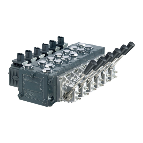
Danfoss PVG 32 Guide D'installation
Masquer les pouces
Voir aussi pour PVG 32:
- Guide d'installation (9 pages) ,
- Guide d'installation (9 pages)
Publicité
Liens rapides
Installation Guide
Proportional Valve
PVG 32
Identifikation, Identification
Standardmontage
: PVP til venstre for PVM
Standard installation : PVP to the left of PVM
Normale Montage
: PVP links von PVM
Montage standard
: PVP à gauche de PVM
PVP
F
E
PVM
Montering og orientering af stik
Installation and plug orientation
Montage und Ausrichtung des Steckers
Montage et orientation de la prise
PVB
1
2
L
82
130
mm
L
3.23
5.12
7.01
in
© Danfoss A/S, 2015-05
All manuals and user guides at all-guides.com
PVEH/
PVES
PVLP/PVLA
PVEA
PVB
PVEO
PVBZ
PVS
PVH
G
C
D
G
L
40 Nm
[354lbf•in]
A
N
B
N
LX
4 x M8 x min.10
[4x 5/16-18 UNC min. x 0.39]
In particularly exposed applications, protection in the form
of screening of the electrical actuator is recommended
3
4
5
6
178
226
274
322
8.90
10.79
12.68
520L0412 • Rev CE • May 2015
C: PVG-nummer, uge og år for montage
D: PVP-trykindstilling
E: PVP-nummer, uge og år for fremstilling
F: PVB - A-port, nummer, uge og år for
G: PVM, uge og år for fremstilling
C: PVG-number, week and year of
D: PVP - pressure setting
E: PVP-number, week and year of
F: PVB - A-port, number, week and year
G: PVM, week and year for manufacturing
C: PVG-Nummer, Woche und Jahr der
D: PVP - Druckeinstellung
E: PVP-Nummer, Woche und Jahr der
F: PVB - A-Anschluß, Nummer, Woche
PVMD
PVMR/
PVMF
G: PVM, Woche und Jahr der Herstellung
C: PVG-numéro, semaine et année de
D: PVP - réglage de pression
E: PVP-numéro, semaine et année de
F: PVB - orifice-A, numéro, semaine et
G: Semaine et année de fabrication
V310165.A
PVS: 20Nm
[177lbf•in]
PVSI: 40 Nm
[354lbf•in]
M
A
1
B
1
7
8
9
10
370
418
466
514
14.57
16.46
18.35
20.24
og serienummer
og serienummer
fremstilling og serienummer
installation and series number
manufacturing and series number
of manufacturing and series number
Montage und Seriennummer
Herstellung und Seriennummer
und Jahr der Herstellung und Serien-
nummer
montage et numéro sériel
fabrication et numéro sériel
année de fabrication et numéro sériel
V310139.A
* Plads til demontage
* Room for dismantling
* Platz für Demontage
* Espace pour démontage
V310115.A
1
Publicité

Sommaire des Matières pour Danfoss PVG 32
- Page 1 * Plads til demontage * Room for dismantling * Platz für Demontage * Espace pour démontage 3.23 5.12 7.01 8.90 10.79 12.68 14.57 16.46 18.35 20.24 © Danfoss A/S, 2015-05 520L0412 • Rev CE • May 2015...
- Page 2 300 bar [4351 psi] PVG 32 w. PVSI 350 bar [5076 psi] PVG 32 w. PVBZ 210 bar [3046 psi] PVG 32 w. HIC steel 350 bar [5076 psi] PVG 32 w. HIC aluminium 210 bar [3046 psi] PVG 120/32 w. PVS 300 bar [4351 psi] PVG 120/32 w.
- Page 3 Relief valve 1 360º~120 bar 360º~100 bar 360º~1740 psi 360º~1450 psi V310149.A Before week 40/2003 Week 40/2003 - week 2/2004 After week 2/2004 Relief valve 1 Relief valve 2 © Danfoss A/S, 2015-05 520L0412 • Rev CE • May 2015...
- Page 4 F : Branch circuit for fault indication F : Anzapfung von der Fehlerüberwachung PVEM F : Prise du surveillance de défaut NC: Ikke tilsluttet PVEO NC: Not connected NC: Nicht eingeloggt NC: Pas connecté V310116.A 520L0412 • Rev CE • May 2015 © Danfoss A/S, 2015-05...
- Page 5 (pin 2) = 0.5 • U Q: P -> A (pin 2) = (0.5 -> 0.25) • U Q: P -> B (pin 2) = (0.5 -> 0.75) • U © Danfoss A/S, 2015-05 520L0412 • Rev CE • May 2015...
- Page 6 E : Interrupteur d’arrêt d’urgence F : Udtag fra fejlovervågning F : Branch circuit for fault indication F : Anzapfung von der Fehlerüberwachung F : Prise du surveillance de défaut 520L0412 • Rev CE • May 2015 © Danfoss A/S, 2015-05...
- Page 7 (pin 1) = 0.5 • U (pin 1) = (0.5 -> 0.75) • U Q: P -> A Q: P -> B (pin 1) = (0.5 -> 0.25) • U © Danfoss A/S, 2015-05 520L0412 • Rev CE • May 2015...
- Page 8 B: Electrodistributeur Fejltilstand Error condition Fehlerzustand Condition erronée Aktiv fejlovervågning Active fault monitoring Aktive Fehlerüberwachung Active défault monitoring Passiv fejlovervågning Passive fault monitoring Passive Fehlerüberwachung Passiv défault monitoring Block diagram 520L0412 • Rev CE • May 2015 © Danfoss A/S, 2015-05...
- Page 9 Transducer omdrejning Håndtagsbevægelse Turn of transducer Movement of lever Transducerdrehung Hebelbewegung Rotation du transducteur Mouvement du manipulateur 1.5 mm [0.06 in] 3.0 mm [0.12 in] 4.5 mm [0.18 in] © Danfoss A/S, 2015-05 520L0412 • Rev CE • May 2015...
- Page 10 Abschirmung empfohlen. Dans les zones particulièrement lignende. particularly moist conditions. exposées, il est cependant conseillé de protéger le PVE à l’aide d’un écran ou d’un dispositif similaire. 520L0412 • Rev CE • May 2015 © Danfoss A/S, 2015-05...


