Publicité
Les langues disponibles
Les langues disponibles
Liens rapides
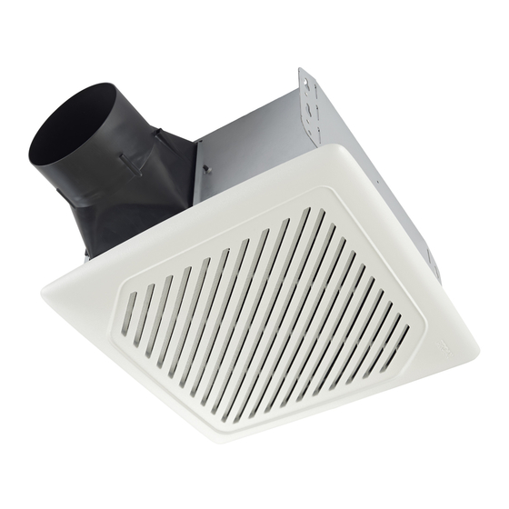
Humidity Sensing Fan
Ventilateur de détection d'humidité
Model number:
AER110S
Numéro de modèle :
INSTALLATION AND
USE & CARE INSTRUCTIONS
DIRECTIVES D'INSTALLATION,
D'UTILISATION ET D'ENTRETIEN
English - See page 2
Français - Voir page 9
© 2017 Broan Canada
99045947A
Publicité

Manuels Connexes pour Broan InVent AER110S


Sommaire des Matières pour Broan InVent AER110S
- Page 1 Humidity Sensing Fan Ventilateur de détection d’humidité Model number: AER110S Numéro de modèle : INSTALLATION AND USE & CARE INSTRUCTIONS DIRECTIVES D’INSTALLATION, D’UTILISATION ET D’ENTRETIEN English - See page 2 Français - Voir page 9 © 2017 Broan Canada 99045947A...
- Page 2 Please visit our website - www.broan.ca to register this product and to view installation tips and videos. Installer: Leave this manual with the homeowner. READ AND SAVE THESE INSTRUCTIONS WARNING CAUTION To reduce the risk of fire, electric • For general ventilating use only. Do not...
- Page 3 80%. If fan is still responding too often at feature. For odor or vapor control, the fan can be 80%, contact Broan Technical Support. energized by cycling the power switch. Once the fan has been energized in this manner, it will remain on To adjust the %HUMIDITY: for the set timer period.
- Page 4 ALL INSTALLATIONS Start here. 1. Remove blower and all packing material from fan WARNING housing. • Disconnect the electrical power supply and lock out the service panel. COOKING AREA Do not install above or inside this area. NOT FOR USE IN Cooking A COOKING AREA.
- Page 5 NEW CONSTRUCTION 5. Connect 4-in. round duct. For Retrofit Installation - Skip to Page 6. 3. Attach damper/duct connector to fan housing. Push connector through opening from inside of housing. Engage tabs and secure with screw from parts bag. 6. Connect wiring. Bend tab to expose desired access hole.
- Page 6 7. Install blower. Push grille up against ceiling. Re-install blower. Secure blower with 2 screws from parts bag and plug blower into black receptacle. Plug in humidity- sensing control. CAUTION • Make sure that the wiring inside of the housing does not interfere with re-installation of the blower.
- Page 7 5. Connect wiring. 7. Connect 4-in. round duct. Bend tab to expose desired access hole. Connect Pull existing ducting through housing discharge power cable to housing with appropriate UL approved opening. connector. Connect wires per diagram on page 8. Re- install wiring panel and secure with screw from parts Attach and tape ducting to duct connector.
- Page 8 WIRING DIAGRAMS WIRING OPTION #1 WIRING OPTION #2 • When switch is ON, fan will operate automatical- • When first switch (1) is ON, fan will operate auto- ly, based on room humidity conditions. matically based on room humidity conditions. • Turn fan ON immediately for the set timer period • Turn fan ON immediately (to control odors) by using (to control odors), by cycling switch.
- Page 9 Veuillez visiter site Web – www.broan.ca pour enregistrer ce produit et voir des conseils et vidéos d’installation. Installateur : Veuillez remettre ce manuel au propriétaire. LIRE CES DIRECTIVES ET LES CONSERVER AVERTISSEMENT ATTENTION Observez les directives ci-dessous afin • Pour ventilation générale de réduire les risques d’incendie, de choc...
- Page 10 50%. Si le ventilateur répond trop souvent à l’évolution changent. des conditions d’humidité, réglez vers 80%. Si le ventilateur répond encore trop souvent à 80%, contacter le support technique Broan. MISE EN MARCHE MANUELLE AVEC Pour régler l’humidité %HUMIDITY : ARRÊT DIFFÉRÉ...
- Page 11 TOUS LES TYPES DE POSE 1. Retirez le ventilateur et tout le matériel d’emballage du Commencez ici. boîtier du ventilateur. AVERTISSEMENT • Couper l’alimentation électrique et verrouiller le panneau de service. ZONE DE CUISSON Ne pas installer au-dessus ou à l'intérieur de cette zone.
- Page 12 CONSTRUCTION NEUVE 5. Connectez un conduit rond de Pour une rénovation - passez à la page 13. 10 cm (4 po). 3. Fixez le clapet/raccord de conduit au boîtier de ventilateur. Poussez le raccord au travers de l’ouverture par l’intérieur du boîtier. Engagez les ergots et fixez le tout avec les vis se trouvant dans le sachet de pièces.
- Page 13 7. Installez le ventilateur. Poussez la grille contre le Reposez le ventilateur. Fixez-le avec 2 vis du plafond. sachet de pièces et branchez-le dans la prise noire. Branchez le contrôle de l’humidité de détection. ATTENTION • Assurez-vous que le câblage à l’intérieur du boîtier n’empêche pas RÉNOVATION de remettre le ventilateur en place.
- Page 14 5. Branchez les fils. 7. Connectez un conduit rond de 10 cm (4 po). Repliez la languette pour exposer le trou d’accès voulu. Fixez le câble d’alimentation au boîtier à l’aide Tirez le conduit existant au travers de l’ouverture du connecteur approprié homologué UL. Connecter de sortie du boîtier.
- Page 15 SCHÉMAS DE CÂBLAGE CÂBLAGE OPTION # 1 CÂBLAGE OPTION # 2 • Lorsque commutateur est ON, ventilateur • Lorsque premier commutateur (1) est ON, le venti- fonctionne automatiquement, en fonction des lateur fonctionne automatiquement en fonction des conditions d’humidité ambiante. conditions d’humidité...