Fujioh BUF-01A Manuel D'installation
Masquer les pouces
Voir aussi pour BUF-01A:
- Manuel d'installation (2 pages) ,
- Mode d'emploi (24 pages)
Publicité
Les langues disponibles
Les langues disponibles
Liens rapides
1U03 2384
Model: BUF-01A/02A
SAFETY INSTRUCTIONS
Before installation and operation, read these instructions carefully
and use this product only in the manner described by the
manufacturer in the operation manual.
The instruction shown below are used to alert you to potential
personal injury and property damage hazards.
There are three hazard classifications based on potentially
dangerous situations.
Obey all safety instructions that show these symbols to avoid
possible injury, death and property damage.
WARNING:
WARNING indicates a potentially
hazardous situation which, if not
avoided, could result in death or
serious injury.
CAUTION:
CAUTION indicates a potentially
hazardous situation which, if not
avoided, may result in minor or
moderate injury.
CAUTION:
CAUTION used without the safety
alert symbol indicates a potentially
hazardous situation which, if not
avoided, may result in property
damage.
NOTE: The safety instructions are explained with the following
pictographic symbols.
means prohibition. It indicates actions, if any,
that mustn't be done.
means forcible execution. It indicates actions, if
any, that must be done.
WARNING
1. TO REDUCE THE RISK OF FIRE, ELECTRIC
SHOCK, OR INJURY TO PERSONS, OBSERVE
THE FOLLOWING:
a) Use this unit only in the manner intended by the
manufacturer. If you have questions, contact the
manufacturer.
b) Before servicing or cleaning unit, switch power
off at service panel and lock the service
disconnecting means to prevent power from being
switched on accidentally. When the service
disconnecting means cannot be locked, securely
fasten a prominent warning device, such as a tag,
to the service panel.
2. To reduce the risk of fire or electric shock, do not
use this product with any solid-state speed control
device.
3. TO REDUCE THE RISK OF FIRE, ELECTRIC
SHOCK, OR INJURY TO PERSONS, OBSERVE
THE FOLLOWING:
a) Installation work and electrical wiring must be
done by a qualified person(s) in accordance with
all applicable codes and standards, including fire-
rated construction.
1. Preparation
WARNING:
• If the range hood is not installed properly, it could become detached
and fall.
• Ensure that the metal duct does not touch other metal housing
materials, otherwise fire or electric shock could result.
1
According to the conditions where
Roof cap
6" round duct
the range hood is installed,
(For vertical
determine whether it will be
discharge)
discharged vertically or horizontally
(6" Round duct). For vertical or
horizontal discharge, run duct work
Soffit
between the hood location and the
roof cap or wall cap. For best result
in either direction, use a minimum
number of transitions and elbows.
Be sure to attach a roof cap or wall
cap to avoid rain/wind entry.
Range hood
2
The range hood unit must be mounted to a liner which has the
following dimensions. Install the liner securely after checking that
the opening size of the liner is the same as the figure below.
Front
Liner Dimensions (Unit: inch)
18-11/16"
17-1/2"
Liner
4-∅1/4"
Holes for mounting range hood
Center line
Range hood cutout
CAUTION:
• The liner shape illustrated in this installation manual is only for
reference.
CAUTION:
• When the liner is installed in the wooden hood, the inside of the
wooden hood placed above the cooking surface must be fully
covered by the metal barrier including bottom edges. Select a
suitable liner and metal barrier according to the size and shape of
the wooden hood and install properly.
• The liner should be installed tightly. If the liner installation is not
correct, the range hood unit may become detached and fall.
3
Run house wiring between service panel and hood location.
4
Prepare the range hood unit.
Tape
Exhaust pipe
(1) The range hood is supplied
with the exhaust pipe fixed
on its top plate.
(2) Detach the tape stuck on
the exhaust pipe.
(3) Arrange the ends of
6" round duct and
wiring conduit so that
they can connect
5-7/8"
with the top of the
range hood.
5-3/16"
(4) Be sure to keep 1-3/16"
Duct
overlapping length of the
pipe and duct.
1-3/16"
Range hood
unit
Liner
Range Hood
INSTALLATION MANUAL
b) Sufficient air is needed for proper combustion and
exhausting of gases through the flue (chimney) of
fuel burning equipment to prevent back drafting.
Follow the heating equipment manufacturer's
guidelines and safety standards such as those
published by the National Fire Protection Association
(NFPA), and The American Society for Heating,
Refrigeration and Air Conditioning Engineers
(ASHRAE), and the local code authorities.
c) When cutting or drilling into wall or ceiling, do not
damage electrical wiring and other hidden utilities.
d) Ducted fans must always be vented to the
outdoors.
e) This unit is designed for ducted or ductless
installation. When ductless kit part numbers
FDK-02A is installed, this unit is certified ductless.
The end user is responsible to ensure compliance
with all Federal, State and Local Environmental
and Fire codes.
4. TO REDUCE THE RISK OF FIRE, USE ONLY
METAL DUCTWORK.
5. This unit must be grounded.
6. Check that the hood is correctly installed, since
incorrect installation could result in the range hood
becoming detached and falling off.
7. Connect only to an AC120 Volt power source or
the range hood could result in fire, electric shock,
and damage.
CAUTION
1. For general ventilating use only. Do not use to
exhaust hazardous or explosive material and
vapors.
2. To reduce the risk of fire and to properly exhaust
air, be sure to duct air outside. Do not vent exhaust
air into spaces within walls or ceilings or into attics,
crawl spaces, or garages.
3. Read specification label on this product for further
information and requirements.
4. Use only for the purpose of kitchen ventilation.
5. Do not install this range hood in the bathroom or
in other wet rooms since electrical shock and
damage may result.
6. Fasten the filter and other parts securely. Incorrect
attachment may result in personal injury or
property damage.
7. Keep your hands and other objects away from
the fan while it is in motion. The range hood may
injure you or damage itself.
(5) Remove 4 screws to detach the front cover.
Then, turn it over and remove 2 cushions of foamed
polystyrene put on its both ends.
Front cover
Wall cap
6" round duct
(For horizontal
WARNING:
discharge)
• Remove the cushions without fail, otherwise there is a risk of fire.
2. Range Hood Mounting
CAUTION:
• Wear working gloves to avoid injury.
1
Hold up the range hood and insert it into the opening of the liner.
When the 4 securing plates on both sides have passed through
the top of the liner, turn them outward to secure the range hood
on the liner temporarily. Make sure the top of the exhaust pipe is
inserted into the bottom of the duct.
Duct
Range hood unit
Liner
Securing
plate
Securing plate turns
Detach
while passing through
the tape
the opening of Liner
Range hood unit
2
Align 4 screw holes of the liner and range hood unit, then fix
securely using the supplied screws and nuts.
Note: Fasten all the screws and nuts evenly.
Nut with plate
[Right & left,
Each two (2) places]
Range hood unit
Liner
Four (4) screws
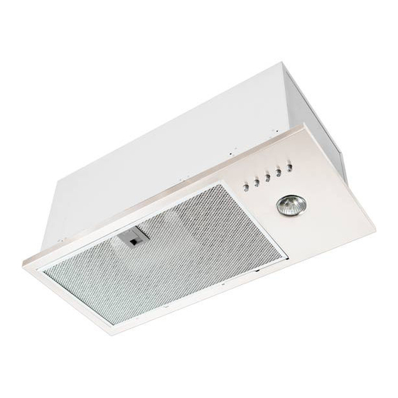
NAMES OF PARTS
Enclosure
Front cover
Lamp
(standard MR16-GU10, 50Watt)
(not supplied)
ACCESSORIES
Screw M5×30
Four (4) pieces
DIMENSIONS
18-11/16"
5-3/16"
6-11/16"
17-1/4"
5-7/8"
19-11/16"
4-15/16"
INSTALLATION
3
Make the duct joint secure and air tight using non-flammable
tape such as duct tape, etc. (not supplied)
Note: Make sure that the shutter installed in the exhaust pipe
moves freely.
Cushion
3. Connecting Power Supply Wires
WARNING:
• Electrical wiring should be done by a qualified person(s) in
accordance with all applicable codes and standards, including
fire-rated construction. An unqualified person doing the work could
result in fire, electric shock or injury.
• This range hood uses 120V AC. Do not connect to other voltage
since fire, electric shock or damage could result.
1
Remove the nut (not supplied) from
the conduit connector at the end of
power wiring.
WARNING:
Be sure to switch power OFF at service panel before wiring.
2
Connect the conduit through the connecting hole of the enclosure
using the nut previously removed.
Duct
Securing plate
[each side
two (2) places]
Liner
Liner
3
Connect the electrical wires as follows:
Connect wires tightly and securely using wire connectors
(not supplied).
• Black to Black
• White to White
Nut with plate
CIRCUIT DIAGRAM
Switch
Connector
Black
120V
White
60Hz
White
Filter
Green
Capacitor
RANGE HOOD LOCATION
1
The range hood must be installed just above the cooktop.
Nut with plate
Four (4) pieces
2
The minimum distance from the cooking surface to the bottom of the
range hood must be 24".
(Unit: inch)
4-1/4"
Holes for mounting range hood
3
The total weight of the BUF-01A/02A range hood unit is 18 lbs. (8 kg)
4
Power requirements are:
BUF-01A: AC120 V, 60 Hz, 1.5 Amp
BUF-02A: AC120 V, 60 Hz, 2.1 Amp
WARNING:
• Check that the hood is correctly installed, since incorrect installation
could result in the detachment of the range hood and the unit could fall.
CAUTION:
• To protect hands from injury, wear working gloves when installing the
range hood.
4. Final Assembly and Check
1
Assembly
(1) Replace the front cover with 4 screws.
To prevent the screw holes from being damaged, be sure
not to over tighten the screws (with the torque of 13 inch-lbs.
[1.5 N-m] or less).
(2) One 50Watt halogen light bulb (not supplied) can be mounted
in this range hood.
Prior to function check, install light bulb (Bulb type standard
MR16-GU10), rated 120V - 50Watt or below.
The following light bulbs are recommended for this range
hood.
• GE Model No. Q50GU10/FL/CD
• PHILIPS Model No. Twistline 50W GU10 120V MR16
Turn the lamp clock-wise to install.
Front cover
Lamp
(standard MR16-GU10, 50Watt)
(not supplied)
2
Check
(1) Turn on the electrical circuit to the range hood.
(2) Make sure that the switch and light operate correctly.
Refer to page 5 of the Operation Manual.
Conduit
(3) Make sure that the range hood has no abnormal noises and/
or vibration.
CAUTION:
• To reduce the risk of injury, keep your hands and other objects
away from the fan while it is in motion.
• Wear working gloves to avoid injury.
• Green to Green
5. Explanation to the End User
(1) Referring to the Operation Manual, explain the operation of this
range hood to end users.
(2) The Installation Manual and Operation Manual should be given to
the end user.
Motor
Fan Switch
Connector
Pilot Lamp
Connector
Black
Grey
Yellow
Red
Yellow
Yellow
White
Connector
White
Red
Black
Lamp:50W
Connector
White
Note: When installing
the bulb, be sure
to fix to the socket
securely.
Lamp
Push the lamp,
and turn it
clock-wise.
Push to turn ON
Publicité

Manuels Connexes pour Fujioh BUF-01A

Sommaire des Matières pour Fujioh BUF-01A
- Page 1 When the service The total weight of the BUF-01A/02A range hood unit is 18 lbs. (8 kg) disconnecting means cannot be locked, securely 4. Use only for the purpose of kitchen ventilation.
- Page 2 3. Lisez l’étiquette des spécifications de cet appareil pour service ne peut pas être coupé, fixez un moyen des informations et renseignements supplémentaires. Le poids total de la hotte d’aspiration BUF-01A/02A est : 18 lbs. (8 kg) d’avertissement visible, comme une étiquette, sur le panneau de service.