
Manuels Connexes pour PR 9116


Sommaire des Matières pour PR 9116
- Page 1 9 1 1 6 C o n v e r t i s s e u r u n i v e r s e l N o 9 1 1 6 V 1 0 2 - F R V e r s i o n d e p r o d u i t : 9 1 1 6 - 0 0 2 S I G N A L S T H E B E S T...
- Page 2 PR electronics A/S tilbyder et bredt program af analoge og digitale signalbehandlingsmoduler til industriel automation. Programmet består af Isolatorer, Displays, Ex-barrierer, Temperaturtransmittere, Universaltransmittere mfl. Vi har modulerne, du kan stole på i selv barske miljøer med elektrisk støj, vibrationer og temperaturud- sving, og alle produkter opfylder de strengeste internationale stan- darder.
-
Page 3: Table Des Matières
Déclaration de conformité CE ..........Options avancées............... Fonctions ................Caractéristiques techniques..........Applications ................ PR 4501 indicateur / façade de programmation....Références de commande ..........Spécifications ..............Configuration du contrôle d’erreur de câble ...... 13 Signal d’entrée hors d’échelle ......... 14 Détection erreur capteur .......... -
Page 4: Avertissement
à remplacer les fusibles. AVERTISSEMENT Ne pas ouvrir la plaque avant du module au risque d’endommager le connecteur de l’indicateur / la façade de programmation PR 4501. Ce module ne contient ni de commutateurs DIP ni de cavaliers. SIGNIFICATION DES SYMBOLES Triangle avec point d’exclamation : Attention ! Lire ce manuel avant... -
Page 5: Reception Et Deballage
à proximité du module et facile d’accès. Ce bouton doit être étiqueté avec la mention : peut couper la tension du module. Pour une installation sur le rail d’alimentation 9400, le module sera alimenté par le contrôleur d’alimentation 9410. 9116 - Product Version 9116-002... -
Page 6: Démontage Du Système 9000
Dans la mesure où les instructions de ce guide ne sont pas strictement respectées par le client, ce dernier n’est pas en droit de faire une réclamation auprès de PR electronics SARL, même si cette dernière figure dans l’accord de vente conclu. -
Page 7: Déclaration De Conformité Ce
: EN 60079-0 : 2009 Organisme notifié : KEMA Quality B.V. (0344) Utrechtseweg 310, 6812 AR Arnhem P.O. Box 5185, 6802 ED Arnhem The Netherlands Rønde, le 27 juin 2012 Kim Rasmussen Signature du fabricant 9116 - Product Version 9116-002... -
Page 8: Convertisseur Programmable À Seuils, [Ex Ia]
• Configuration avancée du relais, p.ex. consigne, fenêtre, délai, détection erreur capteur et surveillance de l’alimentation. • Recopie de la configuration d’un module à d’autres du même type à l’aide de la façade de programmation. • Caractéristiques S.I. d’Uo réduites à < 8,3 V pour des signaux d’entrée actives. • Les entrées TC peuvent utiliser soit la CSF interne soit le bornier avec capteur Pt100 incorporé (PR 5910Ex, voie 1 / PR 5913Ex, voie 2) pour une précision améliorée. • Le 9116 détecte automatiquement s’il doit fournir un signal de courant actif ou passif. Fonctions • Le module peut être installé dans la zone non-dangereuse et en zone 2/div. 2 et recevoir des signaux de la zone 0, 1, 2, 20, 21 et 22 / Class I/II/III, Div. -
Page 9: Applications
Etat du module N.F. Etat du module Alimentation Zone 0, 1, 2, par rail 20, 21, 22 / Cl. I/II/III, div. 1 Zone 2 / Cl. 1, div. 2, gr. A-D ou zone non-dangereuse gr. A-G 9116 - Product Version 9116-002... -
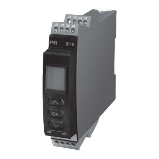
Page 10: Pr 4501 Indicateur / Façade De Programmation
Point statique = verrouillage SIL, point clignotante = aucun verrouil- lage SIL. • L’accès à la programmation peut être bloqué par un mot de passe. Ce mot de passe est sauvegardé dans le module afin d’assurer un haut niveau de protection contre les modifications non autorisées. Montage / installation • Cliquer le 4501 sur la face avant du 9116. 9116 - Product Version 9116-002... -
Page 11: Références De Commande
Temps de réponse (0...90%, 100...10%) : Entrée température, programmable ..1...60 s Entrée mA / V, programmable ....0,4...60 s Température d’étalonnage ......20...28°C Précision, la plus grande des valeurs générales et de base : Valeurs générales Type Précision Coefficient de d’entrée... -
Page 12: Coefficient De Température
Dimensions, sans façade 4501 (HxLxP) ..109 x 23,5 x 104 mm Dimensions, avec façade 4501 (HxLxP) ..109 x 23,5 x 116 mm Degré de protection ........IP20 Poids ............185 g / 200 g avec 4501 9116 - Product Version 9116-002... - Page 13 +900°C DIN 43710 -180°C +1300°C IEC 60584-1 -50°C +1760°C IEC 60584-1 -50°C +1760°C IEC 60584-1 -200°C +400°C IEC 60584-1 -200°C +600°C DIN 43710 0°C +2300°C ASTM E988-90 0°C +2300°C ASTM E988-90 -200°C +800°C GOST 3044-84 9116 - Product Version 9116-002...
- Page 14 Stabilité de charge ........≤ 0,01% de l’EC / 100 Ω Résistance de charge ........≤ (V -3,5) / 0,023 A [Ω] alimentation Gamme d’alimentation externe pour transmetteur 2-fils....... 3,5...26 Vcc Effet d’une variation de la tension d’alimentation externe 2-fils ...... < 0,005% de l’EC / V 9116 - Product Version 9116-002...
-
Page 15: Configuration Du Contrôle D'erreur De Câble
UL, Standard for Safety ......UL 61010-1 SIL .............IEC 61508 EC = Echelle configurée Configuration du contrôle d’erreur de câble Sensor error check: Module: Configuration Détection erreur capteur : ERR.ACT=NONE - OUT.ERR=NONE. 9116 Autre : 9116 - Product Version 9116-002... -
Page 16: Indication Dans Le 4501 De : Signal D'entrée Hors D'échelle
LIN.R Pour R lin._0%≥ env. 18 Ω SE.SH Court circuit capteur Rupture capteur ou Tous SE.BR resistance de ligne trop haute TEMP Pt100 à Pt1000 et Ni50 à Ni1000 SE.SH Court circuit capteur 9116 - Product Version 9116-002... -
Page 17: Indications Erreur Matériel
Erreur aliment. du CPU prin.* Erreur matériel MP.ER Erreur ProgFlow du CPU prin.* Erreur de l’autotest d’initialisation Erreur matériel MI.ER principale Erreur matériel DE.ER Erreur du module* Somme de contrôle de code non Erreur matériel FC.ER valable en 4501 9116 - Product Version 9116-002... - Page 18 OK. L’erreur est corrigée en déconnectant et puis reconnectant l’alimentation du module. ** L’erreur peut être négligée en sélectionnant un type d’entrée autre que TC. *** L’erreur est corrigée en parcourant les menus. 9116 - Product Version 9116-002...
-
Page 19: Connexions
51 52 53 54 51 52 53 54 51 52 53 54 Sortie : Courant Transmetteur 2-fils Relais (sortie active) (sortie passive) 11 12 13 14 11 12 13 14 11 12 13 14 N.O. 9116 - Product Version 9116-002... -
Page 20: Schéma De Principe
SCHEMA DE PRINCIPE 9116 - Product Version 9116-002... -
Page 21: Indications D'erreur Signal Et Câble Sans La Façade 4501
Relais de sortie exité Fermé Clignotante Clignotante Désexcité par court circuit / rupture (si activé) Relais de sortie désexité Fermé Clignotante Clignotante Désexcité par court circuit / rupture (si activé) Relais de sortie désexité Clignotante Excité Ouvert 9116 - Product Version 9116-002... -
Page 22: Programmation / Operation Des Touches De Fonction
OPERATION DES TOUCHES DE FONCTION Documentation pour le diagramme de programmation. Généralités Lors de la configuration du 9116 vous êtes guidés tout au long des paramètres du menu ; ainsi vous pouvez choisir le réglage qui correspond à votre application. Pour chaque menu il y a un texte d’aide qui défile en ligne 3 de l’indicateur. -
Page 23: Informations Relatives À L'erreur De Câble Sur La Façade 4501
CSF (CJC) Dans le menu CJC vous pouvez choisir entre connecteur CSF ou compensation de soudure froide interne. Le connecteur CSF (PR 5910Ex) est à commander séparemment. Informations relatives à l’erreur de câble sur la façade 4501 Erreur de câble (voir limites dans tableau) est affiché par CA.BR (rupture câble) ou CA.SH (court circuit câble). -
Page 24: Fonctions Avancées
à l’aide des flèches et ainsi contrôler le signal de sortie haut et bas ou l’état du relais OFF et ON. Vous devez sortir du menu en pressant 3 (pas de time-out). La simulation sera terminée, si le 4501 est enlevé. 9116 - Product Version 9116-002... - Page 25 Rail d’alimentation : Dans le menu ”RAIL” vous pouvez choirsir si des erreurs capteur doivent être transmis à l’unité de surveillance du module PR 9410 Contrôleur d’alimentation. Safety Integrity Level (SIL): Voir le ”Safety Manual” (en Anglais) pour information supplémentaire.
- Page 26 Txt 6 Continué à la page Diagramme de TC.B TC.E TC.J TC.K programmation TC.L TC.N TC.R TC.S TC.T TC.U TC.W3 ADV.SET CONN TC.W5 TC.Lr TC.K ADV.SET SENSOR TC.TYPE Txt 2 Txt 10 Txt 18 Txt 31 9116 - Product Version 9116-002...
-
Page 27: Diagramme De Programmation
1 Incrémenter la valeur / choisir paramètre suivant 2 Décrémenter la valeur / choisir paramètre précédent 3 Valider les valeurs choisies et fin du menu Maintien 3 Retour au menu précédent / retour au menu 1.0 sans sauvegarde 999.9 DISP -199.9... - Page 28 REL.FUN Txt 19 20-4 20-0 23mA 4-20 850.0 0/3.5mA 0-20 -200 -199.0 NONE 4-20 23mA 150.0 O.RANGE OUT.ERR OUT.LO OUT.HI RESP. Txt 37 Txt 38 Txt 41 Txt 42 Txt 39 Retour au menu 1.0 9116 - Product Version 9116-002...
-
Page 29: Diagramme De Programmation, Reglage Avance (Adv.set)
Vérification de la 9999 LOCK configuration SIL 2008 LOCK SETUP EN.SIL NEW.PAS CONFIG SIL.OK Txt 43 Txt 64 Txt 55 Txt 66 ....9116 - Product Version 9116-002... -
Page 30: Menu Déroulant En Ligne 3 De L'indicateur
Simulation relais - utiliser 1 pour alterner l’état du relais d’alimentation OK [54] Permettre protection par mot de passe ? Sélectionner Fonction ERREUR - le relais indique [55] Entrer Nouveau mot de passe uniquement erreur capteur [56] Permettre la fonctionalité Réglage rapide ? 9116 - Product Version 9116-002... - Page 31 Erreur dans la mémoire FLASH - contrôler la configuration [89] Configuration ou version invalide [90] Erreur matériel [91] Erreur du capteur CSF - contrôler la température du module [92] Erreur CSF - contrôler le bornier CSF [93] Pas de communication 9116 - Product Version 9116-002...
-
Page 32: Graphique Descriptif De La Fonction Fenêtre
Graphique descriptif de la fonction fenêtre 9116 - Product Version 9116-002... -
Page 33: Graphique Descriptif De La Fonction Consigne
Graphique descriptif de la fonction consigne Signal Délai ON d’entrée Délai OFF Consigne (croissante) Hystérésis Temps Relais On Fermé Contact (N.O.) Ouvert 9116 - Product Version 9116-002... -
Page 34: Appendix
APPENDIX IECEx Installation drawing ATEX Installation drawing FM Installation drawing Safety manual 9116 - Product Version 9116-002... - Page 35 For Installation in Zone 2 / Division 2 the following must be observed. The 4501 programming module is to be used solely with PR electronics modules. It is important that the module is undamaged and has not been altered or modified in any way. Only 4501 modules free of dust and moisture shall be installed.
- Page 36 If the sensor circuits or loop supply circuits have been installed in a type of protection other than “Intrinsic Safety”, the module shall not be reinstalled in type of protection “Intrinsic Safety” Revision date: Version Revision Prepared by: Page: 2010-02-12 V5 R0 9116 - Product Version 9116-002...
- Page 37 Term. 54-52; 51-52 21.4 V 0.16 μF 4 mH 54 μH/Ω 93 mA 1.13 μF 16 mH 218 μH/Ω 650 mW 4.15 μF 32 mH 436 μH/Ω Revision date: Version Revision Prepared by: Page: 2010-02-12 V5 R0 9116 - Product Version 9116-002...
- Page 38 Lo/Ro Term. 52-51, 51-52 16.6 V 0.4 μF 100 mH 25mH/Ω 0.2 mA 2.3 μF 100 mH 100mH/Ω 0.8 mW 9.5 μF 100 mH 200mH/Ω Revision date: Version Revision Prepared by: Page: 2010-02-12 V5 R0 9116 - Product Version 9116-002...
-
Page 39: Schéma D'installation Atex
Pour l'installation dans la zone 2 / Division 2 on doit observer ce qui suit. Le module de programmation 4501 doit être employé seulement avec des modules de PR electronics. Il est important que le module soit intact et n'ait pas été changé ou n'ait pas été... - Page 40 Selon le type de protection « sécurité intrinsèque iD » les paramètres pour la sécurité intrinsèque pour le gaz IIB s'appliquent. Ne déconnecter pas les connecteurs une fois activé et dans un environnement en présence de gaz. Ne montez pas ou n'enlevez pas les modules du rail d’alimentation est présence d’un mélange de gaz.
- Page 41 Term. 54-52; 51-52 21.4 V 0.16 μF 4 mH 54 μH/Ω 93 mA 1.13 μF 16 mH 218 μH/Ω 650 mW 4.15 μF 32 mH 436 μH/Ω Revision date: Version Revision Prepared by: Page: 2010-02-12 V5 R0–FR01 9116 - Product Version 9116-002...
- Page 42 Lo/Ro Term. 52-51, 51-52 16.6 V 0.4 μF 100 mH 25mH/Ω 0.2 mA 2.3 μF 100 mH 100mH/Ω 0.8 mW 9.5 μF 100 mH 200mH/Ω Revision date: Version Revision Prepared by: Page: 2010-02-12 V5 R0–FR01 9116 - Product Version 9116-002...
-
Page 43: Fm Installation Drawing
For Installation in Zone 2 / Division 2 the following must be observed. The 4501 programming module is to be used solely with PR electronics modules. It is important that the module is undamaged and has not been altered or modified in any way. Only 4501 modules free of dust and moisture shall be installed. - Page 44 8) In type of protection “intrinsic safety iD” the parameters for intrinsic safety for gas group IIB are applicable. 9) Warning: Do not mount or remove modules from the Power Rail when an explosive gas mixture is present. Revision date: Version Revision Prepared by: Page: 2010-02-12 V5 R0 9116 - Product Version 9116-002...
- Page 45 IIC or A,B Io, Isc 93 mA 1.13 μF 16 mH 218 μH/Ω IIB or C,E,F 650 mW 4.15 μF 32 mH 436 μH/Ω IIA or D,G Revision date: Version Revision Prepared by: Page: 2010-02-12 V5 R0 9116 - Product Version 9116-002...
- Page 46 IIC or A,B Io, Isc 0.2 mA 2.3 μF 100 mH 100mH/Ω IIB or C,E,F 0.8 mW 9.5 μF 100 mH 200mH/Ω IIA or D,G Revision date: Version Revision Prepared by: Page: 2010-02-12 V5 R0 9116 - Product Version 9116-002...
-
Page 47: Safety Manual
Safety manual unIVeRSal COnVeRteR 9116 this safety manual is valid for the following product versions: 9116-002 9116-001 Version No. V2R0... - Page 48 9116 UNiVeRsal coNVeRteR safety Manual 0 COntentS 1 observed standards ..................... 2 acronyms and abbreviations ..................3 Purpose of the product ....................4 assumptions and restrictions for use of the product ..........4.1 Basic safety specifications .................. 4.2 safety accuracy ....................4.2.1 Minimum span ..................4.2.2 Range limitations ..................4.3 associated equipment ..................4.3.1 RtD or linear resistance sensor wiring ............ 4.3.3 Process calibration .................. 4.3.4 analogue output ..................4.3.5 Relay output ..................... 4.4 Failure rates ......................
- Page 49 9116 UNiVeRsal coNVeRteR 15 Fault reaction and restart condition ................16 User interface ....................... 16.2 Routing diagram ....................16.3 Routing diagram - advanced settings (aDV.set)..........17 connections diagram ....................Version No. V2R0...
-
Page 50: Observed Standards
9116 UNiVeRsal coNVeRteR safety Manual Observed standards standard Description Functional safety of electrical / electronic / programmable electronic iec 61508 safety-related systems iec 61508- Part 2: Requirements for electrical / electronic / programmable electronic 2:2000 safety-related systems iec 61508- Part 3: software requirements 3:1998 iec 61326-3- immunity requirements for safety-related systems 1:2008 acronyms and abbreviations acronym / Designation Description abbreviation term defined by iec 61508 as “part of a subsystem comprising a single component or any element group of components that performs one or more element safety functions” this is the likelihood of dangerous safety function Probability of Failure PFD failures occurring on demand. on Demand the term “Probability” is misleading, as iec Probability of danger- 61508 defines a Rate. ous Failure per Hour... -
Page 51: Assumptions And Restrictions For Use Of The Product
9116 UNiVeRsal coNVeRteR assumptions and restrictions for use of the product Basic safety specifications operational temperature range.... -20...+60°c storage temperature range...... -20...+85°c Power supply type, min...... Double or reinforced supply voltage ......... 19.2...31.2 VDc Relay output pulse length, min....70 ms loop supply .......... >16.5 V @ 20 ma external loop supply voltage .... 5...26 VDc + external drop (Passive output) Mounting area .......... Zone 2 / Division 2 or safe area Mounting environment ...... Pollution degree 2 or better Safety accuracy the analogue output and relay output corresponds to the applied input within the safety accuracy. -
Page 52: Process Calibration
4.3.4 analogue output the connected safety Plc shall be able to detect and handle the fault indications on the analogue output of the 9116 converter by having a NaMUR Ne43-compliant current input. 4.3.5 Relay output the relay output shall only be connected to equiment which has a current limiting function of 2 a. -
Page 53: Functional Specification Of The Non-Safety Functions
9116 UNiVeRsal coNVeRteR For RtD and linear resistance input sensors, cable resistances of up to 50 W per wire can be compensated if 3- or 4-wire connection is configured. For thermocouple sensors, cold junction temperature errors can be compensated, either by an internally mounted temperature sensor, or by an accessory connector with a built-in temperature sensor. the selection of cJc measurement must be done and verified by the end user. functional specification of the non-safety functions the status relay (terminal 33 and 34), error signal on power rail (terminal 91) and leD outputs are not suitable for use in any safety instrumented Function. Safety parameters RtD, tc, linR and Potentiometer input, current output Probability of dangerous Failure per Hour (PFH) 4.30e-08 Note Probability of failure on demand (PFD) - 2.82e-04 1 year proof test interval Proof test interval (10% of loop PFD) 4 years safe Failure Fraction RtD, tc, linR and Potentiometer input, Relay output Probability of dangerous Failure per Hour (PFH) 6.20e-08 Note Probability of failure on demand (PFD) - 4.03e-04 1 year proof test interval Proof test interval (10% of loop PFD) 3 years safe Failure Fraction Voltage input, current output Probability of dangerous Failure per Hour (PFH) 5.60e-08... -
Page 54: Hardware And Software Configuration
Description of the “safe state”, relay output contact open (relay de-energized) Relay lifetime (Note 2 ) 100 000 times Note 1 : the 9116 contains no lifetime limiting components, therefore the PFH figures are valid for up to 12 years, according to iec 61508. Note 2 : the user must calculate the product lifetime with regard to the relay lifetime. Hardware and software configuration all configurations of software and hardware versions are fixed from factory, and cannot be changed by end-user or reseller. this manual only covers products labelled with the product version (or range of versions) specified on the front page. -
Page 55: Failure Category
9116 UNiVeRsal coNVeRteR failure category failure rates (1/h) for RtD, tc, linR and Potentiometer input, current output Fail safe Detected 0.000e-0 Fail safe Undetected 2.78e-07 Fail Dangerous Detected 3.52e-07 Fail Dangerous Undetected 4.30e-08 failure rates (1/h) for RtD, tc, linR and Potentiometer input, Relay output Fail safe Detected 0.000e-0 Fail safe Undetected 3.59e-07 Fail Dangerous Detected 2.30e-07 Fail Dangerous Undetected 6.20e-08 failure rates (1/h) for Voltage input, current output Fail safe Detected 0.000e-0 Fail safe Undetected 3.95e-07 Fail Dangerous Detected 4.79e-07... -
Page 56: Periodic Proof Test Procedure
Repair of the device and replacement of circuit breakers must be done by PR electronics a/s only. 12 maintenance No maintenance required. 13 Documentation for routing diagram the routing diagram is shown in section 16.2. 13.1 In general When configuring the 9116, you will be guided through all parameters and you can choose the settings which fit the application. For each menu there is a scrolling help text which is automatically shown in line 3 on the display. configuration is carried out by use of the 3 function keys: 1 will increase the numerical value or choose the next parameter 2 will decrease the numerical value or choose the previous parameter 3 will accept the chosen value and proceed to the next menu When configuration is completed, the display will return to the default state 1.0. Pressing and holding 3 will return to the previous menu or return to the default state (1.0) without saving the changed values or parameters. -
Page 57: Sensor/Cable Fault Information Via Display Front 4501
9116 UNiVeRsal coNVeRteR 13.2.2 Sensor/cable fault information via display front 4501 When the function is enabled and supported by selected input type, sensor or cable faults are displayed as se.BR (sensor break) or se.sH (cable short-circuited). in case of sensor or cable fault the backlight flashes. this can be reset by pressing the 3 key. When the sensor or cable fault has been remedied, the device will return to normal operation. 13.3 advanced functions (aDV.Set) the device gives access to a number of advanced functions which can be reached by answering “Yes” to the point “aDV.set”. -
Page 58: Simulation (Sim)
9116 UNiVeRsal coNVeRteR safety Manual 13.3.7 Simulation (SIm) it is possible to override the actual measured input signal by a simulated value. in the Rel.siM menu it is posible to simulate the relay state with out affecting the analogue output, by pressing . leaving the simulation menus, or disconnecting the 4501 device, will disable the simulation mode and bring the output back to correspond to the actual measured value. simulation is not possible in sil-mode. 13.3.8 Safety integrity level (SIl) - Page 59 9116 UNiVeRsal coNVeRteR Pt.tYPe Pt sensor type (for seNsoR = Pt): 10 = Pt10 20 = Pt20 (No short circuit detection!) 50 = Pt50 100 = Pt100 200 = Pt200 250 = Pt250 300 = Pt300 400 = Pt400 500 = Pt500 1000 = Pt1000 Ni.tYPe Ni sensor type (for seNsoR = Ni): 50 = Ni50 100 = Ni100 120 = Ni120 1000 = Ni1000 tc.tYPe thermocouple type (for seNsoR = tc): tc.B = thermocuple type B tc.e = thermocuple type e tc.J = thermocuple type J tc.K = thermocuple type K tc.l = thermocuple type l tc.N = thermocuple type N tc.R = thermocuple type R tc.s = thermocuple type s tc.t = thermocuple type t tc.U = thermocuple type U tc.W3 = thermocuple type W3 tc.W5 = thermocuple type W5 tc.lr = thermocuple type lr cJc type for seNsoR = tc: iNt = internal cJc sensor measurement coNN = cJc connector measurement (accessory) Version No. V2R0...
- Page 60 9116 UNiVeRsal coNVeRteR safety Manual coNNec selected sensor connection type for RtD or linear resistance measurements (for seNsoR = Ni or Pt or iN.tYPe = liN.R): 2W = 2-wire 3W = 3-wire 4W = 4-wire if 2W or 3W is selected, the end user must ensure that the applied sensor wiring does not introduce failures exceeding the requirements for the safety application. R 0% 0% input range for linear resistance measurements (for iN.tYPe = liN.R). this value must be < (R 100% - minimum span), refer to 4.2.1 R 100% 100% input range for linear resistance measurements (for iN.tYPe = liN.R) this value must be > (R 0% + minimum span), refer to 4.2.1 UNit selected temperature unit for iN.tYPe = teMP...
-
Page 61: Parameters Related To Relay Output
9116 UNiVeRsal coNVeRteR 14.1.2 Parameters related to Relay Output Rel.UNi Relay Units (for iN.tYPe ≠ teMP): PeRc = Relay setpoint in percent of input range. DisP = Relay setpoints and hysteresis values relates to DisP.lo and DisP.Hi (display units) Rel.FUN Relay Function: oFF (Note 3 ) = Relay is always oFF PoW (Note 3 ) = Relay is always oN if power is applied eRR = Relay is activated when sensor error is present WiND = Relay is activated when input signal is between setP. lo and setP.Hi values setP = Relay is activated when input signal reaches setP value coNtac. Relay contact function: N.c. = Normaly closed relay contact (for Rel.FUN = setP) N.o. = Normally open relay contact (for Rel.FUN = setP) o.i.W = Relay contact open inside Window (for Rel.FUN = WiND) c.i.W = Relay contact closed inside Window (for Rel.FUN = WiND) setP. Relay setpoint value in Rel.UNi units for iN.tYPe ≠ teMP or in UNit for iN.tYPe = teMP. (for Rel.FUN = setP) setP.lo Relay setpoint low value in Rel.UNi units for iN.tYPe ≠ teMP or in UNit for iN.tYPe = teMP. (for Rel.FUN = WiND) setP.Hi... -
Page 62: Parameters Related To Analouge Output
9116 UNiVeRsal coNVeRteR safety Manual eRR.act Relay sensor error action (for Rel.FUN = setP, WiND or eRR): only relevant if iN.tYPe = teMP, cURR and i.RaNGe = 4-20, PotM or liN.R and R 0% is ≥ 18. NoNe (Note 3 ) = sensor error detection Not enabled (Note 4 ), relay state at sensor error is undefined. (Not for Rel.FUN = eRR) oPeN = Relay contact is open at sensor error clos = Relay contact is closed at sensor error HolD (Note 3 ) = Relay contact holds the state as before sensor error occurred. (Not for Rel.FUN = eRR) oN.Del Relay oN delay from setP or setP.lo/Hi is crossed in units of seconds (for Rel.FUN = setP or WiND) oFF.Del Relay oFF delay from setP +/- HYst or setP.lo/Hi +/- HYst is crossed in units of seconds (for Rel.FUN = setP or WiND) Note 3 : Value not allowed if the relay is used in a safety application (eN.sil = Yes) and iN.tYPe = cUR and loop supply is used to supply a current input signal. Note 4 : error detection is enabled if oUt.eRR ≠ none, but relay state at sensor erroris undefined. 14.1.3. Parameters related to analouge output... -
Page 63: Verification Procedure
9116 UNiVeRsal coNVeRteR oUt.lo selected temperature value for 0% output for iN.tYPe = teMP in units defined by the UNit parameter (°c or °F) Range is defined by the selected temperature sensor (seNsoR and tc.tYPe, Ni.tYPe or Pt.tYPe), but value must be less than oUt.Hi - minimum span. oUt.Hi selected temperature value for 100% output for iN.tYPe = teMP in units defined by the UNit parameter (°c or °F). Range is defined by the selected temperature sensor (seNsoR and tc.tYPe, Ni.tYPe or Pt.tYPe), but must be larger than oUt.lo + minimum span. ResP analogue output response time in seconds. Range is 0.0 to 60.0 seconds. Use.cal Use the applied process calibration values: No = the last performed process calibration is not used. the channel operates with accuracy as specified. -
Page 64: If No Password Is Set
9116 UNiVeRsal coNVeRteR safety Manual 14.2.1 If no password is set action Display shows Press oK aDV.set set (aDV.set) to Yes and press oK setUP set setUP to sil and press oK eN.sil set eN.sil to Yes and press oK NeW.Pas set password to a number between 0 and coNFiG 9999 and press oK Verify (at this time the device starts operating oPeN->locK (Note 7 ) in sil mode with the entered configuration parameters!) Press oK to confirm verification of the oPeN- iN.tYPe >locK in the display Verify input type and press oK i.RaNGe Verify fixed input current range and press oK coNNec (oNlY if iN.tYPe = cURR) Verify sensor connection type and press oK UNit (oNlY if iN.tYPe = teMP and seNsoR = Ni or Pt... - Page 65 9116 UNiVeRsal coNVeRteR action Display shows Verify cJc type and press oK V.RaNGe (oNlY if iN.tYPe = teMP and seNsoR = tc) Verify fixed input voltage range and press oK R 0% (oNlY if iN.tYPe = Volt) Verify input resistance 0% range and press oK R 100% (oNlY if iN.tYPe = liN.R) Verify input resistance 100% range and press oK UNit (oNlY if iN.tYPe = liN.R) Verify display units for 4501 and press oK Dec.P (oNlY if iN.tYPe ≠ teMP) Verify display decimal point for 4501 and press oK DisP.lo (oNlY if iN.tYPe ≠ teMP) Verify display value for 4501 at 0% input and DisP.Hi press oK (oNlY if iN.tYPe ≠ teMP) Verify display value for 4501 at 100% input and Rel.UNi press oK (oNlY if iN.tYPe ≠ teMP) Verify relay setpoint units and press oK Rel.FUN (oNlY if iN.tYPe ≠ teMP) Verify relay function and press oK coNtac. Verify relay contact function and press oK setP. (oNlY if Rel.FUN ≠ oFF or PoW) Verify relay setpoint and press oK setP.lo (oNlY if Rel.FUN = setP)
- Page 66 9116 UNiVeRsal coNVeRteR safety Manual action Display shows Verify relay activation direction and press oK HYst (oNlY if Rel.FUN = setP) Verify relay setpoint hysteresis and press oK eRR.act (oNlY if Rel.FUN = setP or WiND) Verify relay action on sensor error and press oK oN.Del (oNlY if Rel.FUN = setP, WiND or eRR and the selected input type and range support sensor error detection, refer to section 4.3.2) Verify relay oN delay and press oK oFF.Del (oNlY if Rel.FUN = setP or WiND) Verify relay oFF delay and press oK o.RaNGe (oNlY if Rel.FUN = setP or WiND) Verify fixed output range for current output oUt.eRR Verify fixed output value on detected sensor error oUt.lo and press oK (oNlY if iN.tYPe ≠ Volt, or iN.tYPe = cURR and i.RaNGe ≠ 0-20 ma) Verify temperature for 0% output and press oK oUt.Hi (oNlY if iN.tYPe = teMP) Verify temperature for 100% output and press oK ResP (oNlY if iN.tYPe = teMP) Verify analogue output response time and press oK cH1.cal Verify the use of applied process calibration values PassW. and press oK Verify password and press oK sil.oK...
-
Page 67: If Password Is Set
(refer to section 13.3 - advanced functions), it is mandatory that the accuracy of the device (and sensor, if applicable) are tested. 15 fault reaction and restart condition When the 9116 detects a fault the outputs will go to safe state, in which the outputs will be “de-energised”. if the fault is application-specific (cable error detection) the 9116 will restart when the fault has been corrected. Power cycle the device for bringing it out of safe state. Version No. V2R0... -
Page 68: User Interface
9116 UNiVeRsal coNVeRteR safety Manual 16 user interface [01] set correct password [19] select oFF function - relay is permanently off [02] enter advanced setup menu? select PoWeR function - relay indicates power [03] select temperature input status oK select Potentiometer input select eRRoR function - relay indicates sensor select linear resistance input error only select current input select WiNDoW function - relay is controlled by 2 select Voltage input setpoints [04] select 0.0-1 V input range select setPoiNt function - relay is controlled by 1 select 0.2-1 V input range setpoint select 0-5 V input range [20] select Normally closed contact select 1-5 V input range select Normally open contact select 0-10 V input range [21] set Relay setpoint select 2-10 V input range [22] select action on decreasing signal [05]... - Page 69 9116 UNiVeRsal coNVeRteR [58] Relay setpoint - Read only [59] select language [60] Use process calibration values? [61] set value for low calibration point [62] set value for high calibration point [63] enable Rail status signal output? [64] enable sil configuration lock? 0...20 ma is not a valid output range for sil operation [65] is channel using process-compensated calibration data? [66] configuration sil status (open / locked) [80] sensor short circuit [81] sensor wire breakage [82] Display underrange [83] Display overrange [84] input underrange [85] input overrange [86] input error - check input connections and reset power [87] output error - check input connentions and reset power...
- Page 70 9116 UNiVeRsal coNVeRteR safety Manual 16.2 Routing diagram Power up Fast setpoint adjustment and relay test 50.0 1 increase setpoint SETP. Txt 57 2 Decrease setpoint 3 save and exit the menu 1 and 2 simultaneously = change relay state 30.00 2-10 VOLT 12.00mA 0-10 LIN.R 1111 POTM 111.1 CURR 0000 999.9 0.2-1 11.11 TEMP (70 units) 9999 -199.9 1.111 0000 VOLT 2-10 UNIT 111.1...
-
Page 71: Routing Diagram
9116 UNiVeRsal coNVeRteR ROutInG DIaGRam if no key is activated for 1 minute, the display will return to the default state 1.0 without saving configuration changes. 1 increase value / choose next parameter 2 Decrease value / choose previous parameter 3 accept the chosen value and proceed to the next menu Hold 3 Back to previous menu / return to menu 1.0 without saving 999.9 DISP -199.9 PERC 100.0 DISP continued on the next page DISP.HI REL.UNI Txt 14 Txt 15 1.0 = Default state. line 1 shows 1.3 = only if input types support input status. line 2 sensor error check. toggels between process Not valid for these input value and UNit. line 3 signals: 0...20 ma and shows output and taG No. voltage. line 4 shows status for 1.4 = only if input signal is relay and communication and whether the device is temperaure. - Page 72 9116 UNiVeRsal coNVeRteR safety Manual SETP WIND HOLD CLOS N.O. INCR 262.5 3600 3600 OPEN N.C. -200 DECR 0000 0000 NONE SETP N.O. 50.0 INCR NONE REL.FUN CONTAC SETP. ACT.DIR HYST. ERR.ACT ON.DEL OFF.DEL Txt 19 Txt 20 Txt 21 Txt 22 Txt 23...
-
Page 73: Routing Diagram - Advanced Settings (Adv.set)
9116 UNiVeRsal coNVeRteR 16.3 Routing diagram - MEM, DISP, PASS, LANG, advanced settings (aDV.Set) CAL, RAIL, SAVE SIM, SIL LOAD SAVE SETUP MEMORY Txt 43 Txt 44 A.OUT DISP TAG.1 A.OUT SETUP CONTRA LIGHT TAGNO DISP Txt 43 Txt 45 Txt 46... -
Page 74: Connections Diagram
9116 UNiVeRsal coNVeRteR safety Manual 17 Connections diagram Power Rail supply and connections status relay 91 92 93 94 95 31 32 33 34 N.c. Gnd. Gnd. error signal +24 V +24 V Nc = no connection Inputs: *tc, tc, internal cJc RtD, 2-wire RtD, 3- / 4-wire sensor cJc connector 41 42 43 44 41 42 43 44... - Page 75 Displays Programmable displays with a wide selection of inputs and outputs for display of temperature, volume and weight, etc. Feature linearisation, scaling, and difference measurement functions for programming via PReset software. Ex interfaces Interfaces for analogue and digital signals as well as HART signals between sensors / I/P converters ®...
- Page 76 www.prelectronics.se sales@prelectronics.se www.prelectronics.co.uk sales@prelectronics.co.uk www.prelectronics.com sales@prelectronics.com www.prelectronics.cn sales@prelectronics.cn Head office Denmark www.prelectronics.com PR electronics A/S sales@prelectronics.dk Lerbakken 10 tel. +45 86 37 26 77 DK-8410 Rønde fax +45 86 37 30 85...