Table des Matières
Publicité
Les langues disponibles
Les langues disponibles
Liens rapides
PUPITRES OCP 42/OCP 50
OCP 42/OCP 50 PANELS
MANUEL D'UTILISATION
USER MANUAL
B1500M24LA
Ce document et toute mise à jour et/ou complèment d'information, ainsi que leurs copies, ne peu-
vent en aucun cas être reproduits, ni communiqués à une tierce partie, sans autorisation écrite de
THOMSON broadcast systems.
This document and any updates and/or supplemental information, including any copies thereof, can
not be reproduced, neither communicated to a third party, without written authorisation from
THOMSON broadcast systems.
Head Office
17, rue du Petit Albi
BP 8244
95801 Cergy Pontoise Cedex
FRANCE
PRE
ON AIR 1
ON
VIEW
AIR 2
LOCK
ACTIV CCU STATUS
BARS
SETTING
CALL
F1
F2
F3
F4
EXIT
NEXT
CTRL
DIAG
PRESET
GAIN
FILTERS
DETAIL
STORE
DFZ
BLACK
COLOUR
RECALL
KNEE
SHUTTER
GAMMA
SKIN
MEMORY
BLACK BAL
WHITE BAL
LIMIT
LIMIT
ASSIGNED
ASSIGNED
GAIN
ASSIGNED
ASSIGNED
FINE
BLACK
ENABLE
ADJUST
AUTO IRIS
EXTENDER
IRIS
BLACK
LEVEL
OCP 42
tel +33 1 34 20 70 00
fax +33 1 34 20 70 47
http://www.thomsonbroadcast.com
PRE
ON AIR 1
ON
VIEW
AIR 2
LOCK
ACTIV CCU STATUS
BARS
SETTING
CALL
F1
F2
F3
F4
EXIT
NEXT
CTRL
DIAG
PRESET
GAIN
FILTERS
DETAIL
STORE
DFZ
BLACK
COLOUR
RECALL
KNEE
SHUTTER
GAMMA
SKIN
MEMORY
BLACK BAL
WHITE BAL
LIMIT
LIMIT
ASSIGNED
ASSIGNED
GAIN
ASSIGNED
ASSIGNED
FINE
BLACK
ENABLE
ADJUST
AUTO IRIS
EXTENDER
BLACK
LEVEL
IRIS
OCP 50
© 2000
THOMSON
broadcast systems
All rights reserved.
Publicité
Chapitres
Table des Matières

Sommaire des Matières pour THOMSON OCP 42
- Page 1 BP 8244 tel +33 1 34 20 70 00 95801 Cergy Pontoise Cedex fax +33 1 34 20 70 47 FRANCE http://www.thomsonbroadcast.com PUPITRES OCP 42/OCP 50 OCP 42/OCP 50 PANELS ON AIR 1 ON AIR 1 VIEW AIR 2 VIEW...
-
Page 2: Page Blanche
PAGE BLANCHE BLANK PAGE... - Page 3 CHAPITRE 3 MAINTENANCE OCP 42/OCP 50 ............ 89 SECTION 2 - ENGLISH VERSION CHAPTER 1 OCP 42/OCP 50 INSTALLATION ........... 103 CHAPTER 2 OCP 42/OCP 50 OPERATING INSTRUCTIONS ......133 CHAPTER 3 OCP 42/OCP 50 MAINTENANCE ..........183 B1500M24LA THOMSON...
- Page 4 THOMSON B1500M24LA...
-
Page 5: Table Des Matières
1.7.4 - Configuration du contrôle de voie..........30 1.7.5 - Configuration de la caméra............. 32 1.7.6 - Récapitulatif des différentes pages de configuration ....36 1.8 - Configuration de la commande master black (OCP 42) ... 37 B1500M24LA THOMSON OCP 42/OCP 50... - Page 6 SECTION 1 - Version Française CHAPITRE 2 EXPLOITATION OCP 42/OCP 50............39 2.1 - Généralités................41 2.2 - Description des touches ............. 43 2.2.1 - Touches d'exploitation..............43 2.2.2 - Touches situées autour de l’afficheur........... 43 2.2.3 - Touche NEXT ................... 43 2.2.4 - Touche EXIT..................
- Page 7 SECTION 1 - Version Française 3.1.1 - Dépose du capot ................91 3.1.2 - Dépose du mécanisme de monocommande (OCP 42) ....92 3.1.3 - Disposition des cartes et des connecteurs ........93 3.1.4 - Dépose des cartes ................93 3.2 - Réglages................
- Page 8 SECTION 1 - Version Française THOMSON OCP 42/OCP 50 B1500M24LA Manuel utilisateur Septembre 2000...
- Page 9 1.7.4 - Configuration du contrôle de voie ............30 1.7.5 - Configuration de la caméra..............32 1.7.6 - Récapitulatif des différentes pages de configuration ......36 1.8 - Configuration de la commande master black (OCP 42) 37 B1500M24LA THOMSON OCP 42/OCP 50...
- Page 10 Chapitre 1 - Installation OCP 42/OCP 50 THOMSON OCP 42/OCP 50 B1500M24LA Manuel utilisateur Septembre 2000...
-
Page 11: Cas D'utilisation
Chapitre 1 - Installation OCP 42/OCP 50 Cas d'utilisation 1.1 - CAS D'UTILISATION Le pupitre se connecte sur les équipements suivants: OCP 42/50 TTV 1657D CAMERA + VTR: REMOTE OCP 42/50 TTV 1657D CAMERA CA25 + VTR déporté: REMOTE 1657D : avec ou sans option APCM... - Page 12 Chapitre 1 - Installation OCP 42/OCP 50 Cas d'utilisation OCP 42/50 CCU 1685 CAMERA CCU 1686 REMOTE TTV 1557D + CCU 1685 OU 1686: OCP 40 / OCP 42 (STAND ALONE) OCP 42/50 CAMERA CCU DT500 TTV 1707 + CCU DT500...
-
Page 13: Description Mécanique
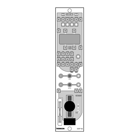
Chapitre 1 - Installation OCP 42/OCP 50 Description mécanique 1.2 - DESCRIPTION MÉCANIQUE POIDS : 1,2 KG environ DIMENSIONS : ON AIR 1 VIEW AIR 2 LOCK ACTIV CCU STATUS BARS SETTING CALL EXIT NEXT CTRL DIAG PRESET GAIN FILTERS... -
Page 14: Description Et Raccordement Des Connecteurs
Chapitre 1 - Installation OCP 42/OCP 50 Description et raccordement des connecteurs 1.3 - DESCRIPTION ET RACCORDEMENT DES CONNEC- TEURS 1.3.1 - Implantation et fonction des connecteurs Nota: La fonction des connecteurs de l’OCP 50 utilisé avec un MSP (système centralisé) est décrite dans le manuel d’utilisation du MCP. -
Page 15: Description Des Connecteurs
Chapitre 1 - Installation OCP 42/OCP 50 Description et raccordement des connecteurs 1.3.2 - Description des connecteurs Nota: La description des connecteurs de l’OCP 50 utilisé avec un MSP (système centralisé) est décrite dans le manuel d’utilisation du MCP. • Alimentation du pupitre ( 10,5 V à... -
Page 16: Alimentation
Chapitre 1 - Installation OCP 42/OCP 50 Description et raccordement des connecteurs " & GROUND GROUND Placer l’inverseur OUT A1 OUT B1 • Transmission des LOOP-150Ω sur la RETURN B1 LOOP données: position LOOP si un RETURN A1 GROUND Pupitre/Autre... - Page 17 Chapitre 1 - Installation OCP 42/OCP 50 Description et raccordement des connecteurs POWER DC IN AUX DATA (CCU DT500) Embases du pupitre PREVIEW/AUX POWER GND DC IN AUX DATA GND PREVIEW/AUX Figure 1 : Connection des différentes alimentations du pupitre...
-
Page 18: Commande Preview
Chapitre 1 - Installation OCP 42/OCP 50 Description et raccordement des connecteurs 1.3.4 - Commande PREVIEW Nota: Sur l’OCP 50 cette commande est inutilisée si le pupitre est connecté avec un MSP (système centralisé). 1.3.4.1 - Description La commande du voyant PREVIEW du pupitre venant du présélecteur peut être de type boucle ou tension. -
Page 19: Adaptation Avec Le Cablage Ocp Type 1542
Chapitre 1 - Installation OCP 42/OCP 50 Description et raccordement des connecteurs 1.3.4.2 - Adaptation avec le cablage OCP type 1542 La connection de l'embase PREVIEW de l'OCP42 sur un câblage réalisé pour un OCP type 1542, nécessite l'emploi d'un des câbles adaptateurs suivant : Les connecteurs sont représentés côté... -
Page 20: Raccordement Sur La Caméra
Chapitre 1 - Installation OCP 42/OCP 50 Raccordement sur la caméra 1.4 - RACCORDEMENT SUR LA CAMÉRA Connecter l'embase CCU du pupitre à la prise «Remote» située sur la caméra à l'aide du câble spécial véhiculant à la fois l'alimentation du pupitre (12 V) et la liaison RS422. -
Page 21: Raccordement Sur Un Ccu
Chapitre 1 - Installation OCP 42/OCP 50 Raccordement sur un CCU 1.5 - RACCORDEMENT SUR UN CCU Deux possibilités sont à envisager : 1. Le pupitre est seul à être connecté sur le contrôle de voie : •Connecter le câble d'alimentation entre l'embase DC IN du pupitre et l'embase RCP POWER OUT du contrôle de voie. -
Page 22: Affichage À La Mise Sous Tension
Chapitre 1 - Installation OCP 42/OCP 50 Affichage à la mise sous tension 1.6 - AFFICHAGE À LA MISE SOUS TENSION 1.6.1 - Page d'accueil Mettre l'équipement sous tension. La page d'accueil s'affiche. Cette page indique la version de logiciel équipant le pupitre :... -
Page 23: Chapitre 1 - Installation Ocp 42/Ocp 50 Configuration (Setting)
Chapitre 1 - Installation OCP 42/OCP 50 Configuration (SETTING) 1.7 - CONFIGURATION (SETTING) Nota: Ce paragraphe décrit les opérations à effectuer lors de l'installation d'un équipement. L'exploitation complète du pupitre est décrite dans le chapitre EXPLOITATION de ce manuel. 1.7.1 - Avertissement Les particularités de configuration des équipements avec un système centralisé... -
Page 24: Modification D'un Paramètre
Chapitre 1 - Installation OCP 42/OCP 50 Configuration (SETTING) 2. Modification d'un paramètre Après sélection de la configuration à modifier : • Appuyer sur la touche d'exploitation en regard du paramètre à modifier (le voyant situé sur la touche s'éclaire). -
Page 25: Configuration Du Pupitre
Chapitre 1 - Installation OCP 42/OCP 50 Configuration (SETTING) 1.7.3 - Configuration du pupitre Mettre l'équipement sous tension. La page d'accueil s'affiche. Après l'établissement de la liaison avec la caméra cette page est remplacée par la page de repos STATUS 1 (décrite dans le chapitre EXPLOITATION de ce manuel). - Page 26 Chapitre 1 - Installation OCP 42/OCP 50 Configuration (SETTING) • BEEPER (*) : Configuration de fonctionnement du témoin sonore situé à l'intérieur du pupitre : - OFF : Tous les messages sonores sont interdits. - WARNING : Un message sonore est émis lors d'une commande de l'opérateur, si celle ci n'est pas valide.
- Page 27 Chapitre 1 - Installation OCP 42/OCP 50 Configuration (SETTING) • BLACK POT(*): Affecte la fonction des réglages des commandes de noirs partiels: - FLARE: Les commandes de noirs partiels R, G, B sont affectés aux réglages de FLARE R, G, B. La page de repos value indique alors la valeur de réglage des FLARE R, G, B. Se référer au chapitre EXPLOITATION paragraphe: 2.6.3 - Page de repos VALUES.
- Page 28 Cette page permet : • CALIB MAX et CALIB MIN permettent d'effectuer la calibration du joystick (se référer au paragraphe 3.2.2 - Calibration de la commande d’IRIS (OCP 42)). • CONTRAST : Réglage du contraste de l'afficheur. • LED TEST : L'appui sur la touche allume pendant environ 3 secondes toutes les signalisations du pupitre (sauf "PREVIEW").
-
Page 29: La Page De Repos Custom
Chapitre 1 - Installation OCP 42/OCP 50 Configuration (SETTING) 1.7.3.1 - La page de repos CUSTOM La page de repos "CUSTOM" est une page permettant un accès rapide aux 4 principaux réglages d’exploitation les plus fréquemment utilisés. Pour affecter les réglages: •... -
Page 30: Configuration Du Contrôle De Voie
Chapitre 1 - Installation OCP 42/OCP 50 Configuration (SETTING) 1.7.4 - Configuration du contrôle de voie Mettre l'équipement sous tension. La page d'accueil s'affiche. Après l'établissement de la liaison avec la caméra cette page est remplacée par la page de repos STATUS 1 (décrite dans le chapitre EXPLOITATION paragraphe 2.6.1 - Page de repos... - Page 31 Chapitre 1 - Installation OCP 42/OCP 50 Configuration (SETTING) L'appui sur la touche NEXT affiche la 2ème page de configuration du contrôle de voie : 0 2 0) 5 - 5 + 2 0) 5 - " & Si le pupitre est connecté sur un EFP multiconducteurs, cette page permet de modifier les paramètres suivants :...
-
Page 32: Configuration De La Caméra
Chapitre 1 - Installation OCP 42/OCP 50 Configuration (SETTING) 1.7.5 - Configuration de la caméra Nota: La sélection d'un numéro pour la caméra connecté sur l'équipement est décrite dans le paragraphe: 1.7.3 - Configuration du pupitre. Mettre l'équipement sous tension. - Page 33 Chapitre 1 - Installation OCP 42/OCP 50 Configuration (SETTING) Au moyen de la commande ADJUST : • GAMMA LAW : Choix de la loi de GAMMA : - FACT : Loi FACTORY (sélection recommandée). - CUST : Loi CUSTOM. En standard la caméra est livrée avec une loi CUSTOM égale à la loi FACTORY.
- Page 34 Chapitre 1 - Installation OCP 42/OCP 50 Configuration (SETTING) • CAM CARD : Accès à la page permettant les transferts entre caméra et carte mémoire : R E CA L L S T OR E CAME RA CARD L'utilisation de la carte mémoire est décrite dans le paragraphe : 2.7 - Memory card / Touche MEMORY •...
- Page 35 Chapitre 1 - Installation OCP 42/OCP 50 Configuration (SETTING) L'appui simultané sur les 2 touches d'exploitation "YES" permet d'activer les menus techni- ques de la caméra. L'activation des menus techniques provoque l'affichage du texte sur TOUTES LES SORTIES VIDÉOS de l'équipement. La page suivante s'affiche : ←...
-
Page 36: Récapitulatif Des Différentes Pages De Configuration
Chapitre 1 - Installation OCP 42/OCP 50 Configuration (SETTING) 1.7.6 - Récapitulatif des différentes pages de configuration Mise sous tension Si la liaison OCP - Caméra ou T HOMSON OCP - CCU ne s’effectue pas OC P V e r s i o n X . X Après établissement liaison... -
Page 37: Configuration De La Commande Master Black (Ocp 42)
Chapitre 1 - Installation OCP 42/OCP 50 Configuration de la commande master black (OCP 42) 1.8 - CONFIGURATION DE LA COMMANDE MASTER BLACK (OCP 42) Le bouton de commande du MASTER BLACK est composé de deux parties pouvant être soli- daire ou non l'une de l'autre suivant l'exploitation retenue. - Page 38 Chapitre 1 - Installation OCP 42/OCP 50 Configuration de la commande master black (OCP 42) THOMSON OCP 42/OCP 50 B1500M24LA Manuel utilisateur Septembre 2000...
- Page 39 Chapitre 2 - Exploitation OCP 42/OCP 50 Chapitre 2 Exploitation OCP 42/OCP 50 2.1 - Généralités..............41 2.2 - Description des touches ..........43 2.2.1 - Touches d'exploitation............43 2.2.2 - Touches situées autour de l’afficheur ........43 2.2.3 - Touche NEXT ................43 2.2.4 - Touche EXIT................
- Page 40 Chapitre 2 - Exploitation OCP 42/OCP 50 2.2.8.12 - Touche SETTING ..............67 2.2.8.13 - Touche FINE ADJUST ............67 2.2.8.14 - Récapitulatif des différents domaines......... 68 2.2.9 - Touches programmables ............69 2.2.9.1 - Touches F1, F2, F3, F4 ............69 2.3 - Description des commandes linéaires ......
-
Page 41: Généralités
• Commandes de noir partiel R, G, B (utilisées également pour certains autres réglages). • Commande de réglage du MASTER PED (placée en extrémité du Joystick sur l’OCP 42). • Commande ADJUST affectée suivant la configuration aux modifications des différents paramètres. - Page 42 Chapitre 2 - Exploitation OCP 42/OCP 50 Généralités • La page du domaine sélectionné par une touche de domaine • Les pages de repos status • La page de repos valeurs • Les pages de configuration (SETTING) • La page d'accueil •...
-
Page 43: Exploitation Ocp 42/Ocp 50 Description Des Touches
Chapitre 2 - Exploitation OCP 42/OCP 50 Description des touches 2.2 - DESCRIPTION DES TOUCHES 2.2.1 - Touches d'exploitation Sauf spécification contraire, le voyant mentionné dans chaque description de touche est le voyant intégré à la touche. 2.2.2 - Touches situées... -
Page 44: Touches De Contrôle
Chapitre 2 - Exploitation OCP 42/OCP 50 Description des touches 2.2.7 - Touches de contrôle Sauf spécification contraire, le voyant mentionné dans chaque description de touche est le voyant intégré à la touche. Les touches d'exploitation mentionnées correspondent aux 4 touches encadrant l'afficheur. - Page 45 Chapitre 2 - Exploitation OCP 42/OCP 50 Description des touches 2.2.7.4 - Touche BARS Cette touche permet d'activer les différents signaux test. Le signal test disponible en sortie de l'équipement dépend dans certaines configurations de la sélection monitoring "PM" ON AIR 1 (se référer au "SETTING"...
-
Page 46: Touche Call
Chapitre 2 - Exploitation OCP 42/OCP 50 Description des touches 2.2.7.5 - Touche CALL L'appui sur la touche provoque un appel à destination du ON AIR 1 cadreur. VIEW AIR 2 Un appel en provenance du cadreur allume le voyant de la... -
Page 47: Touche Preset
Chapitre 2 - Exploitation OCP 42/OCP 50 Description des touches 2.2.7.7 - Touche PRESET La fonction "PRESET" permet généralement de posi- tionner à une valeur standard (définie en usine ou en main- tenance) différents paramètres d'exploitation. Il existe 2 types de PRESET : 1. - Page 48 Chapitre 2 - Exploitation OCP 42/OCP 50 Description des touches La 2ème page de "PRESET" étant affichée, l'appui sur la touche NEXT affiche la 3ème page de "PRESET" : S K I N 1 S K I N 2 ERAS E CARD...
-
Page 49: Touche Store
Chapitre 2 - Exploitation OCP 42/OCP 50 Description des touches 2.2.7.8 - Touche STORE La touche STORE possède deux fonctions : • Mémorisation des réglages d'exploitation du pupitre. • Mémorisation de configuration d'affichage (associée au touche F1, F2, F3, F4). -
Page 50: Mémorisation D'affichage
Chapitre 2 - Exploitation OCP 42/OCP 50 Description des touches 2.2.7.8.2 - Mémorisation d'affichage Cette fonction permet de rappeler instantanément une configuration d'affichage (particulièrement utile si un para- mètre est fréquemment modifié). Quatre mémoires sont disponibles. La touche STORE est associée aux touches programmables F1, F2, F3, F4. - Page 51 Chapitre 2 - Exploitation OCP 42/OCP 50 Description des touches • Le retour à la page de repos se fait après un temps définit dans la configuration du pupitre (se référer à la partie Installation de ce manuel) ou par appui sur la touche EXIT.
-
Page 52: Touches De Domaine
Chapitre 2 - Exploitation OCP 42/OCP 50 Description des touches 2.2.8 - Touches de domaine Les touches d'exploitation mentionnées correspondent aux 4 touches situées autour de l'afficheur. 2.2.8.1 - Présentation Ces touches permettent de sélectionner un domaine de réglage. • La sélection d'un domaine allume le voyant de la touche du domaine correspondant. - Page 53 Chapitre 2 - Exploitation OCP 42/OCP 50 Description des touches 2.2.8.2 - Touche GAIN Permet d'effectuer les réglages du domaine GAIN : ON AIR 1 GA I N U P VIEW AIR 2 X X d B LOCK ACTIV CCU STATUS...
- Page 54 Chapitre 2 - Exploitation OCP 42/OCP 50 Description des touches La première page du détail étant affichée, l'appui sur la touche NEXT affiche la 2ème page de réglage du détail : SO F T L E V E L D I A G D T L...
- Page 55 Chapitre 2 - Exploitation OCP 42/OCP 50 Description des touches Le voyant de la touche d'exploitation allumé indique la position actuelle du zoom WIDE ou TELE (elle n'est donc pas sélectable). La commande ADJUST permet de régler le niveau de détail correspondant à cette position.
- Page 56 Chapitre 2 - Exploitation OCP 42/OCP 50 Description des touches • Si par défaut les commandes des noirs partiels sont affectées aux réglages des FLARE: - BLACK R : Réglage du BLACK de la voie rouge par action sur la commande noir partiel rouge.
- Page 57 Chapitre 2 - Exploitation OCP 42/OCP 50 Description des touches 2.2.8.7 - Touche COLOUR Permet d'effectuer les réglages du domaine COLOUR. L'appui sur la touche affiche la page suivante : CO L . T EMP S A T URA T I ON X X X X °...
- Page 58 Chapitre 2 - Exploitation OCP 42/OCP 50 Description des touches 2.2.8.8 - Touche KNEE Permet d'effectuer les réglages du domaine KNEE. Ces réglages agissent sur le dispositif de compression du blanc permettant de restituer sur une dynamique réduite, les parties de l'image les plus fortement éclairées, tout en conservant la colorimétrie des zones compressées.
- Page 59 Chapitre 2 - Exploitation OCP 42/OCP 50 Description des touches 2.2.8.9 - Touche SHUTTER Permet d'effectuer les réglages du domaine SHUTTER. L'appui sur la touche affiche la page suivante : S HU T S P E E D C S S P E E D...
- Page 60 Chapitre 2 - Exploitation OCP 42/OCP 50 Description des touches 2.2.8.10 - Touche GAMMA Permet d'effectuer les réglages du domaine GAMMA. L'appui sur la touche affiche la 1ère page de réglage : GAMMA X . X X ON AIR 1...
-
Page 61: Skin1 : Par Appui Sur La Touche D'exploitation
Chapitre 2 - Exploitation OCP 42/OCP 50 Description des touches 2.2.8.11 - Touche SKIN Permet d'effectuer les réglages du domaine SKIN. La fonction SKIN permet d'associer un niveau de détail à une teinte déterminée de l'image. Deux teintes peuvent être mémorisées : SKIN1 et SKIN2. - Page 62 Chapitre 2 - Exploitation OCP 42/OCP 50 Description des touches Dans cette page : • SKIN IND : L'appui sur la touche d'exploitation correspondante : ON AIR 1 VIEW AIR 2 - Inscrit un rectangle d'acquisition dans le viseur. La...
-
Page 63: Récapitulatif Du Domaine Skin
Chapitre 2 - Exploitation OCP 42/OCP 50 Description des touches 2.2.8.11.1 - Récapitulatif du domaine SKIN S K I N 1 S K I N 2 O F F S K I N 1 AD J S K I N 2 AD J Vers réglages SKIN2... - Page 64 Chapitre 2 - Exploitation OCP 42/OCP 50 Description des touches • Appuyer sur la touche d'exploitation SKIN1 ADJ : S K I N 1 S K I N L V L SKI N I ND S K I N 1 D E T •...
-
Page 65: Appuyer Sur La Touche De Domaine Skin Du Pupitre Et Mettre En Fonction Le Skin1 (Skin1=On)
Chapitre 2 - Exploitation OCP 42/OCP 50 Description des touches • Appuyer sur la touche d'exploitation EXIT pour afficher à nouveau : S K I N 1 S K I N L V L SKI N I ND S K I N 1 D E T •... - Page 66 Chapitre 2 - Exploitation OCP 42/OCP 50 Description des touches • Appuyer sur la touche NEXT du pupitre pour afficher la page de réglages manuels : COLOUR R 1 CO L OUR B 1 ACCUR R 1 ACCUR B 1 •...
-
Page 67: Touche Setting
Chapitre 2 - Exploitation OCP 42/OCP 50 Description des touches 2.2.8.12 - Touche SETTING Permet d'effectuer les configurations du pupitre, du contrôle de voie, de la caméra. Ce domaine est décrit dans ON AIR 1 VIEW AIR 2 le chapitre INSTALLATION de ce manuel. -
Page 68: Récapitulatif Des Différents Domaines
Chapitre 2 - Exploitation OCP 42/OCP 50 Description des touches 2.2.8.14 - Récapitulatif des différents domaines SETTING Se référer au chapitre Installation D E T A I L KN E E SETTING SAT URA T I ON P E D E S T A L... -
Page 69: Touches Programmables
Chapitre 2 - Exploitation OCP 42/OCP 50 Description des touches 2.2.9 - Touches programmables 2.2.9.1 - Touches F1, F2, F3, F4 ON AIR 1 VIEW AIR 2 Permettent de mémoriser et de rappeler une configuration LOCK ACTIV CCU STATUS BARS... -
Page 70: Chapitre 2 - Exploitation Ocp 42/Ocp 50 Description Des Commandes Linéaires
Chapitre 2 - Exploitation OCP 42/OCP 50 Description des commandes linéaires 2.3 - DESCRIPTION DES COMMAN- DES LINÉAIRES NEXT CTRL DIAG ADJUST : Réglage de la valeur du paramètre affiché et PRESET GAIN FILTERS DETAIL sélectionné sur l'afficheur si le paramètre est à commande... -
Page 71: Chapitre 2 - Exploitation Ocp 42/Ocp 50 Description Des Voyants
Chapitre 2 - Exploitation OCP 42/OCP 50 Description des voyants 2.4 - DESCRIPTION DES VOYANTS ON AIR 2 : S'allume lorsque l'équipement est sur antenne secondaire. PREVIEW : S'allume lorsque la vidéo de l'équipement est sélectionnée sur les écrans de contrôle de la salle de... -
Page 72: Commandes Preview
Chapitre 2 - Exploitation OCP 42/OCP 50 Commandes PREVIEW 2.5 - COMMANDES PREVIEW (Uniquement sur OCP 42) Permettent de sélectionner la vidéo de l'équipement sur les écrans de contrôle de la salle de contrôle technique (via un EXTENDER préselecteur extérieur). Se référer au chapitre Installation, connecteur PREVIEW/AUX, de ce manuel. -
Page 73: Chapitre 2 - Exploitation Ocp 42/Ocp 50 Description Des Pages De Repos
Chapitre 2 - Exploitation OCP 42/OCP 50 Description des pages de repos 2.6 - DESCRIPTION DES PAGES DE REPOS Les pages de repos renseignent l'opérateur sur divers états d'exploitation de l'équipement. Elles s'affichent si aucun domaine n'est sélectionné. La page "CUSTOM" permet la modification de 4 réglages d’exploitation. -
Page 74: Page De Repos Status 1
Chapitre 2 - Exploitation OCP 42/OCP 50 Description des pages de repos 2.6.1 - Page de repos STATUS 1 Cette page s'affiche à la mise sous tension de l'équipement après l'affichage de la page d'accueil ou par appui sur la touche NEXT si la page affichée est la page de valeur. -
Page 75: Page De Repos Values
Chapitre 2 - Exploitation OCP 42/OCP 50 Description des pages de repos L'état suivant est affiché en permanence : • L'indication 2/2 signalant que la page affichée est la 2ème page de status. KN E E O F F AB L... -
Page 76: Page De Repos Custom
Chapitre 2 - Exploitation OCP 42/OCP 50 Description des pages de repos 2.6.4 - Page de repos CUSTOM Cette page s'affiche par appui sur la touche NEXT si la page "VALUES" est affichée. Les types de réglage affichés sont configurables (se référer au chapitre INSTALLATION para- graphe:1.7.3.1 - La page de repos CUSTOM). -
Page 77: Chapitre 2 - Exploitation Ocp 42/Ocp 50 Memory Card / Touche Memory
Chapitre 2 - Exploitation OCP 42/OCP 50 Memory card / Touche MEMORY 2.7 - MEMORY CARD / TOUCHE MEMORY 2.7.1 - Présentation La carte mémoire permet, suivant les configurations, la mémorisation des réglages d'exploita- tion ou techniques d'une ou plusieurs caméras. -
Page 78: Configurations D'exploitation
OCP 50 OCP 50 Remarque : L'OCP 42 peut être remplacé par l'OCP 50 : Seule la commande d'IRIS est différente. L'OCP 50 n'a pas de commande PREVIEW. Enregistrement et lecture des réglages techniques et d'exploitation de la caméra avec une carte de type "CAMERA". -
Page 79: Configurations Caméra Seule
OCP 42 OCP 42 OCP 42 Remarque : L'OCP 42 peut être remplacé par l'OCP 50 : Seule la commande d'IRIS est différente. Enregistrement et lecture des réglages techniques et d'exploitation de la caméra avec une carte de type "CAMÉRA". -
Page 80: Exploitation
4 "Scene Files" de toutes les caméras connectées sur le MCP. - Avec un OCP 42 : De sauvegarder dans la carte tous les réglages d'exploitation et les 4 "Scene Files" de la caméra connectée sur le CCU. Il est possible de mémoriser 24 caméras sur une carte. -
Page 81: Transfert "Carte Vers Studio
D'une façon générale, cette fonction permet de transférer les réglages d'exploitation d'une (OCP 42) ou plusieurs caméras (OCP 50+MSP) vers une ou plusieurs caméras. L' appui sur la touche MEMORY de l'OCP 42/OCP 50 affiche la page principale de transfert STUDIO :... -
Page 82: Transfert De "Caméra Vers Carte
"TFR TYPE" et "CARD FILE". - Avec un OCP 42 : De transférer dans la caméra connectée sur l'équipement les réglages indiqués et sélectionnés dans "TFR TYPE" et "CARD FILE" (la sélection "CARD FILE = STUDIO"... - Page 83 ABOR T WR I T E CARD Cette page permet : • CAM TYPE : Indication du type de caméra connectée sur l'équipement (OCP 42) ou sélectionnée sur le MSP (OCP 50). - D : Caméra digitale. • CARD FILE : Indication non modifiable.
-
Page 84: Transfert De "Carte Vers Caméra
• TFR TYPE : Sélection des réglages à transférer de la carte mémoire vers la caméra connectée sur l'équipement (OCP 42) ou sélectionnée sur le MSP (OCP 50). Le détail des réglages transférés est décrit dans le paragraphe 2.7.3 - Liste des réglages transférés en fonction de leur type. - Page 85 Chapitre 2 - Exploitation OCP 42/OCP 50 Memory card / Touche MEMORY transfert de la carte vers la caméra connectée sur l'équipement (OCP 42) ou sélectionnée sur le MSP (OCP 50) les réglages sélectionnés au moyen de TFR TYPE. Pendant l'écriture la page suivante s'affiche : WR I T I NG CAME RA P ROGR E S S .
-
Page 86: Liste Des Réglages Transférés En Fonction De Leur Type
Chapitre 2 - Exploitation OCP 42/OCP 50 Memory card / Touche MEMORY 2.7.3 - Liste des réglages transférés en fonction de leur type On distingue 6 types de réglages : OPERATION (OP), SF1 à SF4 (SF), LF1 ou LF2 (LF), MATCHING, TECHNIQUE. -
Page 87: Type Sf (Sf1 À Sf4)
Chapitre 2 - Exploitation OCP 42/OCP 50 Memory card / Touche MEMORY 2.7.3.2 - Type SF (SF1 à SF4) Un SCENE FILE est une mémoire permettant la sauvegarde des réglages d'exploitation. Il existe 4 SCENE FILES. Chaque SCENE FILE contient les réglages "OPERATION (OP)" listés précédemment (sauf ASPECT RATIO, CATCH IRIS, LENS FILE NUMBER, MASKING LAW, GAMMA LAW). -
Page 88: Type Technique (Tech)
Chapitre 2 - Exploitation OCP 42/OCP 50 Memory card / Touche MEMORY MASKING R>B CUST1 Technical Value MASKING R>G CUST1 Technical Value MASKING B>G CUST2 Technical Value MASKING B>R CUST2 Technical Value MASKING G>B CUST2 Technical Value MASKING G>R CUST2 Technical Value MASKING R>B CUST2... -
Page 89: Maintenance Ocp 42/Ocp 50
3.1 - Accès aux différents éléments ........91 3.1.1 - Dépose du capot.................. 91 3.1.2 - Dépose du mécanisme de monocommande (OCP 42) ....... 92 3.1.3 - Disposition des cartes et des connecteurs .......... 93 3.1.4 - Dépose des cartes................93 3.1.4.1 - Carte "MPU BOARD"............... - Page 90 Chapitre 3 - Maintenance OCP 42/OCP 50 THOMSON OCP 42/OCP 50 B1500M24LA Manuel utilisateur Septembre 2000...
-
Page 91: Accès Aux Différents Éléments
Chapitre 3 - Maintenance OCP 42/OCP 50 Accès aux différents éléments AVERTISSEMENT : TOUT COMPOSANT DOIT ÊTRE REMPLACÉ PAR UN COMPOSANT D'ORIGINE THOMSON BROADCAST SYSTEMS 3.1 - ACCÈS AUX DIFFÉRENTS ÉLÉMENTS 3.1.1 - Dépose du capot • Enlever les 6 vis de fixation du capot et la vis de fixation du mécanisme de monocommande. -
Page 92: Dépose Du Mécanisme De Monocommande (Ocp 42)
Vis de fixation du mécanisme de monocommande 3.1.2 - Dépose du mécanisme de monocommande (OCP 42) Déposer le capot. 1. Dépose du bouton de la monocommande - Enlever la bague de la partie inférieure du bouton. - Desserrer la vis situé dans la gorge. -
Page 93: Disposition Des Cartes Et Des Connecteurs
Chapitre 3 - Maintenance OCP 42/OCP 50 Accès aux différents éléments 3.1.3 - Disposition des cartes et des connecteurs MPU BOARD TOP KEYBOARD J110 DISPLAY BOTTOM KEYBOARD J111 MONOCONTROL MECHANISM 3.1.4 - Dépose des cartes Déposer le capot. 3.1.4.1 - Carte "MPU BOARD"... -
Page 94: Cartes "Top Keyboard" Et "Bottom Keyboard
Chapitre 3 - Maintenance OCP 42/OCP 50 Accès aux différents éléments Z120 Z110 Z100 Z130 Vis de fixation Z200 3.1.4.2 - Cartes "TOP KEYBOARD" et "BOTTOM KEYBOARD" • Déposer la carte "MPU BOARD". • Pour déposer la carte "TOP KEYBOARD" dévisser ses 2 entretoises de fixation. - Page 95 Chapitre 3 - Maintenance OCP 42/OCP 50 Accès aux différents éléments "TOP KEYBOARD" Entretoises de fixation J110 "BOTTOM KEYBOARD" Entretoises de fixation J111 B1500M24LA THOMSON OCP 42/OCP 50 Septembre 2000 Manuel utilisateur...
-
Page 96: Réglages
Chapitre 3 - Maintenance OCP 42/OCP 50 Réglages 3.2 - RÉGLAGES 3.2.1 - Contraste de l’afficheur • Appuyer sur la touche SETTING • Sélectionner le SETTING de l'OCP en appuyant sur la touche d'exploitation placée au dessus de l'affichage OCP. -
Page 97: Calibration De La Commande D'iris (Ocp 42)
Chapitre 3 - Maintenance OCP 42/OCP 50 Réglages 3.2.2 - Calibration de la commande d’IRIS (OCP 42) Cet automatisme permet de calibrer la commande d'iris. La calibration est à effectuer dans les cas suivant : • Suite à l'échange du mécanisme de monocommande. -
Page 98: Potentiomètre D'iris (Ocp 42)
Chapitre 3 - Maintenance OCP 42/OCP 50 Réglages 3.2.3 - Potentiomètre d'IRIS (OCP 42) Ce réglage est à effectuer si la calibration décrite au paragraphe 2.2 ne s'effectue pas correcte- ment. Réglage • Déposer le capot du pupitre en laissant toutes les connections en place. - Page 99 1.7.4 - Channel control unit setting up ........... 124 1.7.5 - Camera setting up ..............126 1.7.6 - Review of the various setting up pages ......130 1.8 - Master black control knob (OCP 42) ......131 B1500M24LA THOMSON OCP 42/OCP 50...
- Page 100 2.6.2 - STATUS 2 rest page.............. 168 2.6.3 - REST-VALUE page..............169 2.6.4 - REST-CUSTOM page ............170 2.7 - OCP 42/OCP 50 memory card & memory key... 171 2.7.1 - Introduction ................171 2.7.2 - Operation ................174 2.7.3 - Settings and values transferred, listed by type ....180 CHAPTER 3 OCP 42/OCP 50 MAINTENANCE............
- Page 101 SECTION 2 - English version 3.1.1 - Removing the cover ............. 185 3.1.2 - Removing the monocontrol mechanism (OCP 42).... 186 3.1.3 - Layout of boards and connectors........187 3.1.4 - Removing the boards............187 3.2 - Adjustments ..............190 3.2.1 - Display contrast..............
- Page 102 SECTION 2 - English version THOMSON OCP 42/OCP 50 B1500M24LA User manual September 2000...
- Page 103 1.7.4 - Channel control unit setting up ............124 1.7.5 - Camera setting up ................126 1.7.6 - Review of the various setting up pages ..........130 1.8 - Master black control knob (OCP 42) ........... 131 B1500M24LA THOMSON OCP 42/OCP 50...
- Page 104 Chapter 1 - OCP 42/OCP 50 Installation THOMSON OCP 42/OCP 50 B1500M24LA User manual September 2000...
-
Page 105: Cases Of Use (Operating Configurations)
Chapter 1 - OCP 42/OCP 50 Installation Cases of use (operating configurations) 1.1 - CASES OF USE (OPERATING CONFIGURATIONS) The operational control panel connects to the following items of equipment: OCP 42/50 TTV 1657D CAMERA + VTR: REMOTE OCP 42/50... - Page 106 Chapter 1 - OCP 42/OCP 50 Installation Cases of use (operating configurations) OCP 42/50 CCU 1685 CAMERA CCU 1686 REMOTE TTV 1557D + CCU 1685 OR 1686: OCP 40 / OCP 42 (STAND ALONE) OCP 42/50 CAMERA CCU DT500 TTV 1707 + CCU DT500...
-
Page 107: Mechanical Description
Chapter 1 - OCP 42/OCP 50 Installation Mechanical description 1.2 - MECHANICAL DESCRIPTION WEIGHT: 1.2 kg DIMENSIONS: ON AIR 1 VIEW AIR 2 LOCK ACTIV CCU STATUS BARS SETTING CALL EXIT NEXT CTRL DIAG PRESET GAIN FILTERS DETAIL STORE BLACK... -
Page 108: Description And Connection Of Connectors
Chapter 1 - OCP 42/OCP 50 Installation Description and connection of connectors 1.3 - DESCRIPTION AND CONNECTION OF CONNECTORS 1.3.1 - Connector locations and functions Note: The OCP 50 connector functions used with a MSP (centralized system) is described in the MCP user manual. -
Page 109: Description Of Connectors
Chapter 1 - OCP 42/OCP 50 Installation Description and connection of connectors 1.3.2 - Description of connectors Note: The OCP 50 description of connector used with a MSP (centralized system) is described in the MCP user manual. • DC supply input of between 10.5... -
Page 110: Power Supply
Chapter 1 - OCP 42/OCP 50 Installation Description and connection of connectors " & GROUND GROUND OUT A1 Ω OUT B1 Set LOOP/150 RETURN B1 • Data IN OUT LOOP switch to LOOP if a RETURN A1 GROUND OCP/Other panel. - Page 111 Chapter 1 - OCP 42/OCP 50 Installation Description and connection of connectors POWER DC IN AUX DATA (CCU DT500) OCP sockets PREVIEW/AUX POWER GND DC IN AUX DATA GND PREVIEW/AUX Figure 1 : Connection of the OCP power supplies B1500M24LA...
-
Page 112: Preview Control
Chapter 1 - OCP 42/OCP 50 Installation Description and connection of connectors 1.3.4 - PREVIEW control Note: On the OCP 50 , this control is not used if the panel is used with a MSP (centralized system). 1.3.4.1 - Description The OCP PREVIEW light control from the preselector may be of the loop or voltage type. -
Page 113: Adaptation To Type 1542 Ocp Wiring
Chapter 1 - OCP 42/OCP 50 Installation Description and connection of connectors 1.3.4.2 - Adaptation to type 1542 OCP wiring Connection of the PREVIEW socket of the OCP 40 to a cable assembly produced for type 1542 OCP calls for the use of one of the following adapter cables: The wiring sides of the connectors are shown. -
Page 114: Connection To Camera
Chapter 1 - OCP 42/OCP 50 Installation Connection to camera 1.4 - CONNECTION TO CAMERA Connect the panel CCU socket to the «Remote» connector on the camera using the special cable carrying the panel power supply (12 V) and the RS422 link simultaneously. -
Page 115: Connection To A Ccu
Chapter 1 - OCP 42/OCP 50 Installation Connection to a CCU 1.5 - CONNECTION TO A CCU There are two possibilities: 1. The OCP alone is connected to the Channel Control Unit: - Connect the power supply cable between the DC IN socket on the panel and the RCP POWER OUT socket on the Channel Control Unit. -
Page 116: Display On Power On
Chapter 1 - OCP 42/OCP 50 Installation Display on POWER ON 1.6 - DISPLAY ON POWER ON 1.6.1 - Welcome page Switch on the equipment. The welcome page is displayed. This page indicates the panel software version: T HOMSON OC P V e r s i o n X . -
Page 117: Setting Up
Chapter 1 - OCP 42/OCP 50 Installation Setting up 1.7 - SETTING UP Note: This paragraph describes the operations to be performed when installing an equipment. Complete operational use of the panel is described in the OPERATING INSTRUCTIONS chapter of this manual. -
Page 118: Parameter Modification
Chapter 1 - OCP 42/OCP 50 Installation Setting up 2. Parameter modification After selection of the configuration to be modified: • Press the button above or below the parameters to be modified (the button indicator light lights). • Actuate the ADJUST control to modify the parameter value. -
Page 119: Setting Up The Ocp
Chapter 1 - OCP 42/OCP 50 Installation Setting up 1.7.3 - Setting up the OCP Switch on the equipment. The welcome page is displayed. After making the connection with the camera, this page is replaced by the STATUS 1 rest page (described in the OPERATING INSTRUCTIONS chapter of this manual). - Page 120 Chapter 1 - OCP 42/OCP 50 Installation Setting up - WARNING: An audible message is emitted on an operator command, if the command is not valid. - ALL EVENTS: An audible message is emitted when one of the panel buttons is pressed, or if an operator command is not valid.
- Page 121 Chapter 1 - OCP 42/OCP 50 Installation Setting up REST-VALUE page 2.6.3 - paragraph. (*) These commandes are memorized when the «EXIT» button is pressed (exit from set- ting up menu). Press NEXT to display the third panel setting up page:...
- Page 122 Chapter 1 - OCP 42/OCP 50 Installation Setting up purposes.Refer to the MAINTENANCE chapter, 3.2.2 - Calibration of iris control (OCP 42) paragraph. • CONTRAST: Display contrast adjustment. • LED TEST: Pressing this button light all the OCP leds (except "PREVIEW) during 3 seconds.
-
Page 123: The Custom Rest Page
Chapter 1 - OCP 42/OCP 50 Installation Setting up 1.7.3.1 - The CUSTOM rest page The CUSTOM rest page permits a fast access to the 4 frequently used operating adjustments. Choice of the adjustments: • Display the second panel setting uo page and press the CUST PAGE button. -
Page 124: Channel Control Unit Setting Up
Chapter 1 - OCP 42/OCP 50 Installation Setting up 1.7.4 - Channel control unit setting up Switch on the equipment. The welcome page is displayed. After making the connection with the camera, this page is replaced by the STATUS 1 rest page (described in the OPERATING INSTRUCTIONS chapter, 2.6.1 - STATUS 1 rest page para-... - Page 125 Chapter 1 - OCP 42/OCP 50 Installation Setting up Pressing of the NEXT button displays the 2nd Channel Control Unit setting up page. 0 2 0) 5 - 5 + 2 0) 5 - " & If the panel is connected to a multiconductor EFP, this page is used to modify the following parameters: •...
-
Page 126: Camera Setting Up
Chapter 1 - OCP 42/OCP 50 Installation Setting up 1.7.5 - Camera setting up Note: The assigning camera number to the CCU camera connected is described in the paragraph: 1.7.3 - Setting up the OCP. Switch on the equipment. The welcome page is displayed. - Page 127 Chapter 1 - OCP 42/OCP 50 Installation Setting up Using the ADJUST control: • GAMMA LAW: Gamma law selection: - FACT: FACTORY law (recommended selection). - CUST: CUSTOM law. The standard camera is delivred with the CUSTOM law equal to the FACTORY law.
- Page 128 R E CA L L S T OR E CAME RA CARD For the memory card use description, refer to the paragraph: 2.7 - OCP 42/OCP 50 memory card & memory key • MENU: Display the camera technical menus call page.
- Page 129 Chapter 1 - OCP 42/OCP 50 Installation Setting up The next page displays ← ↑ ↓ → Access to the various technical adjustments is made in the same manner with the internal keyboard inside the lefthand side of the camera.
-
Page 130: Review Of The Various Setting Up
Chapter 1 - OCP 42/OCP 50 Installation Setting up 1.7.6 - Review of the various setting up pages Power ON If OCP - Caméra or OCP - T HOMSON CCU link is no made OC P V e r s i o n X . X After making OCP - Caméra link... -
Page 131: Master Black Control Knob (Ocp 42)
Chapter 1 - OCP 42/OCP 50 Installation Master black control knob (OCP 42) 1.8 - MASTER BLACK CONTROL KNOB (OCP 42) The MASTER BLACK control knob consists of two parts which, depending on the mode used, may be coupled to each other or not. If both parts are not coupled, MASTER BLACK is adjusted by the bottom part of the knob. - Page 132 Chapter 1 - OCP 42/OCP 50 Installation Master black control knob (OCP 42) THOMSON OCP 42/OCP 50 B1500M24LA User manual September 2000...
- Page 133 Chapter 2 - OCP 42/OCP 50 Operating Instructions Chapter 2 OCP 42/OCP 50 Operating Instructions 2.1 - General ................. 135 2.2 - Description of pushbuttons ........137 2.2.1 - Operational pushbuttons ............137 2.2.2 - Buttons located around the display ........137 2.2.3 - NEXT button................
- Page 134 2.6.2 - STATUS 2 rest page.............. 168 2.6.3 - REST-VALUE page..............169 2.6.4 - REST-CUSTOM page ............170 2.7 - OCP 42/OCP 50 memory card & memory key... 171 2.7.1 - Introduction ................171 2.7.1.1 - Inserting the memory card ........... 171 2.7.1.2 - Types of memory card ............
-
Page 135: General
• IRIS setting control. • R, G, B partial black controls (also used for other adjustments). • MASTER PED control (located on end of joystick OCP 40/OCP 42). • ADJUST control, assigned according to the settings to modification of different parameters. - Page 136 Chapter 2 -OCP 42/OCP 50 Operating Instructions General • The welcome page. • The WARNING page. Note: The SETTING, WARNING and welcome pages are described in the installation part of this manual. 5. A JOYSTICK (OCP 42) The joystick controls the IRIS and the MASTER PED.
-
Page 137: Description Of Pushbuttons
Chapter 2 - OCP 42/OCP 50 Operating Instructions Description of pushbuttons 2.2 - DESCRIPTION PUSHBUT- TONS 2.2.1 - Operational pushbuttons Unless otherwise specified, the indicator light mentioned in each button description is built into the button. 2.2.2 - Buttons located... -
Page 138: Control Buttons
Chapter 2 -OCP 42/OCP 50 Operating Instructions Description of pushbuttons 2.2.7 - Control buttons Unless otherwise stated, the indicator light mentioned in each button description is built into the button. The operation pushbuttons mentioned correspond to the 4 buttons around the display. - Page 139 Chapter 2 - OCP 42/OCP 50 Operating Instructions Description of pushbuttons 2.2.7.4 - BARS button This button activates the various test signals. The test signal available at the equipment output depends on some of the «PM» monitoring settings (see CCU «SETTING ON AIR 1 UP»...
-
Page 140: Call Button
Chapter 2 -OCP 42/OCP 50 Operating Instructions Description of pushbuttons 2.2.7.5 - CALL button Pressing this button calls the cameraman. ON AIR 1 A call from the cameraman lights the button indicator light. VIEW AIR 2 Pressing of the button while the indicator light is lit extin-... -
Page 141: Preset Button
Chapter 2 - OCP 42/OCP 50 Operating Instructions Description of pushbuttons 2.2.7.7 - PRESET button The «PRESET» button is generally used to position the various operating parameters to a standard value (works or maintenance defined). There are 2 types of PRESET: 1. - Page 142 CARD into a STUDIO CARD and vice versa. For the memory card use description, refer to the paragraph 2.7 - OCP 42/OCP 50 memory card & memory key. With the 3rd «PRESET» page displayed, pressing of NEXT displays the 4th «Preset» page.
- Page 143 Chapter 2 - OCP 42/OCP 50 Operating Instructions Description of pushbuttons 2.2.7.8 - STORE button The STORE button has two functions: • Storage of panel operational settings • Storage of display configuration (associated with buttons F1, F2, F3 and F4).
- Page 144 Chapter 2 -OCP 42/OCP 50 Operating Instructions Description of pushbuttons 2.2.7.8.2 - Display configuration storage This function is used to instantaneously recall a setting (particularly useful if a parameter is to be modified frequently). Four memories are available. The STORE button is asso- ciated with programmable buttons F1, F2, F3 and F4.
- Page 145 Chapter 2 - OCP 42/OCP 50 Operating Instructions Description of pushbuttons • Return to the rest page is made after a period defined in the panel settings (refer to the Installation part of this manual) or by pressing the EXIT button.
-
Page 146: Range Buttons
Chapter 2 -OCP 42/OCP 50 Operating Instructions Description of pushbuttons 2.2.8 - RANGE buttons The range buttons mentioned correspond to 4 buttons located around the display. 2.2.8.1 - Presentation These buttons are used to select a setting range. • Selection of a range lights the corresponding range light. - Page 147 Chapter 2 - OCP 42/OCP 50 Operating Instructions Description of pushbuttons 2.2.8.2 - GAIN button Used to adjust the GAIN range settings. Press the button to display the page below: GA I N U P X X d B GAI N DOWN By pressing the GAIN UP or GAIN DOWN buttons, the camera gain is increased or decreased.
- Page 148 Chapter 2 -OCP 42/OCP 50 Operating Instructions Description of pushbuttons With the first detail page displayed, press NEXT to display the 2nd detail setting page: SO F T L E V E L D I A G D T L...
- Page 149 Chapter 2 - OCP 42/OCP 50 Operating Instructions Description of pushbuttons This page can be used to alter the following parameters: • DFZ WIDE: Adjustment of detail level for the zoom wide angle position. • DFZ TELE: Adjustment of detail level for the zoom telelens position.
- Page 150 Chapter 2 -OCP 42/OCP 50 Operating Instructions Description of pushbuttons • If the partial black control ara assigned to FLARE adjustments - BLACK R: Red channel black adjustment by varying the red partial black control. - BLACK G: Green channel black adjustment by varying the green partial black control.
- Page 151 Chapter 2 - OCP 42/OCP 50 Operating Instructions Description of pushbuttons 2.2.8.7 - COLOUR button Used to perform COLOUR range adjustments. Press the button to display the page below: CO L . T EMP S A T URA T I ON X X X X °...
- Page 152 Chapter 2 -OCP 42/OCP 50 Operating Instructions Description of pushbuttons 2.2.8.8 - KNEE button Used to make KNEE range adjustments. These adjustments concern the white compression (knee) device used to restore the most strongly illuminated parts of the image over a low dynamic while conserving the colori- metry of the compressed areas.
- Page 153 Chapter 2 - OCP 42/OCP 50 Operating Instructions Description of pushbuttons 2.2.8.9 - SHUTTER button Used to adjust the SHUTTER range. Press this button to display the following page: S HU T S P E E D C S S P E E D...
- Page 154 Chapter 2 -OCP 42/OCP 50 Operating Instructions Description of pushbuttons 2.2.8.10 - GAMMA button Used to make GAMMA range adjustments. Press the button to display the 1st setting page: GAMMA X . X X ON AIR 1 VIEW AIR 2...
- Page 155 Chapter 2 - OCP 42/OCP 50 Operating Instructions Description of pushbuttons 2.2.8.11 - SKIN button Used to make SKIN range adjustments. The SKIN function is used to associate a detail level with a given colour of the image. Two colours can be stored, SKIN 1 and SKIN 2. The same detail level is applied to both colours.
- Page 156 Chapter 2 -OCP 42/OCP 50 Operating Instructions Description of pushbuttons In this page: • SKIN IND: Operation of the button under SKIN 1 IND: - Displays on the viewfinder an acquisition rectangle. ON AIR 1 VIEW AIR 2 The colour within the rectangle will be the reference...
- Page 157 Chapter 2 - OCP 42/OCP 50 Operating Instructions Description of pushbuttons 2.2.8.11.1 - SKIN RANGE review S K I N 1 S K I N 2 O F F S K I N 1 AD J S K I N 2 AD J...
- Page 158 Chapter 2 -OCP 42/OCP 50 Operating Instructions Description of pushbuttons • Press the SKIN 1 ADJ button: S K I N 1 S K I N L V L SKI N I ND S K I N 1 D E T •...
- Page 159 Chapter 2 - OCP 42/OCP 50 Operating Instructions Description of pushbuttons • Press the EXIT button to display the following page again: S K I N 1 S K I N L V L SKI N I ND S K I N 1 D E T •...
- Page 160 Chapter 2 -OCP 42/OCP 50 Operating Instructions Description of pushbuttons • Press NEXT on the panel to display the manual setting page: COLOUR R 1 CO L OUR B 1 ACCUR R 1 ACCUR B 1 • Using the R and B partial gain adjustments, adjust COLOUR R1 and COLOUR B1 to display the area to which the SKIN function is to be applied in colour.
-
Page 161: Setting Button
Chapter 2 - OCP 42/OCP 50 Operating Instructions Description of pushbuttons 2.2.8.12 - SETTING button Used to set up the OCP, the Channel Control Unit and the camera. This range is described in the INSTALLATION ON AIR 1 VIEW AIR 2 chapter. -
Page 162: Review Of The Various Ranges
Chapter 2 -OCP 42/OCP 50 Operating Instructions Description of pushbuttons 2.2.8.14 - Review of the various ranges SETTING - Refer to chapter Installation. D E T A I L KN E E SETTING SAT URA T I ON P E D E S T A L... -
Page 163: Programming Buttons
Chapter 2 - OCP 42/OCP 50 Operating Instructions Description of pushbuttons 2.2.9 - Programming buttons 2.2.9.1 - Buttons F1, F2, F3 and F4 ON AIR 1 VIEW AIR 2 Used to store and recall a display configuration (particu- LOCK ACTIV CCU STATUS... -
Page 164: Description Of Linear Controls
Chapter 2 -OCP 42/OCP 50 Operating Instructions Description of linear controls 2.3 - DESCRIPTION OF LINEAR CON- TROLS NEXT CTRL DIAG ADJUST: Adjusts the value of the parameter displayed PRESET GAIN FILTERS DETAIL and, on the display, selects whether the control is gradual... -
Page 165: Description Of Indicator Lights
Chapter 2 - OCP 42/OCP 50 Operating Instructions Description of indicator lights 2.4 - DESCRIPTION OF INDICATOR LIGHTS ON AIR 2: Lights when the equipment is on the secondary antenna. PREVIEW: Lights when the equipment video is selected ON AIR 1... -
Page 166: Preview Controls
Chapter 2 -OCP 42/OCP 50 Operating Instructions Preview controls 2.5 - PREVIEW CONTROLS Only OCP 42 is fitted with PREVIEW controls. Used to select the equipment video on the technical control room screens (via an external preselector). Refer to EXTENDER connector PREVIEW/AUX of the Installation chapter of this manual. -
Page 167: Description Of Rest
Chapter 2 - OCP 42/OCP 50 Operating Instructions Description of rest pages 2.6 - DESCRIPTION OF REST PAGES The rest pages inform the operator of the various operational states of the equipment. These are displayed if there is no range selected. The rest CUSTOM page permit the modification of 4 operating adjustments. -
Page 168: Status 1 Rest Page
Chapter 2 -OCP 42/OCP 50 Operating Instructions Description of rest pages 2.6.1 - STATUS 1 rest page On switching on of the equipment after display of the welcome page, or when NEXT is displayed if the displayed page is the value page, this page is displayed. -
Page 169: Rest-Value Page
Chapter 2 - OCP 42/OCP 50 Operating Instructions Description of rest pages The following status is permanently displayed: • Indication 2/2 indicates that the page displayed is the 2nd status page. KN E E O F F AB L KN E E AU T OHO L D D F Z GAMMA X . -
Page 170: Rest-Custom Page
Chapter 2 -OCP 42/OCP 50 Operating Instructions Description of rest pages 2.6.4 - REST-CUSTOM page By pressing the NEXT key, this page is displayed if the VALUES page is displayed. The adjustment types displayed are configurable. Refer to the INSTALLATION chapter, 1.7.3.1 - The CUSTOM rest page paragraph. -
Page 171: Ocp 42/Ocp 50 Memory Card & Memory Key
2.7 - OCP 42/OCP 50 MEMORY CARD & MEMORY KEY 2.7.1 - Introduction On the OCP 42 and OCP 50, the memory card is used to store operating settings or technical values (depending on the configuration) for one or more cameras. -
Page 172: Operating Configurations
OCP 50 OCP 50 Note: The OCP 42 may be replaced by the OCP 50: only the IRIS control is different. The OCP50 is not fitted of PREVIEW control. Record and read the camera’s technical values and operating settings with a ‘CAMERA’... -
Page 173: Configuring A Camera Only
OCP 42 OCP 42 Note: The OCP 42 may be replaced by the OCP 50: only the IRIS control is different. The OCP50 is not fitted of PREVIEW control. Record and read the camera’s technical values and operating settings with a ‘CAMERA’... -
Page 174: Operation
MCP. - With an OCP 42: saves on the card all the operating settings and the 4 ‘Scene Files’ for the camera connected to the CCU. The settings for up to 24 cameras can be stored on one card. -
Page 175: Card To Studio' Transfer
In general terms, this function is used to read the operating settings for a set of cameras (OCP50+MSP) or for a camera (OCP 42) from the card and to transfer them to a set of cameras or for a camera. -
Page 176: Camera To Card' Transfer
- With an OCP 50: transfers the settings indicated and selected in ‘TFR TYPE’ and ‘CARD FILE’ to the camera(s) selected using the MSP. - With an OCP 42: transfers the settings indicated and selected in ‘TFR TYPE’ and ‘CARD FILE’ to the camera connected to the equipment (the selection ‘CARD FILE = STUDIO’... - Page 177 ABOR T WR I T E CARD The following functions are available on this page: • CAM TYPE: indicates the type of camera connected to the equipment (OCP 42) or selected on the MSP (OCP 50). - D: digital camera.
-
Page 178: Card To Camera' Transfer
The following functions are available on this page: • TFR TYPE: selects the settings to be transferred from the card to the camera connected to the equipment (OCP 42) or selected on the MSP (OCP 50). Paragraph 3 describes in detail the settings transferred. - Page 179 OCP 42/OCP 50 memory card & memory key settings selected using TFR TYPE from the card to the camera connected to the equipment (OCP 42) or to the camera selected on the MSP (OCP 50). During the writing, the following page displays: WR I T I NG CAME RA P ROGR E S S .
-
Page 180: Settings And Values Transferred, Listed By Type
Chapter 2 -OCP 42/OCP 50 Operating Instructions OCP 42/OCP 50 memory card & memory key 2.7.3 - Settings and values transferred, listed by type There are 6 types of settings: OPERATION (OP), SF1 to SF4 (SF), LF1 or LF2, MATCHING, and TECHNICAL 2.7.3.1 - OPERATION type (OP) -
Page 181: Sf Type (Sf1 To Sf4)
Chapter 2 - OCP 42/OCP 50 Operating Instructions OCP 42/OCP 50 memory card & memory key 2.7.3.2 - SF Type (SF1 TO SF4) A SCENE FILE is a memory used to store operating settings. There are 4 scene files. Each scene file contains the OPERATION (OP) settings listed above (except for ASPECT RATIO, CATCH IRIS, LENS FILE NUMBER, MASKING LAW and GAMMA LAW). -
Page 182: Technical Type (Tech)
Chapter 2 -OCP 42/OCP 50 Operating Instructions OCP 42/OCP 50 memory card & memory key MASKING B>G CUST2 Technical Value MASKING B>R CUST2 Technical Value MASKING G>B CUST2 Technical Value MASKING G>R CUST2 Technical Value MASKING R>B CUST2 Technical Value MASKING R>G CUST2... -
Page 183: Ocp 42/Ocp 50 Maintenance
3.1 - Access to the various units ........185 3.1.1 - Removing the cover................185 3.1.2 - Removing the monocontrol mechanism (OCP 42) ......186 3.1.3 - Layout of boards and connectors ............187 3.1.4 - Removing the boards................. 187 3.1.4.1 - MPU board.................. - Page 184 Chapter 3 - OCP 42/OCP 50 Maintenance THOMSON OCP 42/OCP 50 B1500M24LA User manual September 2000...
-
Page 185: Access To The Various Units
Chapter 3 - OCP 42/OCP 50 Maintenance Access to the various units WARNING ALL COMPONENTS MUST BE REPLACED BY THOMSON BROADCAST SYSTEMS ORIGINAL COMPONENTS 3.1 - ACCESS TO THE VARIOUS UNITS 3.1.1 - Removing the cover • Loosen the 6 cover attaching screws and the monocontrol mechanism attaching screw. -
Page 186: Removing The Monocontrol Mechanism (Ocp 42)
3 side attaching screws Monocontrol mechanism attaching screw 3.1.2 - Removing the monocontrol mechanism (OCP 42) Remove the cover. 1. Removing the monocontrol knob • Remove the ring from the bottom part of the knob. • Loosen the screw in the groove. -
Page 187: Layout Of Boards And Connectors
Chapter 3 - OCP 42/OCP 50 Maintenance Access to the various units 3.1.3 - Layout of boards and connectors MPU BOARD TOP KEYBOARD J110 DISPLAY BOTTOM KEYBOARD J111 MONOCONTROL MECHANISM 3.1.4 - Removing the boards Remove the cover. 3.1.4.1 - MPU board •... -
Page 188: Top Keyboard And Bottom Keyboard Boards
Chapter 3 - OCP 42/OCP 50 Maintenance Access to the various units Z120 Z110 Z100 Z130 Screws Z200 3.1.4.2 - TOP KEYBOARD and BOTTOM KEYBOARD boards • Remove the MPU BOARD. • To remove the TOP KEYBOARD, unscrew both Hexagonal pillars. - Page 189 Chapter 3 - OCP 42/OCP 50 Maintenance Access to the various units "TOP KEYBOARD" Hexagonal pillars J110 "BOTTOM KEYBOARD" Hexagonal pillars J111 B1500M24LA THOMSON OCP 42/OCP 50 September 2000 User manual...
-
Page 190: Adjustments
Chapter 3 - OCP 42/OCP 50 Maintenance Adjustments 3.2 - ADJUSTMENTS 3.2.1 - Display contrast • Press the "SETTING" button. • Select OCP "SETTING". • Select "CONTRAST" adjustment (press twice the "NEXT" button). CA L I B MA X CON T RA S T... -
Page 191: Calibration Of Iris Control (Ocp 42)
Chapter 3 - OCP 42/OCP 50 Maintenance Adjustments 3.2.2 - Calibration of iris control (OCP 42) This automated circuit is used to calibrate the iris control. Calibration is performed in the following cases: • Subsequent to replacement of the monocontrol mechanism. -
Page 192: Iris Potentiometer (Ocp 42)
Chapter 3 - OCP 42/OCP 50 Maintenance Adjustments 3.2.3 - IRIS potentiometer (OCP 42) This adjustment is to be made if the calibration operation described in paragraph 2.2 has not taken place correctly. Adjustment • Remove the panel cover, leaving all the connections in place.