Table des Matières
Publicité
Les langues disponibles
Les langues disponibles
Liens rapides
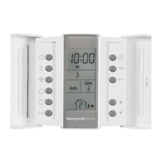
FP134 Pilot-wire Programmer
Installation and User Guide (EN)
FP134 is an electronic six-order pilot-wire programmer that allows separate
temperature control of three zones using four programs per day. The FP134
programmer has three pilot-wire outputs can be connected to thermostats
or controller that accept pilot-wire signals.
The FP134 programmer has a remote input to which a telephone controller,
a home automation system (HAS) or an energy manager can be connected.
When a signal is received from any of these devices, FP134 forwards the
order to the heating units.
Display
1 Time
2 Heating modes
1
2
3
4
3 Operating modes
4 Zone selected (the letter A appears
5
5 Current program (applicable to
Connections
Energy
OR
Manager
(Optional)
(Optional)
The following table shows the different means of initiating an order.
1.3
Connect the remote input (optional)
Telephone controller or Home automation system
Connect to terminals L and TEL of the programmer respectively.
NOTE: For details on wiring and operating the telephone controller or home
automation system, refer to the instruction manual of particular models.
Energy Manager
Connect the pilot wire output of the energy manager to the TEL input
of the programmer.
1.4
Complete the installation
1 Fix the mounting plate to the wall.
2 Install the faceplate on the
mounting plate and lock
them together using
the locking screw.
1.5
Apply power to the programmer
R
: Comfort mode
ƒ
: Setback modes
(icon is steady in 3,5k setback;
flashes in 1k and 2k setbacks)
T
: Frost protection
: Off
- Manual mode
- Auto mode
when all 3 zones are selected)
automatic mode only)
Telephone controller/Home
automation system (optional)
1
2
3
1 Order buttons
2 Mode selection button
3 Zone selection button
4 Time/day setting button
FP134
Energy
Telephone
buttons
manager
controller/HAS
R
ü
ü
ƒ
T
ü
ü
ü
ü
Installation
1
Must be installed by a competent person. To ensure your safety, make sure
the mains power is switched OFF before accessing wiring. The programmer
must be installed on an electrical box.
1.1
Remove the faceplate
1 Loosen the locking screw (the screw is
captive and cannot be completely removed).
2 Pull and lift the bottom of the faceplate to
remove it from its mounting plate.
1.2
Connect the programmer
Connect power to terminals L (line) and N (neutral).
Connect the pilot wire inputs of the thermostats to
terminals FP1, FP2 and FP3.
Power-up
2
During power-up, the
All three zones
are in comfort
FP134 perform a series
mode.
of test for approximately
5 seconds. Afterwards,
the programmer displays
The programmer is
the following:
in manual mode.
Time and day setting
1 Press
. The hours display flashes.
2 Set the hours using the pq buttons.
3 Press
. The minutes display flashes.
4 Set the minutes using the pq buttons.
5 Press
. The day display flashes.
6 Set the day using the pq buttons.
8
7 Press
to exit the time and day settings
4
5
6
7
5 Program button
6 Return button
7 Selection button
8 Display
Pilot wire order
Signals
Maintain temperature
No signal
at setpoint (Comfort)
Maintain temperature
at setpoint minus 3,5°C
(3,5k setback)
Maintain temperature
at 7°C (frost protection)
Turn heating Off (Off)
Maintain temperature
at setpoint minus 1°C
(1k setback)
Maintain temperature
at setpoint minus 2°C
(2k setback)
Flashes to indicate
that the time and day
must be set.
Zone 1 is selected.
Publicité
Table des Matières

Sommaire des Matières pour Honeywell Home FP134
- Page 1 (HAS) or an energy manager can be connected. 2 Mode selection button 6 Return button When a signal is received from any of these devices, FP134 forwards the 3 Zone selection button 7 Selection button order to the heating units.
-
Page 2: Manual Mode
• 0 (no program is selected for that day) 5 Select the mode by pressing the corresponding button. NOTE: If no program is selected for a particular day, FP134 uses the order of the last progarm until the start of the next program 6 Repeat steps 3 to 5 for the remaining programs for the selected zone. -
Page 3: Séparer La Façade Du Socle
1 Boutons de mode de chauffage 5 Bouton de programmation le FP134 est muni d’une entrée « TEL » à laquelle peut se raccorder une télécommande téléphonique, un système de domotique ou encore un 2 Mode de fonctionnement 6 Bouton Retour gestionnaire d’énergie. -
Page 4: Utilisation
This product manufactured by Resideo and its affiliates. Entrée à distance : Relais universel (230 VCA / 500 μA) ou fil pilote Pour de l’aide, visitez notre page internet The Honeywell Home trademark is used under license livewell.honeywellhome.com Section des fils électriques : 0,32 - 2,1 mm from Honeywell International Inc. -
Page 5: Conexión De La Entrada Remota (Opcional)
2 Botón de selección del modo de 6 Botón de aceptar El programador FP134 tiene una entrada remota a la que se puede conectar un funcionamiento 7 Botón de selección controlador por teléfono, un sistema de domótica (HAS) o un gestor de energía. -
Page 6: Modo Manual
NOTA: Si no se selecciona ningún programa para un día en concreto, el 5 Seleccione el modo pulsando el botón correspondiente. FP134 utiliza la orden del último programa hasta el comienzo del programa 6 Repita los pasos del 3 al 5 con los programas restantes para la zona siguiente seleccionada.


