Publicité
Les langues disponibles
Les langues disponibles
Liens rapides
Publicité

Manuels Connexes pour Scodif REC 80 M

Sommaire des Matières pour Scodif REC 80 M
- Page 1 Notice d’installation Manual Versions disponibles : froide Available versions: cold 21122011...
- Page 3 RECOMMANDATIONS PAGE 4 PAGE 4 - TRANSPORT - STOCKAGE DES FONTAINES PAGE 4 - UTILISATION PAGE 4 PAGE 5 DONNEES TECHNIQUES EQUIPEMENT / IDENTIFICATION PAGE 6 CLAVIERS DE COMMANDE ET FONCTIONS PAGE 7 INSTALLATION PAGE 8 à 10 - POUR TOUTES LES VERSIONS PAGE 8 à...
- Page 4 Lire attentivement toutes les instructions et les conserver pour s’y référer plus tard. Pour votre sécurité, débrancher la fontaine de son alimentation électrique afin d’éviter les risques de blessures ou de choc électrique lors d’une intervention sur celle-ci. Ne pas introduire d’objets métalliques, ni vos doigts dans l’appareil pour ne pas l’endommager et éviter tout risque de choc électrique.
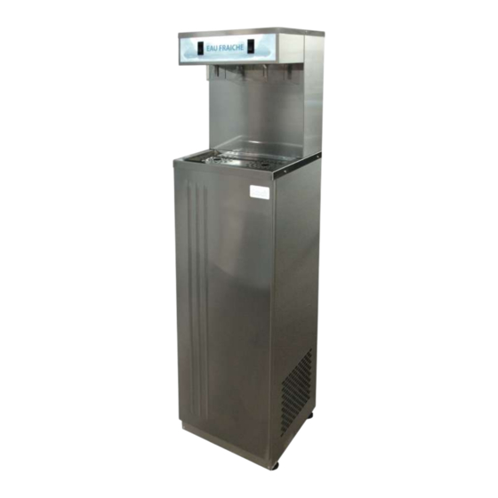
- Page 5 DIMENSIONS (en mm) FONTAINE : 1420x350x400 CARTON : 1450x410x430 POIDS : 45 kg COMPRESSEUR : 1/5 ch CHARGE : 180g GAZ : R134A ALIMENTATION (Volt/Hz) : 220 - 240 VAC / 50-60Hz INTENSITE : 1,40 A PUISSANCE : 300 W SYSTEME DE DISTRIBUTION D’EAU : 24 V PRESSION D’ENTREE MAXIMALE SUPPORTEE : 4 Bars (0.4Mpa) DEBIT : 300 L / H...
- Page 6 Une notice d’installation. Un tuyau d’arrivée d’eau 6x8mm noir. Un raccord instantané 12x17, 6/8mm mâle. Un tuyau de vidange 20x27 sortant de l’appareil pour l’évacuation. Un cordon électrique de 2 mètres. Un water block équipé avec son raccord (en option). Un filtre FILTROPURE triple action 5000 (en option).
- Page 7 Clavier pour le REC 80 M - eau froide : Eau froide Eau froide Clavier pour le REC 100 M - eau froide : Eau froide Eau froide...
- Page 8 Les opérations d’installation et de maintenance doivent être réalisées uniquement par un personnel qualifié. Contactez le service ou l’entreprise en charge de la maintenance pour toutes interventions. Avant de commencer l’installation de la fontaine Branchement en eau : prévoir à gauche ou à droite, près de la fontaine, un robinet d’arrêt avec une sortie en ¾...
- Page 9 Veillez à ce que la fontaine soit débranchée. A l’aide d’un tournevis cruciforme, dévisser la visse (1) située sur le coté, à droite, en haut de la façade (cf photo). Soulever la façade vers le haut (2), puis la dégager de son logement en tirant vers l’avant par le bas.
- Page 10 Branchement du filtre (en option). Fermer l’arrivée d’eau. Vider la pression du circuit d’eau. Retirer le raccord-coudé. Connecter le tube+rondelle (1) sur l’entrée du filtre (comme indiqué sur la photo). Respecter bien le sens de circulation d’eau du filtre matérialisation par une flèche.
- Page 11 Remise en route du water block Water block en Dans l’hypothèse ou le water block serait blo- position fermée. qué, réamorcer-le comme indiqué ci-dessous : Fermer l’arrivée d’eau Appuyer sur les boutons de distribution pour enlever la pression résiduelle du circuit d’eau. Dévisser le raccord plastique.
- Page 12 Veillez à ce que la fontaine soit débranchée. Ne jamais verser de chlorure de sodium (sel marin) ou ses dérivés (eau de javel) dans la cuve du bac de réfrigération contenant les serpentins inox. Nettoyage du condenseur Le condenseur est le radiateur situé devant le ventilateur. A l’aide d’un soufflet ou d’un aspirateur, dépoussiérer les ailettes du condenseur.
- Page 13 Contrôle des pannes TYPE DE PANNES CONTROLE A EFFECTUER PAS D’EAU LE ROBINET D’ARRIVEE D’EAU EST-IL OUVERT ? LE CORDON D’ALIMENTATION EST-IL BRANCHÉ ? LE WATER BLOCK EST-IL BLOQUE ? P.11 LE CORDON D’ALIMENTATION EST-IL BRANCHE ? PAS DE FROID LA CUVE EST-ELLE BIEN REMPLIE EN EAU ? LE COMPRESSEUR TOURNE -T-IL ? (Vibrations) LA COSSE DE LA POMPTE AGITATRICE EST-ELLE BRANCHEE ?
- Page 14 Schémas SCHEMA HYDRAULIQUE Electrovannes SCHEMA ELECTRIQUE PIECES ELEMENTAIRES vanne Contacteur Désignation 5210100 Compresseur 1/5 ch 5754002 Relais Compresseur 1/5 CH vanne Contacteur 5512001 Klixon 5582002 Moteur Ventilateur 5 W 5454002 Hélice Diamètre 200mm 6102000 Tube PE Noir 6x8 5840008 Thermostat Froid BDG 5727009 Raccord Inst.Equerre Egale 6x8 5328003...
- Page 16 PAGE 3 FRENCH VERSION RECOMMENDATIONS PAGE 17 - WATER COOLERS STORAGE PAGE 17 - TRANSPORTATION PAGE 17 - UTILISATION PAGE 17 PAGE 18 TECHNICAL SPECIFICATIONS WATER COOLER ACCESSORIES / PAGE 19 EQUIPMENT IDENTIFICATION CONTROL PANEL AND FUNCTIONS PAGE 20 INSTALLATION PAGE 21 to 23 SERVICE PAGE 24 to 27...
- Page 17 Please read through all of the following instructions carefully and keep them in a safe place for future reference. In case of servicing, for your security, always unplug the water cooler to avoid any risk of injuries or electric shocks. Never place your fingers or any metal object inside the water cooler.
- Page 18 MEASUREMENTSS (en mm) COOLER : 1420 x 350 x 400 : 1450x410x430 WEIGHT : 45 kg COMPRESSOR : 1/5 ch CHARGE : 180g GAS : R134A ELECTRICITY (Volt/Hz) : 220 - 240 VAC / 50-60Hz INTENSITE : 1,4 A WATT : 300 W WATER DISTRIBUTION SYSTEM : 24 V MAXIMUM INPUT PRESSURE : 4 Bars (0.4Mpa) FLOW RATE : 300 L / H...
- Page 19 One installation manual. One 6x8mm tube. One touch fitting 12x17, 6/8mm male. One drain tube 20x27 for draining. One 2 meters electrical plug. One water block equiped with its connector (n option). One triple action 5000 FILTROPURE filter (in option). One pressure reducer kit (in option).
- Page 20 Panel control for REC 80 M - cold water : Cold water Cold water Panel control for REC 100 M - cold water : Cold water Cold water...
- Page 21 The installation and maintenance operations have to be realised only by qualified persons. Please, contact your department or the company which is in charge of maintenances. Before setting up the water cooler Water supply : a stopcock with a female ¾ (20/27) output has to be located at the left or the right near the water cooler.
- Page 22 Make sure that water cooler is disconnected. Using a screwdriver, unscrew the screw (1) located on the side, right, at the top of the panel (see photo). Lift the cover up (2), then out of the slot by pulling forward, by down Remove the black cap from the tank.
- Page 23 Filter connection (in option). Turn off the water supply. Empty water pression of the circuit. Pull off the stem elbow. Connect the tube+rounded part (1) on the filter entrance (cf photo). Respect water flow circula- tion (see the arrow). CAUTION Do not flush out the filter trought the taps because it will damage the solenoid.
- Page 24 Water block unjamming Should the water block be jammed, you will have re-prime explained Water block OFF below : Turn off the water supply. Press the cold water button on the control panel to remove residual pressure in the water system.
- Page 25 Make sure that water cooler is disconnected. Never pour sodium chloride (salt) or its derivatives (bleach) in the tank containing stainless steel coils. Condenser cleaning The condenser is radiator, located front of the ventilator. Using a Bellows or a vacuum cleaner, Dust the condenser fins It is necessary to proceed to the cleaning of the condenser, at least 4 times a year.
- Page 26 Fault finding FAULT CHECKING NO WATER IS THE WATER SUPPLY TAP TURNED ON? IS THE POWER CABLE PLUGGED IN? IS THE WATERBLOCK JAMMED? P.23 NO COLD WATER IS THE POWER CABLE PLUGGED IN? IS THE TANK FILLED? DOES THE COMPRESSOR WORK? (Vibrations) IS THE AGITATOR PUMP SWITH ON? TOO COLD IS THE THERMOSTAT SET?
- Page 27 Spare parts drawing HYDRAULIC SCHEME Solenoid valves ELECTRIC SCHEME MAINS SPARE PARTS Désignation vanne Contacteur 5210100 Compressor 1/5 ch 5754002 Relay Compressor 1/5 ch 5512001 Klixon vanne 5582002 Fan engine 5w Contacteur 5454002 Fan diameter 200mm 6102000 6x8 black PE tube 5840008 Cold thermostat 5727009...
- Page 28 Pour plus d’informations contacter notre Service Après Vente For more information, please contact our After Sale Service : scodif@scodif.fr SCODIF 19, rue Jean Poulmarch BP 30059 95101 ARGENTEUIL CEDEX FRANCE Tel: 33 (0)1 39 81 43 43 Fax: 33(0)1 39 81 31 91 www.scodif.fr...