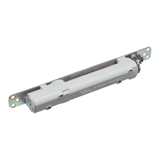
dorma ITS 96 EN 2-4/EN 3-6+ G 96 EMF Instructions De Montage
Masquer les pouces
Voir aussi pour ITS 96 EN 2-4/EN 3-6+ G 96 EMF:
- Instructions de montage (9 pages)
Publicité
DORMA
DORMA
MONTAGEANLEITUNG
Technische Daten EMF
Betriebsspannung:
Leistungsaufnahme:
Einschaltdauer:
Auslösemoment:
max. Türöffnungswinkel: 120°
Die Ansteuerung erfolgt über externe Rauchmeldezentrale
(z.B. DORMA RMZ 2 oder RZ 01 + RM).
Montagevorbereitung
● Türblatt und Rahmen gemäß Maßbild vorbereiten.
● Für elektromechanische Feststellung Stromzuführung
von Rauchmeldezentrale legen.
1
Endkappe aufclipsen, Gleitschiene in die
Ausnehmung einsetzen und anschrauben.
2
Kabel anschließen
3
Schließer in das Türblatt einsetzen und befestigen.
4
Ventil 120°-0° schließen. Schließerhebel aufsetzen.
Auf die richtige Lage des Vierkants im Hebel achten.
Nur dann ist eine einwandfreie Funktion des Tür-
schließers gewährleistet.
Schließerhebel um ca. 30° verdrehen.
5
Hebel abnehmen und um 90° versetzt wieder aufsetzen.
6
Schließerhebel mit Schließer und Gleitstück verbinden.
7
Schließgeschwindigkeit einstellen.
8
Schließkraft einstellen.
9
Endschlag einstellen.
10
Feststellpunkt einstellen
Spannung anlegen (24 V DC).
Türflügel öffnen und einrasten. Schrauben lösen.
Tür auf gewünschten Feststellwinkel öffnen und festhalten.
Schrauben wieder festziehen.
Die Tür kann maximal bis zum gewählten Feststellpunkt
geöffnet werden, an dieser Position Türstopper setzen.
11
Ausrückkraft einstellen
Je nach Türbreite und gewählter Schließergröße Aus-
rückkraft einstellen.
Nach EN 1155 soll das Ausrückmoment bei 90°
Türöffnungswinkel zwischen 40 - 120 Nm liegen.
Eine zu hoch eingestellte Kraft kann zu Beschädigun-
gen an den Türbändern und Befestigungselementen
des Türschließsystems führen .
Funktionsprüfung
Türflügel öffnen und feststellen.
Stromzufuhr unterbrechen - die Feststellung muß
auslösen.
ABNAHMEPRÜFUNG UND WARTUNG
☞
Merkblatt über die Verwendung von Feststellanlagen
WEITERE HINWEISE
☞
Richtlinien für Feststellanlagen des Instituts
für Bautechnik, Berlin.
DORMA GmbH + Co.KG
Door Control Division
ITS 96 EN 2-4/EN 3-6
+ G 96 EMF
24 V DC
1,4 W
100 % ED
ca. 25 - 65 Nm bei 90° Öffnungs-
winkel (abhängig von der am
Schließer eingestellten Schließkraft).
DORMA Platz 1
D-58256 Ennepetal • Tel. +49 (0) 23 33 / 793-0 • www.dorma.com
Postfach 40 09 D-58247 Ennepetal • Fax +49 (0) 23 33 / 79 34 95
FIXING INSTRUCTIONS
Technical Data EMF
Operating voltage:
24 V DC
Power input:
1,4 W
Rated for continuous duty: 100 %
Release torque:
approx. 25-65 Nm at an opening
angle of 90°(dependent upon the
strength setting of the door closer).
Door opening angle:
max. 120°
The unit is controlled by an external smoke detector unit
(e.g.DORMA RMZ 2 or RZ 01 + RM).
Praparations for fixing
● Prepare door leaf and frame as per dimensional drawing.
● For the electro-mechanical hold open, install power
supply cable from smoke detector.
1
Clip on the end cap, insert the slide channel in the
recess, and fix.
2
Conductor connections
3
Insert the closer in the door leaf and fix.
4
Close the 120° - 0° adjustment valve. Fit the closer arm.
Ensure that the square recess in the arm is positioned
correctly as this is critical for the door closer function.
Turn closer arm approx. 30° in the direction indicated.
5
Remove arm, turn 90° and re-fit.
6
Fix arm to closer and slide shoe.
7
Adjust closing speed.
8
Adjust closing force.
9
Adjust latch action.
10
Setting the hold-open point
Switch on power supply (24 V DC). Open door leaf and
engage hold open. Loosen screws. Open door leaf
until required hold-open angle is reached and hold-
open in this position. Tighten the screws.
The door cannot be opened beyond the hold
open point; fix a door stop at this position.
11
Setting the pull off force
Adjust the pull-off force to suit the door width and size of
door closer. EN 1155 states that the release torque at 90°
door opening angle should be between 40 and 120 Nm.
If the pull off force is set too high, damage might occur
to the hinges and the fixings of the door closer system.
Functional test
Open the door and engage hold open.
Interrupt the power supply and ensure that the hold
open mechanism releases the door.
FINAL INSPECTION AND MAINTENANCE
☞
See instruction sheet relating to the use and
application of hold open devices and systems.
FURTHER INFORMATION
☞
See guidelines for hold-open systems published by
the Institute for Building Technology, Berlin
equivalent national guidelines.
1 1 1 1 1
These documents are only printed in German as they refer exclusively to the
) ) ) ) )
German market.
1)
or
1)
Publicité
Table des Matières

Sommaire des Matières pour dorma ITS 96 EN 2-4/EN 3-6+ G 96 EMF
- Page 1 ) ) ) ) ) German market. DORMA Platz 1 D-58256 Ennepetal • Tel. +49 (0) 23 33 / 793-0 • www.dorma.com DORMA GmbH + Co.KG Postfach 40 09 D-58247 Ennepetal • Fax +49 (0) 23 33 / 79 34 95...
-
Page 2: Istruzioni Di Montaggio
La commande est effectué par la centrale externe de Il comando avviene tramite centralina esterna di rivelatori détection de fumée ( p. ex. DORMA RMZ 2 ou RZ 01+RM) di fumo (p.es. DORMA RMZ 2 o RZ 01 + RM). -
Page 3: Besiktning Och Underhåll
De lokale Brandpreventieve Dienst. DORMA Platz 1 D-58256 Ennepetal • Tel. +49 (0) 23 33 / 793-0 • www.dorma.com DORMA GmbH + Co.KG Postfach 40 09 D-58247 Ennepetal • Fax +49 (0) 23 33 / 79 34 95... -
Page 4: Control Y Mantenimiento
Instituto de la construcción en Berlín. DORMA Platz 1 D-58256 Ennepetal • Tel. +49 (0) 23 33 / 793-0 • www.dorma.com DORMA GmbH + Co.KG Postfach 40 09 D-58247 Ennepetal • Fax +49 (0) 23 33 / 79 34 95... -
Page 5: Instruções De Montagem
Ângulo máximo de abertura da porta: 120° A activação está a cargo de uma central de detecção de fumo externa (p. ex. DORMA RMZ 2 ou RZ 01 + RM). Preparativos para a montagem ● Preparar a folha da porta e o aro de acordo com o desenho dimensional.


