Table des Matières
Publicité
Les langues disponibles
Les langues disponibles
Liens rapides
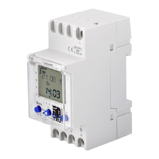
Operating instructions
Time switch for DIN rail
Item no. 2144015
Item no. 2144016
Intended Use
This product is designed to be used as a time switch to control electrical systems. It features up to two
individually programmable switching channels. The time switch models with item numbers 2144015 and
2144023 only feature one switching channel. The time switch has 58 programmable memory spaces in 29
blocks (on/off). You can configure a PIN to secure the time switch against unauthorised use. The time switch
can be configured to switch between summer and winter time. The time switch models with order numbers
2144023 and 2144025 feature a random/holiday mode, which can be configured to randomise switching
operations (e.g. when you are on holiday). This function is not available for item numbers 2144015 and
2144016.
The time switch is designed for standalone installation in a control cabinet by means of a symmetrical 35 mm
profile in accordance with EN 60715 standards (DIN rail).
This product is intended for indoor use only. Do not use it outdoors. Contact with moisture (e.g. in a bath-
room) must be avoided under all circumstances.
For safety and approval purposes, do not rebuild and/or modify this product. Using the product for purposes
other than those described above may damage the product. In addition, improper use can cause hazards
such as a short circuit, fire or electric shock. Read the operating instructions carefully and store them in a
safe place. Only make this product available to third parties together with its operating instructions.
This product complies with statutory, national and European regulations. All company and product names
contained herein are trademarks of their respective owners. All rights reserved.
Package contents
•
Time switch
•
Operating instructions
Up-to-date operating instructions
To download the latest operating instructions, visit www.conrad.com/downloads or scan
the QR code on this page. Follow the instructions on the website.
Explanation of symbols
The symbol with the lightning in a triangle indicates that there is a risk to your health, e.g. due to
an electric shock.
The symbol with an exclamation mark in a triangle is used to highlight important information in
these operating instructions. Always read this information carefully.
The arrow symbol indicates special information and tips on how to use the product.
Safety information
Read the operating instructions and safety information carefully. If you do not follow the
safety information and information on proper handling in these operating instructions,
we will assume no liability for any resulting personal injury or damage to property. Such
cases will invalidate the warranty/guarantee.
a) General information
• Protect the product from extreme temperatures, direct sunlight, strong jolts, high humidity,
moisture, flammable gases, vapours and solvents.
• Do not place the product under any mechanical stress.
• This product is not a toy. Keep it out of the reach of children and pets.
b) Installation
• Installation work must only be done by qualified personnel who are familiar with the potential
hazards and the relevant regulations.
• Before connecting the device, turn off the power circuit to which the device is to be connected.
Remove the corresponding main fuse or trip the automatic fuse.
• Ensure that all corresponding cables are dead. Ensure that the cables are isolated and that
the contact points are covered. Never use bare wires for the connection.
• The device is protected internally against interference by means of a protective circuit. Despite
these protective measures, very strong magnetic fields may impair its function.
• Interference can be avoided by observing the following installation rules:
- Do not install the device near inductive loads (e.g. motors, transformers or contactors).
- The power should be supplied via a separate mains circuit (with a mains filter if required).
- Inductive loads must be equipped with protective devices to reduce overvoltages (varistors,
RC filters).
• Check whether interference signals are emitted when the time switch is used together with
other devices in a system.
c) Connected devices
• Always observe the safety instructions and operating instructions of any other devices which
are connected to the product.
Item no. 2144023
Item no. 2144025
Product overview
12
15
18
21
24
5
Auto
9
6
3
4
0
3
1
2
3
4
5
6
7
-
MENU
Res
1
2
2
1
Display symbols
Auto
Automatic switching intervals
Date and time settings
C1 ON Status of switching channel is ON
Switch connection (only shown for models
C1
with 2 switch connections)
Winter time enabled
Hand symbol (on/off)
Voltage display (2 points flashing = supply
voltage is connected
3 points flashing = running on reserve)
Day of the week ( ) 1-7 > Mon-Sun
1-7
The C1 and C2 symbols are only used for item numbers 2144016 & 214025 with 2 relay connec-
tions. Other products have no additional channel symbols.
Installation and connection
4
5
6
L
μ
L
1 2
1 5
1 8
2 1
24
1 2
15
18
21
24
A uto
Auto
9
9
6
6
3
3
0
0
1
2
3
4
5
6
7
1
2
3
4
5
6
7
ok
MENU
ok
MENU
-
+
-
+
Res
Res
L
L
M
M
~
~
3
N
1
2
3
N
1
μ
2
μ
N
L1
L2
The time switches with item numbers 2144016 & 214025 feature two relay connections. The
right-hand connection diagram applies only to these models.
Operation and programming
a) Switching on/off and reset
•
To switch on the time switch, press and hold the Res button (1) for 1 second with a sharp object (e.g.
pen). All display elements will appear briefly, after which the time switch is ready to configure. To restore
the default settings during use, press the Res button again.
If you have configured a PIN or switch programs, these will not be deleted when the settings are
restored.
•
When the supply voltage is not connected, the LCD display switches off after 10 minutes to reduce bat-
tery consumption (sleep mode). To wake the display, briefly press the MENU (2) button.
•
When the time switch is powered by battery, three points will flash on the display. When it is connected
to the supply voltage, only two points will flash.
b) Settings overview (graphical)
1 Res button
6
2 MENU button
7
3
- button
4 Day of the week (1-7 --> Mon-Sun)
5 Configured switch times
8
(24 h digits and bars)
6 LCD display
7 Date
9
8 Time
ok
9 ok button
10
+ button
10
Prog
Programming mode
Manual settings
Man
C2 OFF Status of switching channel is OFF
Switch connection (only shown for
C2
models with 2 switch connections)
Summer time enabled
Programmed switch processes (for the
current day)
Bar display for the set switch times
Current day of the week (together with
the number)
1. Mount the time switch on a DIN-compliant rail. Care-
fully pull the locking lever downwards slightly. Click the
lock onto the rail and let go again.
2. Connect the time switch according to the connection
diagram. Clamp the connecting wires in place. Use a
Phillips screwdriver to tighten the screws.
N
L1
L2
Publicité
Table des Matières

Manuels Connexes pour TRU Components 2144015

Sommaire des Matières pour TRU Components 2144015
- Page 1 2144023 and 2144025 feature a random/holiday mode, which can be configured to randomise switching Switch connection (only shown for models Switch connection (only shown for operations (e.g. when you are on holiday). This function is not available for item numbers 2144015 and with 2 switch connections) models with 2 switch connections) 2144016.
-
Page 2: Basic Settings
c) Basic settings 11. In program mode, you can also select the Change, Delete and MENU End options (select with the - (3) or + (10) buttons and confirm 1. Press the Res (1) button to reset the time switch. All display ele- PROG with the ok (9) button). -
Page 3: Care And Cleaning
g) Setting and switching the cycle and pulse program 4. If the hand symbol flashes and is displayed together with "On" or "Off", this indicates that the relay Only for item nos. 2144023 & 2144025 connection is in the opposite switch position for the duration of the current switch interval: Cycle program - On, if it was switched off during the switch interval If two cycles overlap, the cycle with the earliest start time will be selected. -
Page 4: Technical Data
Technical data a) Item no. 2144015 Battery ..........3 V/DC, 1000 mAh (CR2477) Switching voltage ........Max. 250 V/AC Switching current ........Max. 16 A Protection rating ........IP20 Power reserve ........4 years Switching times ........Daily (24 hrs) and weekly programmes (7 days) Relay ............ -
Page 5: Temporisateur Pour Rails Din
Le produit sert de temporisateur pour la commande d'installations électriques ayant jusqu'à deux canaux de (24 h-chiffres et barres) commutation programmables individuellement. Pour les temporisateurs avec les N° de commande 2144015 6 Écran LCD et 2144023,un seul canal de commutation est disponible. Le temporisateur dispose de 58 emplacements 7 Date de mémoire programmables dans 29 blocs (on/off). -
Page 6: Aperçu Des Paramètres (Graphique)
b) Aperçu des paramètres (graphique) 11. En mode programmation, les options de modification, de suppres- MENU sion et de fin sont également disponibles (sélectionnez avec les PROG touches - (3) ou + (10) et validez avec la touche OK (9). Vous pouvez ensuite modifier directement les commandes de commuta- tion à... -
Page 7: Entretien Et Nettoyage
g) Configuration et commutation du programme de cycles et d'impulsions 4. Si le symbole de la main clignote et s’affiche avec « On » et « Off », le terminal relais est en position Uniquement avec les N° de commande 2144023 et 2144025 de commutation inverse pour la durée de l’intervalle de commutation actuel : Programme de cycles - Allumé... -
Page 8: Données Techniques
Données techniques a) N° de commande 2144015 Pile ............3 V/DC, 1000 mAh (CR2477) tension de commutation ....... max. 250 V/CA courant de commutation ....... 16 A max. Indice de protection ......IP20 Réserve de marche ......4 ans Horaires de mise en marche ....Programme jour (24 h) et semaine (7 jours) Relais ............ - Page 9 10 Knop + Doelmatig gebruik Displaypictogrammen Het product dient als timer voor het aansturen van elektrische systemen met maximaal twee individueel pro- grammeerbare schakelkanalen. Voor de timers met de bestelnummers 2144015 en 2144023 is slechts één Auto automatische schakelintervallen Prog Programmeermodus schakelkanaal beschikbaar.
-
Page 10: Basisinstellingen
c) Basisinstellingen 11. In de programmamodus kunt u de wijzigingsoptie selecteren, de op- MENU tie wissen en de optie beëindigen (selecteer met de knoppen - (3) 1. Druk op de knop Res (1) om de timer terug te zetten. Alle weer- PROG of + (10) en bevestig met ok (9)). -
Page 11: Onderhoud En Reiniging
g) Cyclus- en pulsprogramma instellen 4. Als het handsymbool knippert en samen met "Aan" en "Uit" wordt weergegeven, bevindt de Alleen voor de bestelnr. 2144023 & 2144025 relaisaansluiting zich gedurende het actuele schakelinterval in de omgekeerde schakelpositie: Cyclusprogramma - ingeschakeld indien uitgeschakeld tijdens het schakelinterval Als er twee overlappende cycli zijn ingesteld, wordt altijd de cyclus met de eerste starttijd uit- - uitgeschakeld indien ingeschakeld tijdens het schakelinterval. -
Page 12: Technische Gegevens
Technische gegevens a) Bestelnr. 2144015 Batterij ..........3 V/DC, 1000 mAh (CR2477) Schakelspanning ........max. 250 V/AC Schakelstroom ........max. 16 A Beschermingsgraad ......IP20 Geheugen-ondersteuningssysteem ..4 jaar Schakeltijden ........Dag- (24 h) en weekprogramma’s (7 dagen) Relais ............ 1 schakelende aansluiting Kortste schakeltijd ........