Table des Matières
Publicité
Les langues disponibles
Les langues disponibles
Liens rapides
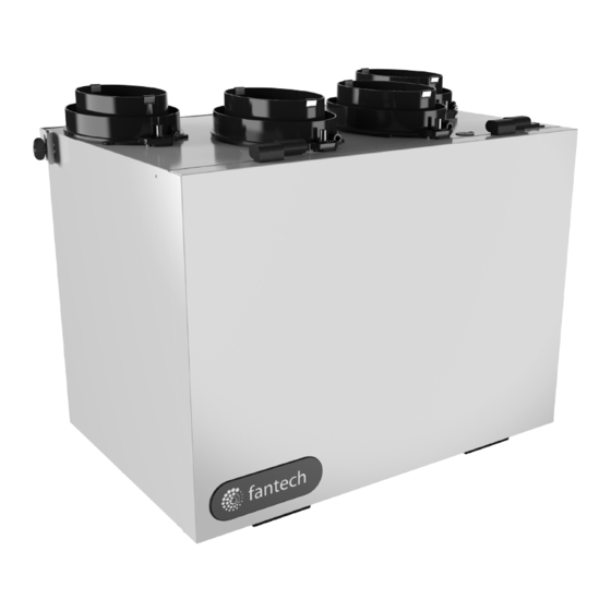
FLEX 100H • VHR70R • VHR100R •
VHR150R
Heat Recovery Ventilators
Your ventilation system should be installed in conformance with the appropriate provincial requirements or, in the absence of
such requirements, with the current edition of the National Building Code, and / or ASHRAE's "Good Engineering Practices".
United States
10048 Industrial Blvd., Lenexa, KS, 66215
Tel.: 800.747.1762 • Fax: 800.487.9915
Canada
50 Kanalflakt Way, Bouctouche, NB, E4S 3M5
Tel.: 800.565.3548 • Fax: 877.747.8116
Fantech reserves the right to modify, at any time and without notice, any or all of its products' features, designs,
components and specifications to maintain their technological leadership position.
Please visit our website www.fantech.net for more detailed technical information.
Installation Manual
Item #: 405335
Rev Date: 121514
fantech
Publicité
Chapitres
Table des Matières
Dépannage

Manuels Connexes pour Fantech FLEX 100H


Sommaire des Matières pour Fantech FLEX 100H
- Page 1 Tel.: 800.565.3548 • Fax: 877.747.8116 fantech Fantech reserves the right to modify, at any time and without notice, any or all of its products’ features, designs, components and specifications to maintain their technological leadership position. Please visit our website www.fantech.net for more detailed technical information.
- Page 2 Your ventilation system should be installed in accordance with the local building code that is in effect, in absence of such requirements, it is recommenced to check with local authorities having jurisdiction in your area prior to installing this product fantech...
-
Page 3: Table Des Matières
HRV MAINTENANCE CHART ..............17 fantech... -
Page 4: Determining Your Airflow Requirement
* ASHRAE 62.2-2010 Table 4.1, Ventilation and Acceptable Indoor Air Quality in Low-Rise Residential Buildings. Bathroom: If the HRV is going to provide the required local exhaust ventilation for each bathroom with each a continuous 20 CFM (10 L/s), this ventilation rate can be considered as part of the whole-building ventilation rate. fantech... -
Page 5: Installation Examples
The HRV’s airflow must be balanced after installation using the procedure found in the section “AIRFLOW BALANCING” HRV ducting for fully Dedicated System Stale air from inside Fresh air from outside Fresh air to living areas Outside Stale air to outside fantech... -
Page 6: Partially Dedicated System
Fresh air Fresh air from to living outside areas 1 m (3' 3") min. Outside recommended Return plenum Stale air to * Unit airflow should be balanced while HRV is on outside “Normal” speed and furnace blower is running. fantech... -
Page 7: Simplified Installation
Stale air from inside Fresh air from 1 m (3' 3") min. outside recom- mended Outside Cold air return Stale air to * Unit airflow should be balanced while HRV is on outside “Normal” speed and furnace blower is running. fantech... -
Page 8: Exterior Ducting Installation
Pull the insulation procedure for both the supply insulated flexible duct. Cut a over the duct and pull the vapor and exhaust hoods. hole for both the intake and barrier over the sleeve. Secure exhaust hoods. with appropriate tape or sealant. fantech... -
Page 9: Interior Ducting Installation
In this method, the exhaust air is not ducted back from bathrooms, kitchens, etc to the HRV with “dedicated lines”. As per building codes and installation requirements for combustion appliances: Air return ducts, or openings for air return, should not be placed in enclosed spaces containing combustion appliances that are subject to spillage. fantech... -
Page 10: Hrv Installation
(3/4") bolt (provided) in the in the links so a loop is hooks, making sure the top 4 corners of the unit created in the chain. The unit is level. and tighten. spring will then support the unit's weight and absorb vibrations. fantech... -
Page 11: Airflow Adjustment & Balancing
The integrated dampers are preset at the fully opened position. In order to reduce the amount of airflow, turn the adjustable lever using a flat screw driver by turning it counter clock wise. Turning the lever clockwise may damage the plastic screw head. Follow the balancing steps to properly adjust the airflow. fantech... -
Page 12: Balancing Steps
STEP #3: Secure the adjustable arm by tightening the set screw as shown in Illustration #3. Illustration #1 Set screw (on top) Adjustment lever (in front) Illustration #2 Illustration #3 fantech... -
Page 13: Low Voltage Control Systems
• Up to 5 can be used in one system • Use in bathroom, kitchen, laundry room MDEH1 • Rotary dial Dehumidistat • Multiple units can be used • We recommend setting the relative humidity above 80% during the summer fantech... -
Page 14: Wiring Diagram
WIRING DIAGRAM fantech... - Page 15 24-VOLT TERMINAL BLOCK COOLING SYSTEM WIRE As per building codes and installation requirements for combustion appliances: Air return ducts, or openings for air return, should not be placed in enclosed spaces containing combustion appliances that are subject to spillage. fantech...
-
Page 16: Troubleshooting
Everything is in good operations LED is not flashing No Power is being transmitted to the Control Board Make sure unit is plugged. Transformer may need replacing. Note: It is best to get the unit checked by a certified HVAC Contractor/Technician. fantech... -
Page 17: Hrv Maintenance Chart
Lines the beginning of the warranty period. Vacuum the Inside of the Annually • The fans found in all Fantech HRVs Unit require no lubrication, and are factory balanced to prevent vibration Clean and Un-block Annually and promote silent operation. - Page 18 NOTES fantech...
-
Page 19: Ventilateur Récupérateur De Chaleur
Tél.: 800.565.3548 • Fax: 877.747.8116 fantech Fantech se réserve le droit de modifier partiellement ou entièrement, en tout moment et sans préavis, les caractéristiques, la conception, les composants et les spécifications de ses produits, afin de conserver sa position de leader de technologie. -
Page 20: Veuillez Lire Le Manuel Avant D'installer L'appareil
Votre système de ventilation doit être installé en conformité avec le code du bâtiment local qui est en vigueur, en l’absence de telles exigences, il est recommandé de vérifier auprès des autorités locales ayant juridiction dans votre région avant d’installer ce produit. fantech... - Page 21 TABLEAU D'ENTRETIEN DU VRC..............35 fantech...
-
Page 22: Déterminer Vos Besoins De Ventilation
Salle de bain: Si le VRC fournit la ventilation d’échappement locale requise pour chaque salle de bain avec chacun un 20 PCM continue (10L/s), ce taux de ventilation peut être considéré comme faisant partie du débit de ventilation de tout le bâtiment. fantech... -
Page 23: Exemples D'installation
Le débit d’air du VRC doit être confirmé sur place au moyen de la procédure d’équilibrage du présent manuel d’installation. Conduit VRC/Fournaise de Système entièrement spécialisé Air vicié provenant de l'intérieur Air frais provenant de l'extérieur Air frais distribué à l'intérieur Extérieur Air vicié évacué à l'extérieur fantech... -
Page 24: Système Partiellement Spécialisé
à de l'extérieur l'intérieur 1 m (3pi) min. Extérieur recommendeé Retour d'air frais Fournaise à Air vicié air pulsé *L’appareil est équilibré à vitesse normale et pendant évacué à que le ventilateur de la fournaise est en marche. l'extérieur fantech... -
Page 25: Installation Simplifiée
Air frais provenant 1 m (3'pi) min. de l'extérieur recomman- dé Extérieur Fournaise à air pulsé Retour d'air frais Air vicié évacué *L’appareil est équilibré à vitesse normale et pendant que le à l'extérieur ventilateur de la fournaise est en marche. fantech... -
Page 26: Installation Des Conduits Extérieurs
Percez un Fixez à l’aide de ruban adhésif trou pour la hotte d’aspiration en toile. et un trou pour la hotte d'échappement fantech... -
Page 27: Installation Des Conduits Intérieurs
Selon les codes du bâtiment et les codes d'installation des appareils de combustion, il est interdit de poser des grilles de reprise d'air ou de percer une ouverture pour une prise d'air dans une piêce close où se trouvent des appareils à combustion sujet à des déversements. fantech... -
Page 28: Montage- Support Mural
Le ressort suspension et assurez vous VRC et serrez. supportera le poids du VRC et que l’appareil est de niveau. absorbera les vibrations. fantech... -
Page 29: Équilibrage Du Débit D'air
Joint d'étanchéité boucle (siphon en P). pas requis avec la série FLEX 100H et VHR 100R Fixer la conduite de condensat à la connexion de drainage à l'aide d'une attache ou d'une autre méthode appropriée. ÉQUILIBRAGE DU DÉBIT D’AIR SI LES FLUX D’AIR DE L’APPAREIL NE SONT PAS CORRECTEMENT ÉQUILIBRÉS…... -
Page 30: Étapes De Balancement
Illustration n° 1 Étape 3: Fixez le bras de réglage en serrant la vis de fixation comme indiqué dans l'illustration no3. Vis de fixation (au dessus) Bras de réglage (à l'avant) Illustration n° 2 Illustration n° 3 fantech... -
Page 31: Systèmes De Contrôle À Basse Tension
• Jusqu'à 5 peuvent être utilisés dans un système • Utilisation pour salle de bain, cuisine, buanderie • Déshumidistat cadran rotatif MDEH1 • Multiple appareil peuvent être utilisés • Nous vous recommandons de régler l’humidité relative au-dessus de 80% au cours de l’été fantech... -
Page 32: Schémas Électroniques
SCHÉMAS ÉLECTRONIQUES fantech... - Page 33 COOLING SYSTEM SYSTÈME DE DEUX FILS WIRE REFROIDISSEMENT Ne raccordez jamais un courant alternatif de 120V aux bornes de synchronisation de la fournaise. N'utilisez que le conduit basse tension de classe 2 de la commande du ventilateur de la fournaise. fantech...
-
Page 34: Dépannage
DEL ne clignote pas – La plaquette électronique n'est pas alimentée – S'assurer que la plaquette est branchée – Remplacer le transformateur si nécessaire. Note: Il est toujours recommandé de faire vérifier l'appareil par un Contracteur/Technicien certifié en CVC fantech... -
Page 35: Tableau D'entretien Du Vrc
à proximité du domicile de l'acheteur ou dans sa région. • Fantech se réserve le droit de fournir des pièces remises à neuf comme pièces de rechange. • Les frais de transport, de retrait et d'installation sont assumés par... - Page 36 Fantech reserves the right to make technical changes. Fantech se réserve le droit de faire des changements tech- For updated documentation please refer to www.fantech.net niques. Pour de la documentation à jour, s'il vous plaît se référer au www.fantech.net Fantech®...