Table des Matières

Publicité

Les langues disponibles

Les langues disponibles

Liens rapides

DE
Anleitung für die Montage, Betrieb und Wartung
ANAEROBIX Filter im Herkules
>> Seite 1-11
EN
Instructions for Assembly, Operation and Maintenance
ANAEROBIX Filter in Herkules Tank
>> Page 12-22
Notice d'installation et d'utilisation du
FR
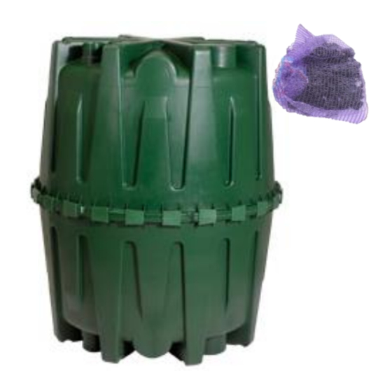
Filtre ANAEROBIX dans le réservoir Hercule
>> Page 23-33
ES
Instrucción para el montaje, funcionamiento y mantenimiento
Filtro ANAEROBIX Herkules
>> Página 34-44
ANAEROBIX

Publicité

Table des Matières
loading

Sommaire des Matières pour Graf ANAEROBIX

  • Page 1 Instructions for Assembly, Operation and Maintenance ANAEROBIX Filter in Herkules Tank >> Page 12-22 Notice d’installation et d’utilisation du Filtre ANAEROBIX dans le réservoir Hercule >> Page 23-33 Instrucción para el montaje, funcionamiento y mantenimiento Filtro ANAEROBIX Herkules >> Página 34-44...
  • Page 2: Table Des Matières

    Anleitung für die Montage, Betrieb und Wartung ANAEROBIX Filter im Herkules 106534 Nachrüstset ANAEROBIX im Herkules Inhaltsübersicht Die in dieser Anleitung beschrie- benen Punkte sind unbedingt zu LIEFERUMFANG beachten. Bei Nichtbeachtung er- EINBAUBEDINGUNGEN, EINBAU UND MONTAGE lischt jeglicher Garantieanspruch.
  • Page 3: Lieferumfang

    1. Lieferumfang 1. Lieferumfang Herkules-Stützrohr Filterrohr DN 160 Rohr-Formstücke Netzsack mit Trägermaterial Dichtungen, Endkappen Erforderliches Zubehör zur Montage: 202003 Kronenbohrer Ø 124 mm 332002 Kronenbohrer Ø 175 mm 2 / 44...
  • Page 4: Einbaubedingungen, Einbau Und Montage

    2. Einbaubedingungen, Einbau und Montage 2. Einbaubedingungen, Einbau und Montage Der Einbau des Behälters wird nach der dem Behälter beiliegenden Einbauanleitung vorgenommen. Weiterhin sind die dort beschriebenen Einbaubedingungen des jeweiligen Behälters zu beachten. 3 / 44...
  • Page 5: Abmessungen

    3. Abmessungen Abmessungen DN200 DN200 1325 4 / 44...
  • Page 6: Montage Des Rüstsatzes

    4. Montage des Rüstsatzes 4. Montage des Rüstsatzes Obere Halbschale Obere Halbschale Zu- und Ablauf gegenüberliegend mit Kronenboh- Beide Stutzen DN 200 mit Kronenbohrer DN 160 rer DN 110 bohren (Ø 124 mm). (Ø 175 mm) aufbohren oder mit Stichsäge öffnen. Obere Halbschale Bohrung entgraten.
  • Page 7 4. Montage des Rüstsatzes Obere Halbschale Obere Halbschale Dichtung des Herkules Tanks einsetzen. Einbau- Rohrstück DN 110 mit Spitzende von außen durch anleitung des Herkules Tanks beachten! die Bohrung des Auslaufes stecken. Obere Halbschale Obere Halbschale Herkules Stützrohr in die Mitte der oberen Halb- Filterrohr mit dem Auslaufrohr verbinden und in schale stellen.
  • Page 8 4. Montage des Rüstsatzes Ø 8 mm Sack mit Trägermaterial Netzsack mit Trägermaterial unterhalb des Aus- Auf der Endkappe DN 160 mittig eine Loch Ø 8 laufrohres schieben mm bohren. Die Schnur mit der der Netzsack fest- gebunden ist durch das Loch fädeln und mit einem Knoten sichern.
  • Page 9: Installation Schlammentleerungsmodul (Optional)

    5. Installation Schlammentleerungsmodul (optional) 5. Installation Schlammentleerungsmodul (optional) Der Anaerobix im Herkules Tank kann mit einem zusätzlichem Schlammentleerungsmodul ausgestattet werden. Durch öffen eines Ventils kann der Bodenschlamm aus dem Herkules in einen seperaten Schacht geleitet werden. Wir empfehlen die Ausführung des Schlammentleerungsmoduls in DN 100. Ventile in DN 50 und DN63 können ebenfalls bei der Otto Graf GmbH bezogen werden.
  • Page 10: Installation Des Optionalen Schlammentleerungsmodul

    5. Installation Schlammentleerungsmodul (optional) Installation des optionalen Schlammentleerungsmodul Untere Halbschale Bohrung DN100 in der unteren Halbschale erstel- Verrohrung zum Entschlammungsmodul wie oben len und mit Lippendichtung DN100 versehen. dargestellt erstellen. 9 / 44...
  • Page 11: Betrieb Und Wartung

    Die Schlammabfuhr hat spätestens dann zu erfolgen, wenn der Schlammspiegel auf 70 % angestiegen ist. Reinigung des ANAEROBIX-FILTER Der ANAEROBIX-Filter ist regelmäßig auf Verstopfungen oder Überstau zu überprüfen. Wenn erforderlich, den Sack mit dem Trägermaterial aus dem Filterrohr entnehmen und reinigen. Wir empfehlen eine Reinigung des Trägermaterials mit einem Wasserschlauch.
  • Page 12 Die Anlage ist zu belüften. Falls erforderlich, sind zusätzliche Lüftungsleitungen oder Lüftungsöffnungen anzuordnen. Dabei sind Lüftungsleitungen so anzuordnen, dass eine natürliche Lüftung möglich ist (Kaminwirkung). Entlüftung bei freiem Ablauf Entlüftung bei Versickerung oder nicht freiem Ablauf 11 / 44 www.graf.info 2017-09...
  • Page 13 Instructions for Assembly, Operation and Maintenance ANAEROBIX Filter in Herkules Tank 106534 ANAEROBIX retrofit kit in Herkules tank Contents The points described in these in- structions must be observed in all SCOPE OF SUPPLY cases. Failure to do so shall invali- INSTALLATION CONDITIONS, INSTALLATION AND date the warranty.
  • Page 14: Scope Of Supply

    1. Scope of supply 1. Scope of supply Herkules support pipe DN 160 filter pipe Pipe fittings Mesh bag with carrier material Seals, end caps Required accessories for assembly: 202003 core drill, diameter 124 mm 332002 core drill, diameter 175 mm 13 / 44...
  • Page 15: Installation Conditions, Installation And Assembly

    2. Installation conditions, installation and assembly 2. Installation conditions, installation and assembly The tank is installed in accordance with the installation instructions supplied with it. The installation condi- tions for the relevant tank as described in the instructions should also be observed. 14 / 44...
  • Page 16: Dimensions

    3. Dimensions Dimensions DN200 DN200 1325 15 / 44...
  • Page 17: Fitting The Installation Kit

    4. Fitting the installation kit 4. Fitting the installation kit Upper half-shell Upper half-shell Drill inlet and outlet on opposite sides with DN Drill open the two DN 200 fittings with DN 160 core 110 core drill (diameter 124 mm). drill (diameter 175 mm) or cut open with a jigsaw.
  • Page 18 4. Fitting the installation kit Upper half-shell Upper half-shell Fit seal on Herkules tank. Follow installation in- Insert DN 110 pipe section through outlet hole structions for Herkules tank! from the outside, narrower end first. Upper half-shell Upper half-shell Position Herkules support pipe in centre of upper Connect filter pipe to outlet pipe and fit in the DN half-shell.
  • Page 19 4. Fitting the installation kit Diameter Bag with carrier material Slide mesh bag with carrier material down to be- In the centre of the DN 160 end cap, drill a hole 8 low the outlet pipe. mm in diameter. Thread the cord tying the bag through the hole and secure with a knot.
  • Page 20: Installation Of The Sludge Removal Module (Optional)

    5. Installation of the sludge removal module (optional) The Anaerobix in the Herkules tank can be equipped with an additional sludge removal module. Through the opening of a valve, sludge at the base of the tank can be routed from the Herkules into a separate shaft.
  • Page 21: Installation Of Optional Sludge Removal Module

    5. Installation of the sludge removal module (optional) Installation of optional sludge removal module Lower half-shell Drill a DN 100 hole in the lower half-shell and seal Fit pipes to connect the sludge removal module as with DN 100 edge seal. shown above.
  • Page 22: Operation And Maintenance

    Sludge removal must take place no later than when the sludge level has risen to 70%. Cleaning the ANAEROBIX FILTER The ANAEROBIX filter should be checked regularly for blockages or overflow. If necessary the bag con- taining the carrier material should be removed from the filter pipe and cleaned. We recommend cleaning the carrier material with a water hose.
  • Page 23 The system should be ventilated. Additional ventilation ducts or openings should be arranged if required. The ventilation ducts should be arranged so that natural ventilation is possible (chimney effect). Ventilation with unobstructed outflow Ventilation in the case of infiltration or with obstructed outflow 22 / 44 www.graf.info 2017-09...
  • Page 24 Notice d’installation et d’utilisation du Filtre ANAEROBIX dans le réservoir Hercule 106534 Kit filtre ANAEROBIX pour Hercule Table des matières Afin de garantir le bon fonctionne- ment et la longévité de votre instal- MATERIEL FOURNI lation, les différents points décrits CONDITIONS D’INSTALLATION ET DE MONTAGE...
  • Page 25: Materiel Fourni

    1. Matériel fourni 1. Matériel fourni Tuyau de maintien pour Hercule Tuyau de filtration DN 160 Manchons et réducteur PVC Filet média filtrant Joints à lèvres, bouchon Accessoires nécessaires non fournis, à commander séparément: Ref : 202003 Scie cloche Ø 124 mm Ref : 332002 Scie cloche Ø...
  • Page 26: Conditions D'installation Et De Montage

    2. Conditions d’installation et de montage 2. Conditions d’installation et de montage La notice d’installation et de montage est jointe à la livraison du réservoir. Veuillez respecter les instructions. 25 / 44...
  • Page 27: Donnees Techniques

    3. Données techniques Données techniques DN200 DN200 1325 Regard universel GRAf ref 330430 pour vidange manuel Entrée DN110 Sortie DN110 26 / 44...
  • Page 28: Montage Du Kit Filtre Anaerobix

    4. Montage du kit Filtre Anaerobix 4. Montage du kit Filtre Anaerobix Demi-coque supérieure Demi-coque supérieure Percer l’entrée et sortie pour l’alimentation et Percer les ouvertures DN 200 avec une scie cloche l’évacuation en haut du réservoir avec une scie DN 160 (Ø...
  • Page 29 4. Montage du kit Filtre Anaerobix Demi-coque supérieure Demi-coque supérieure Placer le joint d’étanchéité du réservoir Hercule Insérer le manchon PVC DN110 de l'extérieur vers selon les instructions de la notice d’installation. l’intérieur dans le joint. Demi-coque supé- Demi-coque supé-...
  • Page 30 4. Montage du kit Filtre Anaerobix Ø 8 mm Sachet média filtrant Pousser le sachet média filtrant dans le tuyau en Percer un trou de Ø8mm au centre du bouchon et dessous de la conduite d’évacuation. faites glisser la cordelette du sachet média filtrant et faites un nœud pour sécuriser.
  • Page 31: Installation Du Systeme De Vidange Des Boues (En Option)

    5. Installation du système de vidange des boues (en option) Le kit filtre Anaerobix installé dans le réservoir Hercule peut être équipé d'un système de vidange des boues en option. Par l'ouverture d'une vanne, il est possible de transférer les boues du fond vers un autre point de stockage.
  • Page 32: Installation Du Système De Vidange Des Boues En Option

    5. Installation du système de vidange des boues (en option) Installation du système de vidange des boues en option Demi-coque inférieure Percer une ouverture en DN 110 dans la demi- Installer une conduite menant au système de vi- coque inférieure puis placer le joint à lèvres DN dange comme illustré...
  • Page 33: Utilisation Et Maintenance

    Les boues doivent être évacuées avant d’avoir atteint 70 % du volume utile du réservoir. Nettoyage du FILTRE ANAEROBIX Contrôlez régulièrement le filtre ANAEROBIX pour s’assurer qu’il ne soit ni colmaté ni submergé. Au be- soin retirez le filet du tuyau percé et nettoyez le média filtrant avec un jet d’eau.
  • Page 34 L’installation doit être ventilée et aérée. Si nécessaire, ajoutez des tuyaux de ventilation ou des ouver- tures supplémentaires. Posez les tuyaux de ventilation afin de permettre une ventilation naturelle de la cuve (effet de cheminée). Ventilation avec écoulement libre Ventilation avec système d’infiltration ou écoulement non libre 33 / 44 www.graf.info 2017-09...
  • Page 35 Instrucciones de montaje, funcionamiento y mantenimiento Filtro ANAEROBIX Herkules 106534 Set de reequipamiento ANAEROBIX en el depósito Herkules Índice de contenido Los puntos descritos en esta instrucción deben ser respetados VOLUMEN DE SUMINISTRO obligatoriamente. Si no se CONDICIONES PARA LA INSTALACIÓN, observan las instrucciones INSTALACIÓN Y MONTAJE...
  • Page 36: Volumen De Suministro

    1. Volumen de suministro 1. Volumen de suministro Herkules-tubo de soporte estructural Tubo de filtro DN 160 Accesorios para el tubo Bolsa de malla con material filtrante Juntas y tapones Accesorios requeridos para el montaje: 202003 Broca de corona Ø 124 mm 332002 Broca de corona Ø...
  • Page 37: Condiciones Para La Instalación, Instalación Y Montaje

    2. Condiciones para la instalación, instalación y montaje 2. Condiciones para la instalación, instalación y montaje La instalación del depósito se realiza siguiendo las instrucciones de instalación incluidas con el mismo. Aparte de esto, se deberán respetar las condiciones de instalación específicas de cada depósito descritas en dichas instrucciones.
  • Page 38: Dimensiones

    3. Dimensiones Dimensiones DN200 DN200 1325 37 / 44...
  • Page 39: Montaje Del Kit De Instalación

    4. Montaje del kit de instalación 4. Montaje del kit de instalación Mitad superior Mitad superior del depósito depósito Taladrar los agujeros de entrada y salida uno Taladrar en ambos conectores DN 200 un agujero enfrente del otro utilizando la broca de corona DN (Ø...
  • Page 40 4. Montaje del kit de instalación Mitad superior del Mitad superior del depósito depósito Insertar la junta del depósito Herkules. ¡Leer las Insertar el tubo DN 110 desde fuera hacia dentro. instrucciones instalación depósito Herkules! Mitad superior del Mitad superior del depósito depósito Unir el tubo de filtro al tubo de salida y colocarlo...
  • Page 41 4. Montaje del kit de instalación Ø 8 mm Saco con Material filtrante Insertar el saco de malla con el material filtrante Taladrar un agujero Ø 8 mm en el centro de la debajo del tubo de salida tapa DN 160. Pasar la cuerda con la que se ha atado el saco de malla por el agujero y asegurarla haciendo un nudo.
  • Page 42: Instalación Del Módulo Para El Vaciado De Lodos Manual (Opcional)

    5. Instalación del módulo para el vaciado de lodos manual (opcional) La fosa filtro Anaerobix Herkules puede equiparse con un módulo para vaciado manual de lodos adicional. Abriendo una válvula los lodos depositados en el fondo del depósito Herkules pueden evacuarse a una arqueta separada.
  • Page 43: Instalación Del Módulo De Vaciado De Lodos (Opcional)

    5. Instalación del módulo para el vaciado de lodos manual (opcional) Instalación del módulo de vaciado de lodos (opcional) Mitad inferior del depósito Taladrar un agujero DN100 en la mitad inferior del Tender la tubería hacia el módulo de evacuación depósito y proveerlo de la junta labial DN100.
  • Page 44: Funcionamiento Y Mantenimiento

    70%. Limpieza del FILTRO ANAEROBIX Revisar periódicamente el filtro ANAEROBIX para detectar si presenta obstrucciones o crecidas de nivel. Siempre que resulte necesario retirar el saco con el material filtrante del tubo de filtro y limpiarlo. Recomendamos limpiar el material filtrante con una manguera de agua.
  • Page 45 Hay que airear la fosa filtro. En caso necesario hay que disponer conductos o agujeros de aireación adicionales. Las tuberías de aireación se deben disponer de tal forma que se permita una aireación natural (efecto chimenea). Aireación con salida libre Aireación en caso de infiltración de agua tratada o salida restringida 44 / 44 www.graf.info 2017-09...
  • Page 46 Notizen / Notes / Notas...
  • Page 47 Notizen / Notes / Notas...
  • Page 48 Notizen / Notes / Notas...

Table des Matières