Table des Matières
Publicité
Les langues disponibles
Les langues disponibles
Liens rapides
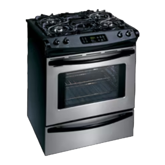
30" GAS SLIDE-IN RANGE INSTALLATION INSTRUCTIONS
INSTALLATION AND SERVICE MUST BE PERFORMED BY A QUALIFIED INSTALLER.
IMPORTANT: SAVE FOR LOCAL ELECTRICAL INSPECTOR'S USE.
READ AND SAVE THESE INSTRUCTIONS FOR FUTURE REFERENCE.
If the information in this manual is not followed exactly, a
fire or explosion may result causing property damage, personal injury or
death.
FOR YOUR SAFETY:
— Do not store or use gasoline or other flammable vapors and liquids in
the vicinity of this or any other appliance.
— WHAT TO DO IF YOU SMELL GAS:
•Do not try to light any appliance.
•Do not touch any electrical switch; do not use any phone in your building.
•Immediately call your gas supplier from a neighbor's phone. Follow the
gas supplier's instructions.
•If you cannot reach your gas supplier, call the fire department.
— Installation and service must be performed by a qualified installer,
service agency or the gas supplier.
These surfaces should be
flat & leveled (hatched
area).
Shave
Raised
Edge to
Clear
Space for a
31½" (81
cm) Wide
Cooktop.
Locate Cabinet Doors 1" (2.5 cm)
Min. from Cutout Opening.
A. HEIGHT
B. WIDTH
35 5/8" (90.5 cm) -
30" (76,2 cm)
36 5/8" (93cm)
NOTE: Wiring diagram for these appliances are enclosed in this booklet.
Printed in United States
(Models with Sealed Top Burners)
5" Min.
(12.7 cm Min.)
From Wall Both Sides
1 ½" Max.
(3.8 cm Max.)
C. COOKTOP
D. DEPTH TO
WIDTH
FRONT OF RANGE
31½" (80 cm)
28 5/16" (71,9 cm)
30" Min.
(76.2 cm Min.)
30" Min.
(76.2 cm) Min. (see
Note 3)
E
31 1/2"
(81 cm)
Exact
G
F
Grounded Junction Box or Wall Outlet Should Be Located 8"
to 17" (20.3 cm to 43.2 cm) From Right Cabinet and 2" to
4" (5.1 cm to 10.2 cm) From Floor.
E. CUTOUT WIDTH ***
(Countertop and Cabinet)
30±1/16"
(76,2±0,15 cm)
1
Refer to your serial plate for
applicable agency certification
Appliances Installed in the
state of Massachusetts:
This Appliance can only
be installed in the state of
Massachusetts by a Massachusetts
licensed plumber or gasfitter.
This appliance must be installed
with a three (3) foot/ 36 in. long
flexible gas connector.
A"T" handle type manual gas
valve must be installed in the gas
supply line to this appliance.
(33 cm)
18" Min.
(45.7 cm) Min.
Approx. 1 7/8"
(4.8 cm)
24" Min.
(61 cm Min.)
F. CUTOUT
G. HEIGHT
DEPTH
OF COUNTERTOP
21 3/4" (55,2 cm) Min.
36 5/8" (93 cm) Max.
22 1/8" (56,2 cm) Max
35 5/8" (90.5 cm) Min.
24" (61 cm) Min. with
backguard
P/N 318201673 (1301) Rev. D
English – pages 1-9
Español – páginas 10-18
Français - pages 19-28
Wiring Diagrams - pages 31-32
13"
Publicité
Table des Matières

Manuels Connexes pour Frigidaire FGS365EC


Sommaire des Matières pour Frigidaire FGS365EC
- Page 1 30" GAS SLIDE-IN RANGE INSTALLATION INSTRUCTIONS (Models with Sealed Top Burners) INSTALLATION AND SERVICE MUST BE PERFORMED BY A QUALIFIED INSTALLER. IMPORTANT: SAVE FOR LOCAL ELECTRICAL INSPECTOR'S USE. READ AND SAVE THESE INSTRUCTIONS FOR FUTURE REFERENCE. If the information in this manual is not followed exactly, a Refer to your serial plate for fire or explosion may result causing property damage, personal injury or applicable agency certification...
-
Page 2: Important
30" GAS SLIDE-IN RANGE INSTALLATION INSTRUCTIONS (Models with Sealed Top Burners) NOTE: 1. Do not pinch the power supply cord or the flexible gas conduit between the range and the wall. 2. Do not seal the range to the side cabinets. 3. -
Page 3: Important Safety Instructions
30" GAS SLIDE-IN RANGE INSTALLATION INSTRUCTIONS (Models with Sealed Top Burners) Important Notes to the Installer Never leave children alone or 1. Read all instructions contained in these installation unattended in the area where an appliance is in instructions before installing range. use. -
Page 4: Cabinet Construction
30" GAS SLIDE-IN RANGE INSTALLATION INSTRUCTIONS (Models with Sealed Top Burners) Cabinet Construction Provide an adequate Gas Supply When shipped from the factory, this unit is designed To eliminate the risk of cabinet burns and to operate on 4"(10,16 cm) water column (1.0 kPa) fire, do not have cabinet storage space above the range. -
Page 5: Lp/Propane Gas Conversion
30" GAS SLIDE-IN RANGE INSTALLATION INSTRUCTIONS (Models with Sealed Top Burners) Connect the range to the gas p l i supply Important: Remove all packing material and literature from range before connecting gas and electrical supply. To prevent leaks, put pipe joint sealant on all external pipe threads. -
Page 6: Electrical Requirements
30" GAS SLIDE-IN RANGE INSTALLATION INSTRUCTIONS (Models with Sealed Top Burners) Electrical Requirements Range Installation Important Note: Door removal is not a requirement for 120 volt, 60 Hertz, properly grounded dedicated circuit installation of the range, but is an added convenience. protected by a 15 amp circuit breaker or time delay fuse. -
Page 7: Leveling The Range
30" GAS SLIDE-IN RANGE INSTALLATION INSTRUCTIONS (Models with Sealed Top Burners) Installation With Backguard Burner Cap A backguard kit can be ordered through a Service Center. The cutout depth (21 3/4" (55.2 cm) Min., 22 1/8" (56.2 cm) Max.) needs to be increased to 24" (61 cm) when installing a backguard Installation With End Panel An end panel kit can be ordered through a Service... -
Page 8: Air Shutter-Broil Burner
30" GAS SLIDE-IN RANGE INSTALLATION INSTRUCTIONS (Models with Sealed Top Burners) 10.5 Operation of Oven Burners and Oven front of oven bottom from oven front frame, and pull the oven bottom out of the oven. Remove burner baffle so that Adjustments burner flame can be observed. - Page 9 30" GAS SLIDE-IN RANGE INSTALLATION INSTRUCTIONS (Models with Sealed Top Burners) Brackets attach to the floor at the back of the range to Anti-Tip Brackets Installation hold both rear leg levelers. When fastening to the floor, Instructions be sure that screws do not penetrate electrical wiring or plumbing.
- Page 10 INSTRUCCIONES DE INSTALACIÓN DE COCINAS DE GAS DE 30" (Modelos con quemadores sellados) LA INSTALACIÓN Y EL SERVICIO DEBEN SER EFECTUADOS POR UN INSTALADOR CALIFICADO. IMPORTANTE: GUARDE ESTAS INSTRUCCIONES PARA USO DEL INSPECTOR LOCAL DE ELECTRICIDAD. LEA Y GUARDE ESTAS INSTRUCCIONES PARA REFERENCIA FUTURA.
- Page 11 INSTRUCCIONES DE INSTALACIÓN DE COCINAS DE GAS DE 30" (Modelos con quemadores sellados) NOTAS: 1. No pellizque el cordón eléctrico o el conducto flexible de gas entre la estufa y la pared. 2. No selle la estufa a los armarios de lado. 3.
-
Page 12: Importantes Instrucciones De Seguridad
INSTRUCCIONES DE INSTALACIÓN DE COCINAS DE GAS DE 30" (Modelos con quemadores sellados) Notas importantes para el Instalador • Antes de instalar la estufa en un área cuyo piso este recubierto con linóleo u otro tipo de piso Lea todas las instrucciones contenidas en este manual sintético, asegúrese de que éstos puedan resistir antes de instalar la estufa. -
Page 13: Construcción Del Armario
INSTRUCCIONES DE INSTALACIÓN DE COCINAS DE GAS DE 30" (Modelos con quemadores sellados) PARA MODELOS AUTOLIMPIANTES: Proporcione un suministro de gas • Saque la asadera, alimentos o cualquier otro adecuado utensilio antes de usar el ciclo de autolimpieza del horno. Limpie todo exceso de derrame de alimentos. Siga Cuándo se envía de la fábrica, Esta unidad ha sido las instrucciones de prelimpiado en el Manual del Usuario. - Page 14 INSTRUCCIONES DE INSTALACIÓN DE COCINAS DE GAS DE 30" (Modelos con quemadores sellados) Conecte el Regulador de Presión Compruebe para saber si hay fugas de gas. Después de conectar la estufa con la fuente de gas, compruebe El regulador de presión esta ya instalada para la estufa. el electrodoméstico para saber si hay fugas con un No haga la conexión demasiado manómetro.
-
Page 15: Requisitos Eléctricos
INSTRUCCIONES DE INSTALACIÓN DE COCINAS DE GAS DE 30" (Modelos con quemadores sellados) Requisitos eléctricos Instalación de la cocina Nota importante: No es necesario, pero sí es conveniente, 120 voltio, 60 Hertzio, circuito dedicado apropiadamente quitar la puerta para instalar el horno. Consulte las puestos a tierra protegido por un circuito de amperio instrucciones para retirar la puerta en la Guía de Uso y o fusible de demora de tiempo de 15 amp. -
Page 16: Nivelación De La Estufa
INSTRUCCIONES DE INSTALACIÓN DE COCINAS DE GAS DE 30" (Modelos con quemadores sellados) Instalación con el repuesto. Tapa de quemador La profundidad del corte de (21 3/4" (55.2 cm) Min., 22 1/8" (56.2cm) Max.) necesita ser aumentada a 24" (61 cm) cuando instala el repuesto. -
Page 17: Operación De Quemadores Del Horno Y Ajustes De Horno
INSTRUCCIONES DE INSTALACIÓN DE COCINAS DE GAS DE 30" (Modelos con quemadores sellados) 10.5 Operación de Quemadores del Horno y 10.5.2 Obturador del Aire - Quemador del horno La longitud aproximada de la llama del quemador del Ajustes de Horno horno es 1 pulgada (interior claro, llama azul). -
Page 18: Antes De Llamar Al Servicio
INSTRUCCIONES DE INSTALACIÓN DE COCINAS DE GAS DE 30" (Modelos con quemadores sellados) Antes de Llamar al Servicio Los soportes se fijan al suelo en la parte trasera de la estufa para sujetar ambos niveladores de las patas Lea la sección Evite Llamadas de Servicio en su Manual del traseras. - Page 19 INSTRUCTIONS D'INSTALLATION POUR CUISINIÈRE SUR PIEDS DE 30" À GAZ (Modèles avec brûleurs fermés) UN INSTALLATEUR QUALIFIÉ DOIT EFFECTUER L’INSTALLATION ET LE SERVICE IMPORTANT: CONSERVEZ CES INSTRUCTIONS POUR LES INSPECTEURS LOCAUX. LISEZ CES INSTRUCTIONS ET CONSERVEZ‑LES POUR RÉFÉRENCES ULTÉRIEURES. Si les instructions de ce manuel ne sont pas suivies à la lettre, il pourrait en résulter un incendie ou une explosion susceptible de causer des dommages matériels, des blessures ou même la mort.
- Page 20 INSTRUCTIONS D'INSTALLATION POUR CUISINIÈRE SUR PIEDS DE 30" À GAZ (Modèles avec brûleurs fermés) NOTE: 1. Ne coincez pas le cordon d'alimentation ou le conduit de gaz entre le mur et l'appareil. 2. Ne scellez pas l'appareil aux armoires latérales. 3.
-
Page 21: Instructions De Sécurité Importantes
INSTRUCTIONS D'INSTALLATION POUR CUISINIÈRE SUR PIEDS DE 30" À GAZ (Modèles avec brûleurs fermés) Notes importantes à l’installateur • Assurez-vous que la tapisserie à proximité du four peut résister à la chaleur générée par la cuisinière. 1. Lisez toutes les instructions contenues dans ce feuillet •... -
Page 22: Construction De L'armoire
INSTRUCTIONS D'INSTALLATION POUR CUISINIÈRE SUR PIEDS DE 30" À GAZ (Modèles avec brûleurs fermés) Construction de l’armoire Alimentation en gaz – Installation Cet appareil a été conçu en usine pour fonctionner au Pour éliminer les risques de brûlures gaz naturel avec une pression d’admission de 4" (10,16 ou de feu, en étendant le bras au-dessus des surfaces de de colonne d’eau (1.0 kpa). - Page 23 INSTRUCTIONS D'INSTALLATION POUR CUISINIÈRE SUR PIEDS DE 30" À GAZ (Modèles avec brûleurs fermés) Utilisez des pâtes à joints de tuyauterie fabriquées pour branchez le gaz à la cuisinière utilisation avec gaz naturel et propane, pour sceller les Important: Enlever tout le matériel d’emballage des connexions de gaz.
-
Page 24: Conversion Au Gaz Propane
INSTRUCTIONS D'INSTALLATION POUR CUISINIÈRE SUR PIEDS DE 30" À GAZ (Modèles avec brûleurs fermés) Dans le cas où il n'y a qu'une prise de courant murale Conversion au gaz propane bipolaire standard, il incombe au client de la remplacer par Cet appareil fonctionne au gaz naturel ou au gaz propane. -
Page 25: Installation De La Cuisinière
INSTRUCTIONS D'INSTALLATION POUR CUISINIÈRE SUR PIEDS DE 30" À GAZ (Modèles avec brûleurs fermés) Installation avec un dosseret Installation de la cuisinière La profondeur du découpage de 21¾" (55.2 cm) minimum et Note Importante: L'enlèvement de 22 1/8" (56.2cm) maximum doit être augmentée à 24" (61 cm) la porte du four n'est pas requis pour lorsqu’un dosseret est installé... -
Page 26: Branchez L'alimentation En Électricité Et Ouvrez Le Robinet Principal D'alimentation En Gaz
INSTRUCTIONS D'INSTALLATION POUR CUISINIÈRE SUR PIEDS DE 30" À GAZ (Modèles avec brûleurs fermés) NOTE : Aucun Couvercle tourner rapidement le bouton de LITE à la plus base du brûleur réglage de brûleur position (LOW) sans éteindre la flamme. Celle-ci devrait Burner Cap n’est nécessaire être aussi minuscule que possible sans s’éteindre. -
Page 27: Brûleur Du Fourneau À Clapet D'air
INSTRUCTIONS D'INSTALLATION POUR CUISINIÈRE SUR PIEDS DE 30" À GAZ (Modèles avec brûleurs fermés) Lorsque tous les raccords sont terminés 10.5.2 Brûleur du fourneau à clapet d'air Vérifiez que toutes les commandes sont en position d’arrêt (OFF). Assurez-vous que la circulation d’air de combustion et de ventilation à... - Page 28 INSTRUCTIONS D'INSTALLATION POUR CUISINIÈRE SUR PIEDS DE 30" À GAZ (Modèles avec brûleurs fermés) fonctionneront aussi bien dans du bois que dans du béton. Instructions de sécurité 1. Dépliez le gabarit de papier et placez-le à plat sur le plancher, l’endos et les extrémités des côtés exactement importantes à...
- Page 29 INSTRUCTIONS D'INSTALLATION POUR CUISINIÈRE SUR PIEDS DE 30" À GAZ (Modèles avec brûleurs fermés) Notes...
-
Page 30: Wiring Diagram - Schéma De Câblage
WIRING DIAGRAM - SCHÉMA DE CÂBLAGE... - Page 31 WIRING DIAGRAM - SCHÉMA DE CÂBLAGE...
- Page 32 WIRING DIAGRAM - SCHÉMA DE CÂBLAGE...