Elkay EZOTL Série Manuel D'installation Et Utilisation
Refroidisseurs d'eau à deux niveaux
Masquer les pouces
Voir aussi pour EZOTL Série:
- Manuel d'installation/entretien/utilisation (9 pages) ,
- Manuel d'installation (9 pages) ,
- Manuel d'installation/entretien/utilisation (7 pages)
Publicité
Liens rapides
EZOTL8*1H
INSTALLATION AND USE MANUAL
Manual de instalación y uso
Manuel d'installation et utilisation
EZOTL
Series Versatile Bi-Level Water Coolers
™
™
EZOTL
Serie versátil bi-nivel enfriadores de agua
™
EZOTL
Série versatile refroidisseurs d'eau à deux niveaux
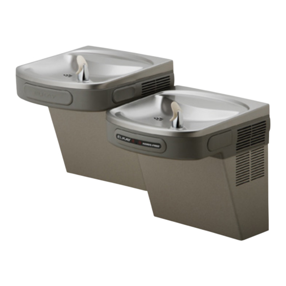
Versatile Cooler Model EZOTL8
configuration as shipped
Versatile Cooler Model EZOTL8
alternate installation
Page 1
1000002687 (Rev. A - 07/18)
Publicité

Sommaire des Matières pour Elkay EZOTL Série
- Page 1 EZOTL8*1H INSTALLATION AND USE MANUAL Manual de instalación y uso Manuel d’installation et utilisation EZOTL Series Versatile Bi-Level Water Coolers ™ ™ EZOTL Serie versátil bi-nivel enfriadores de agua ™ EZOTL Série versatile refroidisseurs d’eau à deux niveaux Versatile Cooler Model EZOTL8 configuration as shipped Versatile Cooler Model EZOTL8 alternate installation...
- Page 2 EZOTL8*1H Note: Danger! Electrical shock hazard. Disconnect power before servicing unit. Nota: peligro! Peligro de descarga eléctrica. Desconecte antes de reparar la unidad l’appareil. Remarque : Danger ! Risque de choc électrique. Débrancher avant de réparer Uses HFC-134A refrigerant Usa refrigerante HFC-134A Utilise du fluide frigorigéne HFC-134A See Figure 5 Vea la Figura 5...
- Page 3 EZOTL8*1H FIG. 2 Page 3 1000002687 (Rev. A - 07/18)
- Page 4 EZOTL8*1H FIG. 3 Page 4 1000002687 (Rev. A - 07/18)
- Page 5 EZOTL8*1H Versatile Wrapper and Trim Kit Installation Instructions Left Hand Wrapper (High Side) Right Hand Wrapper 1) Remove existing wrapper (Low Side) by removing the (4) screws 1) Remove existing wrapper from bottom. by removing the (4) screws 2) Screw trim piece to wrapper from bottom.
-
Page 6: Entretien
EZOTL8*1H HANGER BRACKETS INSTALLATION INSTALACIÓN DE SOPORTES PARA COLGAR SUPPORTS DE CROCHET DE SUSPENSION INSTALLATION Retire el soporte fijador que se encuentra conectado a 1) Remove hanger brackets fastened to back of cooler la parte posterior del enfriador sacando un (1) tornillo. 1) Retirez le support de suspension fixé... -
Page 7: Entretenir Des Instructions
EZOTL8*1H Service Instructions Lower and Upper Shroud To access the refrigeration system and plumbing connections, remove four screws from bottom of cooler to remove the lower shroud. To remove the upper shroud for access to the pushbars, regulator, solenoid valve or other components located in the top of the unit, remove lower shroud, disconnect drain, remove four screws from tabs along lower edge of upper shroud, unplug two wires and water tube. - Page 8 EZOTL8*1H SENSOR RANGE ADJUSTMENT: The electronic sensor used in this cooler is factory pre-set for a “visual” range of 36 inches (914 mm). If actual range varies greatly from this or a different setting is desired, follow the range adjustment procedure below: Using a small tip screwdriver, locate range adjustment screw through the small hole between the sensor lenses (See Page 2.) Turn this screw clockwise to increase range and counterclockwise to decrease range (See Fig.
- Page 9 PRINTED IN U.S.A. INFORMATIONS POUR LE SERVICE PAR NUMERO SANS FRAIS 1-800-260-6640 IMPRESO EN LOS E.E.U.U. IMPRIMÉ AUX É.-U. ELKAY MANUFACTURING COMPANY • 2222 CAMDEN COURT • OAK BROOK, IL 60523 • 630.574.8484 • www.elkay.com Page 9 1000002687 (Rev. A - 07/18)


