Table des Matières
Publicité
Les langues disponibles
Les langues disponibles
Liens rapides
Publicité
Chapitres
Table des Matières
Dépannage

Sommaire des Matières pour hoxter ABRA 6.1
- Page 1 ABRA 6.1 Installations- und Bedienungsanleitung Installation and operating instruction Návod k instalaci a obsluze Manuel d’installation et d’utilisation Installatie- en gebruikershandleiding Instrukcja montażu i obsługi Istruzioni di installazione ed uso...
-
Page 2: Table Des Matières
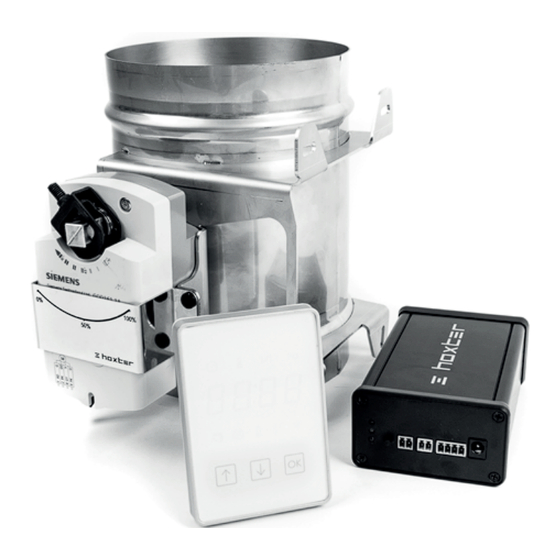
INHALT Seite EINLEITUNG BESCHREIBUNG DES GERÄTES Steuereinheit Display Türkontakt Zuluftklappe Hochtemperaturfühler Stromadapter INSTALLATION Installation des Türkontaktes Installation des Hochtemperaturfühlers Installation der Zuluftklappe Schaltung der Steuereinheit EINSTELLUNG Einstellung des Gerätes und eines Kommunikationskanals Programm STD Programm UNI Programm TEST BETRIEB Informationen auf dem Display Warnmeldungen und Alarm PROBLEME UND IHRE LÖSUNG GARANTIE... -
Page 3: Einleitung
EINLEITUNG Es freut uns sehr, dass Sie sich für unsere Abbrandsteuerung ABRA 6.1 entschieden haben. Der Brennprozess wird mit unserer Regelung durch genaue Dosierung der zugeführten Verbrennungsluft effizienter. Es wird die entsprechende Luftmenge auf Grund der Temperatur im Feuerraum oder in den Zügen zugeführt. -
Page 4: Beschreibung Des Gerätes
BESCHREIBUNG DES GERÄTES STEUEREINHEIT • mit dem Adapter 24V gespeist • Temperaturbeständigkeit der Steuereinheit beträgt Max. 50°C Beschreibung von Eingägen und Kontroll-LED • Die blinkende orange • Eingang für Anschluss LED signalisiert aktive der Zuluftklappe Funkverbindung • Grün leuchtende zwischen dem Display LED signalisiert und Steuereinheit. -
Page 5: Display
TÜRKONTAKT • Fühler mit Anschlussverkabelung; die Temperaturbeständigkeit der Verkabelung beträgt Max. 180°C; die Verkabelung ist 4m lang • magnetisches Gegenstück • Stahlplättchen (ist nur mit den HOXTER Produkten kompatibel) • Schrauben M4x6 für Befestigung des Stahlplättchens und Magnetgegenstücks ZULUFTKLAPPE • Temperaturbeständigkeit der Zuluftklappe aus Edelstahl und deren Komponenten beträgt 50 °C... -
Page 6: Installation
INSTALLATION INSTALLATION DES TÜRKONTAKTES Brechen Sie die perforierte Öffnung im Stahlplättchen aus, ziehen Sie den Fühler des Türkontaktes durch die entstandene Öffnung und befestigen Sie ihn mit der und der Mutter (D). Distanzwalze Befestigen Sie das Stahlplättchen mit dem Fühler mittels mitgelieferten Schrauben auf die bestimmte Stelle im Türrahmen (E). -
Page 7: Installation Des Hochtemperaturfühlers
INSTALLATION DES HOCHTEMPERATURFÜHLERS Führen Sie den Temperaturfühler in die Gewindeöffnung im oberen Teil des Kamineinsatzes/der Grundofentür ein. min. Die minimale Messlänge des Fühlers 20 mm beträgt 20 mm am Ende des Fühlers (H). Der Temperaturfühler muss im Brennraumoder oder im Verbindungsstück zum Schornstein installiert werden. -
Page 8: Einstellung
Teil unten in der Mitte und klappen Sie die Haube auf (siehe Bild). Entfernen Sie das Bändchen unter der Batterie, das die Speisung verhindert und schließen Sie die Haube. Die Abbrandsteuerung ABRA 6.1 ist gleich nach dem Auspacken und Anschließen betriebsbereit. Werkeinstellung ist Kommunikationskanal Ch-1 und Programm Std. -
Page 9: Programm Test
Im nächsten Schritt kann man die aktive Brennphase verlängern oder verkürzen. Es wird der Punkt verstellt, wo die Zuluftklappe schließt – die aktive Brennphase endet und die Glutphase beginnt. Werkseinstellung ist Für die Einstellung gilt: Wert EP 1, 2, ... 6 verlängert die aktive Brennphase Wert EP -1,-2 ... -
Page 10: Betrieb
BETRIEB INFORMATIONEN AUF DEM DISPLAY Aktuelle Informationen werden auf dem Display im Intervall von 5 Sekunden angezeigt. Um die Informationen schneller zu aktualisieren oder das Display aus dem Stand-by-Modus zu wecken, drücken Sie einen Pfeil. Bei laufendem Betrieb werden 3 Grundwerte angezeigt: Aktuelle Temperatur im Feuerraum Die durch den Temperaturfühler im aktuellen Moment gemesse Temperatur... -
Page 11: Warnmeldungen Und Alarm
- erste Position, Klappe voll geöffnet. Diese Phase beginnt mit Öffnen und Schließen der Tür und dauert bis zum Erreichen der Starttemperatur . Die start Starttemperatur ist von dem eingestellten Programm abhängig - zweite Position. Die zweite Phase beginnt wenn die Starttemperatur erreicht wird und dauert mindestens 15 Minuten ab dem Schließen der start Feuerungstür. -
Page 12: Probleme Und Ihre Lösung
PROBLEME UND IHRE LÖSUNG Beseitigung Störung Ursache der Störung Die Einstellung wurde Gehen Sie die nicht gespeichert, oder Einstellung noch Beim Einstellen wird die Funkverbindung einmal durch. auf dem Display „FAIL“ zwischen dem Display angezeigt. und Steuereinheit wurde unterbrochen Stromausfall. Aus Kontrollieren Sie Sicherheitsgründen die Stromversorgung... -
Page 13: Garantie
GARANTIE Die Garantie für die elektronische Abbrandsteuerung ABRA 6.1 und für die dazugehörigen Komponenten beträgt 24 Monate. Die Garantie bezieht sich nicht auf mechanische Beschädigungen und auf Schäden die durch unsachgemäße Handhabung oder auf Grund von zu hohen Temperaturen entstanden sind. Die höchsten zugelassenen Temperaturen sind in der Bedienungseinleitung angegeben. - Page 14 CONTENT Page INTRODUCTION DESCRIPTION OF THE DEVICE Electronic control unit Display Door sensor Air inlet flap Hightemperature sensor Power source adapter INSTALLATION Door sensor installation High-temperature sensor installation Air inlet flap installation Control unit connection SET-UP Setting up the device and communication channel STD program UNI program TEST program...
-
Page 15: Introduction
INTRODUCTION We would like to thank you for purchasing electronic fire-burning control ABRA 6.1. Based on the temperature in the burning chamber this fireburning control optimizes combustion by precise control of inlet air. The installation of this product must be carried out by a specialist –... -
Page 16: Description Of The Device
DESCRIPTION OF THE DEVICE ELECTRONIC FIREBURNING CONTROL UNIT • Power adapter 24V • Heat resistance max 50°C / 122°F Description of inputs and control diode • The orange blinking • Connector input light indicates for air inlet flap the ongoing •... -
Page 17: Display
• Sensor with connecting cable, length 4 m / 13 ft., heat resistance of the cable 180°C / 356°F • Magnetic counterpart • Metal holder (only compatible with HOXTER products) • M4x6 screws to attach the door sensor holder and the magnetic counterpart AIR INLET FLAP •... -
Page 18: Installation
INSTALLATION DOOR SENSOR INSTALLATION Break out the indicated opening in the sensor holder (B), pull the door sensor through this hole and fasten with the distance barrel and a nut (D). Attach the door sensor with the holder using the supplied screws to the designed place on the doorframe (E). -
Page 19: High-Temperature Sensor Installation
HIGH TEMPERATURE SENSOR INSTALLATION Screw the high temperature sensor into the designed opening on the fireplace insert or the stove doors. min. Minimal lenght for correct measurment 20 mm is 20mm / 0.8 in at its end (H). The temperature sensor must be installed in the combustion chamber or in the connection to the chimney. -
Page 20: Set-Up
(see figure) Remove the strip between the battery and the contact and close the cover. ABRA 6.1 is ready for use right after unpacking and Ch-1 plugging it in. The communication channel and program are set by default. -
Page 21: Test Program
It is possible to shorten / extend the active burning phase in the next step. Selecting a different value changes the point, when the air flap closes completely – active burning ends and the glowing phase of hot coal begins. The default value is The values that can be set-up: Values EP 1, 2, ... -
Page 22: Informations On Display
Burning time Begins with closing the door. Air flap positions / burning phases The ABRA 6.1 control doesn’t regulate the burning process in intervals with fixed time for each phase. This is due to varying burning conditions (humidity, firewood quantity, chimney draft etc.) The length... -
Page 23: Low Battery
- first position. This phase begins when the fire chamber door is opened and closed and ends when the starting temperature is reached. The starting start temperature depends on the program that is set-up. - second position. The second phase begins when the starting temperature is reached and lasts at least 15 minutes after closing the door. -
Page 24: Troubleshooting
TROUBLESHOOTING Failure Cause Solution Problem when Repeat the set-up „FAIL“ appears on the saving the settings or process from the display during the set- communication failure beginning. up process. during the setting. Power failure. For Check the power safety reasons supply of the control the air flap opens unit. -
Page 25: Warranty
WARRANTY Warranty for the electronic fireburning control ABRA 6.1 and its componenst is 24 months. The warranty doesn’t cover mechanical damages, damages caused by improper handling and damages caused by exposure of components to temperatures higher than their defined maximum. - Page 26 OBSAH Strana ÚVOD POPIS ZAŘÍZENÍ Řídící jednotka elektronické regulace Displej Dveřní kontakt Klapka přívodu vzduchu Vysokoteplotní čidlo Napájecí adaptér INSTALACE Instalace dveřního kontaktu Instalace vysokoteplotního čidla Instalace klapky přívodu vzduchu Zapojení jednotky regulace NASTAVENÍ Nastavení produktu a komunikačního kanálu Režim STD Režim UNI Režim TEST PROVOZ...
-
Page 27: Úvod
ÚVOD Děkujeme za zakoupení elektronické regulace Hoxter ABRA 6.1. Tato regulace optimalizuje proces hoření přesným dávkováním množství spalovacího vzduchu na základě průběhu teploty v ohništi nebo spalinové cestě. Instalaci tohoto zařízení musí provádět odborník – kamnář. Před použitím regulace si prosím přečtěte návod k instalaci... -
Page 28: Popis Zařízení
POPIS ZAŘÍZENÍ ŘÍDÍCÍ JEDNOTKA ELEKTRONICKÉ REGULACE • Napájení zdrojem 24V • Teplotní odolnost max. 50° Popis vstupů a kontrolních diod • Oranžově blikající • Vstup pro připojení kontrolka signalizuje klapky přívodu probíhající komunikaci vzduchu mezi řídící jednotkou a • Zeleně svítící kontrolka displejem signalizuje probíhající... -
Page 29: Displej
• Čidlo s připojovacím kabelem v délce 4m, tepelná odolnost kabelu 180°C • Protikus s magnetem • Ocelová úchytka pro dveřní kontakt (kompatibilita pouze s produkty HOXTER) • Šroubky M4x6 pro připevnění úchytky a protikusu KLAPKA PŘÍVODU VZDUCHU • Tepelná odolnost nerezové klapky a jejich komponentů... -
Page 30: Instalace
INSTALACE INSTALACE DVEŘNÍHO KONTAKTU Vylomte předpálený otvor v ocelové úchytce (B), otvorem prostrčte čidlo dveřního kontaktu a v případě potřeby připevněte pomocí vymezovacího válečku (C), viz bod 4 a matice (D). Pomocí přiložených šroubků upevněte ocelovou úchytku s čidlem na určené místo v rámu dvířek (E). -
Page 31: Instalace Vysokoteplotního Čidla
INSTALACE VYSOKOTEPLOTNÍHO ČIDLA Vysokoteplotní čidlo zašroubujte na krbovou vložku / kamnová dvířka na místo k tomu určenému. min. Minimální měřící délka čidla 20 mm je 20mm na jeho konci (H). Čidlo musí být nainstalováno ve spalovací komoře nebo napojení do komína. Pro správnou funkčnost nemůže být čidlo nainstalováno za akumulačním tahem nebo akumulačními prstenci. -
Page 32: Nastavení
Pro řístup k bateriím jednotky dipleje stlačte bílý kryt ve spodní části uprostřed a otevřete (viz obrázek). U baterií displeje odstraňte lístek přerušující jeho napájení a kryt zaklapněte zpět. Produkt ABRA 6.1 je připraven k používání ihned po vybalení a zapojení. Standartně je nastaven komunikační kanál Ch-1 a režim hoření... -
Page 33: Režim Test
V dalším kroku můžete prodloužit či zkrátit aktivní fázi hoření. Nastavením měníte bod, kdy se zcela uzavírá klapka přívodu vzduchu, končí aktivní fáze dohořívání a začíná fáze žhavého uhlí. Výchozí hodnota je Pro nastavení pak platí: Hodnoty EP 1, 2, ... 6 prodlužují aktivní fázi dohořívání Hodnoty EP -1,-2,...-6 zkracují... -
Page 34: Provoz
Začíná okamžikem zavřením dvířek (spojením dveřního kontaktu). Pozice klapky neboli fáze hoření Regulace ABRA 6.1 nereguluje proces hoření pevně nastavenými časovými intervaly pro jednotlivé stupně. Je to z důvodu nestálých podmínek při hoření (vlhkost a množství paliva, tah komínu). Délka a průběh spalovacího procesu... -
Page 35: Upozornění A Alarmy
- první pozice. Tato fáze začíná otevřením a opětovným zavřením dvířek a končí dosažením startovací teploty start Startovací teplota je závislá na volbě konkrétního režimu. - druhá pozice. Druhá fáze začíná po dosažení startovací teploty a trvá minimálně 15 minut od zavření dvířek. start V této fázi je dosažena maximální... -
Page 36: Řešení Problémů
ŘEŠENÍ PROBLÉMŮ Závada Příčina Odstranění Problém při ukládání Zopakujte nastavení Při nastavování režimu nastavení nebo produktu. se na displeji zobrazí výpadek komunikace. “FAIL”, Výpadek proudu. Zkontrolujte napájení Klapka se z řídící jednotky. bezbečnostních důvodů plně otevře. Displej je mimo Snižte vzdálenost mezi dosah jednotky. -
Page 37: Garance
GARANCE Záruční doba na elektronickou regulaci ABRA 6.1 a její komponenty je 24 měsíců. Záruka se nevztahuje na mechanické poškození, poškození z důvodu vystavení komponentů teplotám vyšším než jejich definovaným maximálním hodnotám a poškození vzniklá neodbornou manipulaci v rozporu s návodem. - Page 38 TABLE DES MATIÈRES Page INTRODUCTION DESCRIPTION DE L’ APPAREIL Régulateur électronique de combustion Afficheur Capteur de Porte Volet d’arrivée d’air Sonde thermique Adaptateur électrique INSTALLATION Installation du capteur de porte Installation de la sonde thermique Installation du volet d’arrivée d’air Raccordement du régulateur RÉGLAGE Réglage du produit et du canal de communication...
-
Page 39: Introduction
INTRODUCTION Merci d’avoir acheté le régulateur électronique de combustion ABRA 6.1. Celui-ci optimise la combustion grâce à un contrôle précis de l’arrivée d’air en fonction de la température dans la chambre de combustion. Cet appareil ne peut être installé que par un spécialiste (fabricant de poêles). -
Page 40: Description De L' Appareil
DESCRIPTION DE L’ APPAREIL RÉGULATEUR ÉLECTRONIQUE DE COMBUSTION • Adaptateur électrique 24 V • Résistance à la chaleur max. 50 °C Description des entrées et des DEL de contrôle • Le voyant clignotant • Entrée pour raccorder orange indique que le volet d’arrivée d’air le régulateur est en •... -
Page 41: Afficheur
à la chaleur du câble 180°C / 356°F • Contre-pièce magnétique • Plaquette de support métallique (uniquement compatible avec les produits de HOXTER) • Vis M 4x6 pour fixer la plaquette de support métallique à la contre-pièce magnétique VOLET D’ARRIVÉE D’AIR •... -
Page 42: Installation
INSTALLATION INSTALLATION DU CAPTEUR DE PORTE Brisez l‘ouverture perforée dans la plaquette de support métallique (B), introduisez le capteur de porte dans l’ouverture et fixez-le et l’écrou (D). avec l’anneau d’écartement Fixez la plaquette de support métallique et le capteur à l’endroit indiqué sur le cadre de la porte avec les vis fournies. -
Page 43: Installation De La Sonde Thermique
INSTALLATION DE LA SONDE THERMIQUE Vissez la sonde thermique dans le trou fileté de la partie supérieure du foyer encastrable ou de la porte du poêle. min. L’extrémité de la sonde doit 20 mm ressortir au moins de 20 mm (H). La sonde thermique doit être installée dans la chambre de combustion ou le raccord à... -
Page 44: Réglage
(voir illustration). Enlevez la bande entre les piles et le contact et refermez le boîtier. Le régulateur ABRA 6.1 est prêt à l’emploi quand il est déballé et branché. Le canal de communication Ch-1 et le programme sont réglés par défaut. -
Page 45: Programme Test
L’étape suivante permet de modifier la durée de la phase de combustion. Cela permet de modifier le moment où le volet d’arrivée d’air se ferme complètement – la phase de combustion s’arrête et la phase d’incandescence commence. La valeur par défaut est Les réglages sont les suivants : Les valeurs EP 1, 2, ... -
Page 46: Utilisation
Elle commence quand on ferme la porte. Position du volet d’arrivée d’air et phase de combustion Le régulateur ABRA 6.1 ne règle pas la combustion par durées fixes pour chaque phase, car les conditions peuvent varier (humidité, quantité de bois, tirage de la cheminée, etc.). -
Page 47: Alarme Et Messages D'avertissement
- première position Cette phase commence quand la porte de la chambre de combustion est ouverte et refermée. Elle finit quand la température de départ Tstart est atteinte. La température de départ dépend du programme sélectionné. - deuxième position La deuxième phase commence quand la température de départ Tstart est atteinte et dure au moins 15 minutes après la fermeture... -
Page 48: Dépannage
DÉPANNAGE Panne Cause Solution Problème lors de Recommencez le la sauvegarde des réglage du début. « FAIL » s’affiche lors réglages ou échec du réglage. de la communication pendant le réglage. Panne de courant. Contrôlez Pour des raisons l’alimentation de sécurité, le volet électrique du d’arrivée d’air s’ouvre régulateur. -
Page 49: Garantie
GARANTIE La garantie pour le régulateur électronique de combustion ABRA 6.1 et ses composants s’élève à 24 mois. La garantie ne couvre pas les dommages mécaniques, les dommages dus à une mauvaise manipulation et les dommages causés par une exposition des composants à des températures supérieures aux températures maximales indiquées. - Page 50 Inhoudstafel Pagina INLEIDING BESCHRIJVING VAN HET TOESTEL Elektronische bedieningseenheid voor kachels Scherm Deursensor Luchtinlaatklep Sensor voor hoge temperaturen Stroomadaptor INSTALLATIE Installatie deursensor Installatie sensor voor hoge temperaturen Installatie Luchtinlaatklep Verbinding bedieningseenheid INSTELLEN Het product en communicatiekanaal instellen STD-programma UNI programma Testprogramma BEDIENING Informatie op het scherm...
-
Page 51: Inleiding
INLEIDING We willen u van harte bedanken voor de aankoop van de elektronische bedieningseenheid ABRA 6.1 voor uw kachel. Op basis van de temperatuur in uw verbrandingskamers optimaliseert deze bedieningseenheid de verbranding door middel van een nauwkeurig gecontroleerde luchtinlaat. De installatie van dit toestel mag enkel worden uitgevoerd door een kachelspecialist. -
Page 52: Beschrijving Van Het Toestel
BESCHRIJVING VAN HET TOESTEL ELEKTRONISCHE BEDIENINGSEENHEID VOOR KACHELS • Stroomadapter 24 V • Hittebestendigheid max. 50°C Beschrijving van ingangen en controlediode • Het oranje knipperende • Aansluitpunt voor lampje geeft de luchtinlaatklep voortdurende • Het groene communicatie controlelampje geeft aan tussen het aan dat de luchtklep bedieningspaneel en van positie verandert... -
Page 53: Scherm
• Sensor met verbindingskabel, lengte 4 m, hittebestendigheid van de kabel 180°C (A) • Magnetische tegenhanger (B) • Metalen houder (enkel compatibel met HOXTER-producten) (C) • M4x6-schroeven om de deursensorhouder en de magnetische tegenhanger te bevestigen LUCHTINLAATKLEP • Hittebestendigheid van de inox klep en de onderdelen ervan max. 50°C •... -
Page 54: Installatie
INSTALLATIE INSTALLATIE DEURSENSOR Druk de aangegeven opening door de sensorhouder (B), trek de deursensor door het gat en bevestig met het afstandsstuk en een moer (D). Bevestig de deursensor aan de houder met behulp van de meegeleverde schroeven op de aangegeven plaats in het deurkader (E). Bevestig de magnetische tegenhanger aan de onderste rand van de deur. -
Page 55: Installatie Sensor Voor Hoge Temperaturen
INSTALLATIE SENSOR VOOR HOGE TEMPERATUREN Schroef de sensor voor hoge temperaturen in de aangegeven opening op de cassette van de open haard of de kacheldeuren. min. 20 mm Minimale lengte voor correcte meting is 20 mm op het uiteinde (H). De temperatuursensor moet in de verbrandingskamer of in de verbinding met de schoorsteen worden geïnstalleerd. -
Page 56: Instellen
(zie afbeelding) om bij de batterijen van het scherm te kunnen. Verwijder de strip tussen de batterij en het contact en sluit de behuizing. ABRA 6.1 is klaar voor gebruik na het uitpakken en aansluiten. Het communicatiekanaal Ch-1 en programma zijn standaard ingesteld. -
Page 57: Testprogramma
Het is mogelijk om de actieve verbrandingsfase te verlengen of in te korten in de volgende stap. Door een andere waarde te selecteren, wijzigt het moment waarop de luchtinlaatklep volledig wordt gesloten. Zo stopt de actieve verbrandingsfase en begint de gloeifase van de hete kolen. De standaardwaarde is De waarden kunnen worden ingesteld: EP-waarden EP 1, 2, ... -
Page 58: Bediening
Verbrandingstijd Begint wanneer de deur wordt gesloten. Posities luchtklep / verbrandingsfases De ABRA 6.1-bediening regelt het verbrandingsproces niet per interval met een ingestelde tijdspanne per fase. Dit is te wijten aan variërende verbrandingsomstandigheden (vochtigheid, hoeveelheid brandhout, schoorsteentrek, enz.). -
Page 59: Alarmen En Waarschuwingsberichten
- eerste positie. Deze fase vangt aan wanneer de kacheldeur wordt geopend en gesloten en eindigt wanneer de begintemperatuur Tstart is bereikt. De begintemperatuur hangt af van het programma dat is ingesteld. - tweede positie. De tweede fase begint wanneer de begintemperatuur Tstart is bereikt en duurt minstens 15 minuten nadat de deur werd gesloten. -
Page 60: Probleemoplossing
PROBLEEMOPLOSSING Storing Oorzaak Oplossing Probleem bij het Herhaal het ‘FAIL’ verschijn op het opslaan van de instellingsproces scherm tijdens het instellingen of van bij het begin. instellingsproces. communicatiestoring tijdens de instelling. Stroomstoring Om Controleer de veiligheidsredenen stroomtoevoer van opent de luchtklep de bedieningseenheid. -
Page 61: Garantie
GARANTIE Garantie voor de elektronische bedieningseenheid ABRA 6.1 voor kachels en de onderdelen ervan bedraagt 24 maanden. De garantie dekt geen mechanische schade, schade die wordt veroorzaakt door slechte handelingen en schade die wordt opgelopen doordat onderdelen worden blootgesteld aan temperaturen hoger dan hun gedefinieerde maximum. - Page 62 SPIS TREŚCI Strona WSTĘP OPIS URZĄDZENIA Jednostka sterująca regulacji elektronicznej Wyświetlacz Kontakt drzwiowy Klapa dopływu powietrza Czujnik wysokotemperaturowy Adapter zasilania MONTAŻ Montaż kontaktu drzwiowego Montaż czujnika wysokotemperaturowego Montaż klapy dopływu powietrza Podłączenie jednostki regulacji USTAWIENIA Ustawienia produktu i kanału komunikacyjnego Tryb STD Tryb UNI Tryb TEST...
-
Page 63: Wstęp
WSTĘP Dziękujemy za zakup elektronicznej regulacji Hoxter ABRA 6.1. Regulacja rejestruje przebieg temperatur w palenisku lub w kominie i na podstawie tego doprowadza odpowiednią ilość powietrza, co wpływa na optymalizację procesu spalania. Montaż urządzenia może przeprowadzić wyłącznie wykwalifikowany specjalista – zdun. -
Page 64: Opis Urządzenia
OPIS URZĄDZENIA JEDNOSTKA STERUJĄCA REGULACJI ELEKTRONICZNEJ • Źródło zasilania 24V • Odporność termiczna maks. 50 °C Opis wejść i diod kontrolnych • Kontrolka migająca • Wejście do podłączenia na pomarańczowo klapy dopływu sygnalizuje przebieg powietrza komunikacji • Kontrolka świecąca na zielono sygnalizuje przebieg zmiany pozycji klapy ABRA 6. -
Page 65: Wyświetlacz
• Czujnik z kablem przyłączeniowym o długości 4m, odporność termiczna kabla 180°C • Przeciwkształtka z magnesem • Uchwyt stalowy do kontaktu drzwiowego • (kompatybilność tylko z produktami HOXTER) • Śruby M4x6 do mocowania uchwytu i przeciwkształtki KLAPA DOPŁYWU POWIETRZA • Odporność termiczna klapy nierdzewnej i jej komponentów maks. -
Page 66: Montaż
MONTAŻ MONTAŻ KONTAKTU DRZWIOWEGO Wyłamać wstępnie wypalony otwór w uchwycie stalowym (B), włożyć do otworu czujnik kontaktu drzwiowego i w razie potrzeby przymocować za pomocą wałka i nakrętki (D), zob. punkt 4. ograniczającego Przy pomocy dołączonych śrub przymocować stalowy uchwyt z czujnikiem w wyznaczonym miejscu w ramie drzwiczek (E). -
Page 67: Montaż Czujnika Wysokotemperaturowego
MONTAŻ CZUJNIKA WYSOKOTEMPERATUROWEGO Przykręcić czujnik wysokotemperaturowy do wkładu kominkowego / drzwiczek piecowych w wyznaczonym do tego miejscu. min. Minimalna długość pomiaru czujnika 20 mm wynosi 20mm na jego końcu (H).. Czujnik musi być zamontowany w komorze spalania lub w miejscu podłączenia do komina. -
Page 68: Ustawienia
(zob. rysunek). Usunąć ochronę blokującą zasilanie baterii i zatrzasnąć ponownie osłonę. Produkt ABRA 6.1 jest gotowy do eksploatacji natychmiast po rozpakowaniu i podłączeniu. Standardowo ustawiony jest kanał komunikacyjny Ch-1 i tryb spalania standard Std. Tryb standard jest odpowiedni dla wkładów kominkowych Hoxter... -
Page 69: Tryb Test
Następnie można przedłużyć lub skrócić aktywną fazę palenia. Poprzez ustawienia zmienia się punkt całkowitego zamknięcia klapy dopływu powietrza, następuje koniec aktywnej fazy dopalania i początek fazy rozżarzonego węgla. Wartość wyjściowa wynosi Opis ustawień: Wartości EP 1, 2, ... 6 przedłużają aktywną fazę dopalania Wartości EP -1,-2,...-6 skracają... -
Page 70: Eksploatacja
Czas palenia Zaczyna biec w momencie zamknięcia drzwiczek (połączenie kontaktu drzwiowego). Pozycja klapy lub faza spalania Regulacja ABRA 6.1 nie reguluje procesu palenia na podstawie ustawionych na stałe interwałów czasowych dla poszczególnych stopni. Wynika to ze zmiennych warunków podczas spalania (wilgotność... -
Page 71: Ostrzeżenia I Alarmy
- pozycja pierwsza. Ta faza rozpoczyna się otwarciem i ponownym zamknięciem drzwiczek, kończy zaś osiągnięciem temperatury startowej start Temperatura startowa jest uzależniona od wyboru konkretnego trybu. - pozycja druga. Faza druga rozpoczyna się po osiągnięciu temperatury startowej Tstart i trwa minimalnie 15 minut od zamknięcia drzwiczek. W tej fazie zostaje osiągnięta maksymalna temperatura w palenisku - pozycja trzecia. -
Page 72: Rozwiązywanie Problemów
ROZWIĄZYWANIE PROBLEMÓW Usterka Przyczyna Usunięcie problemu Podczas ustawiania Problem przy Powtórzyć ustawienia trybu na wyświetlaczu zapisywaniu ustawień produktu. pojawia się lub awaria komunikacji. “FAIL”. Awaria prądu. Klapa Sprawdzić zasilanie otworzy się całkowicie jednostki sterującej. ze względów bezpieczeństwa. Wyświetlacz jest poza Zmniejszyć... -
Page 73: Gwarancja
GWARANCJA Okres gwarancji na regulację elektroniczną ABRA 6.1 i jej komponenty wynosi 24 miesiące. Gwarancja nie obejmuje uszkodzeń mechanicznych, uszkodzeń komponentów powstałych wskutek temperatur wyższych od ich zdefiniowanych wartości maksymalnych oraz uszkodzeń powstałych wskutek niewłaściwej manipulacji niezgodnie z instrukcją. Montaż regulacji elektronicznej ABRA 6.1 musi zostać przeprowadzony przez specjalistę... - Page 74 INDICE Pagina INTRODUZIONE DESCRIZIONE DEL DISPOSITIVO Centralina elettronica Display Sensore porta Serranda ingresso aria Termocoppia ad alta temperatura Alimentatore INSTALLAZIONE Installazione sensore porta Installazione termocoppia ad alta temperatura Installazione serranda ingresso aria Connessione centralina elettronica CONFIGURAZIONE Configurazione dispositivo e canali di comunicazione Programma STD Programma UNI Programma TEST...
-
Page 75: Introduzione
INTRODUZIONE Grazie per aver scelto una centralina di controllo elettronico della combustione ABRA 6.1. Sulla base della temperatura rilevata in camera di combustione, questa centralina ottimizza la combustione con un controllo accurato dell’aria comburente. L’installazione di questo prodotto deve essere eseguita esclusivamente da personale esperto –... -
Page 76: Descrizione Del Dispositivo
DESCRIZIONE DEL DISPOSITIVO CENTRALINA DI CONTROLLO ELETTRONICO DELLA COMBUSTIONE • alimentatore 24V • resistenza al calore max 50°C Descrizione led di trasmissione e controllo • la luce intermittente • connettore serranda arancione indica la ingresso aria comunicazione in corso • la spia luminosa verde tra la centralina e il indica che la serranda display. -
Page 77: Display
• sensore con cavo di connessione, lunghezza 4 m, resistenza del cavo al calore 180°C • magnete • supporto metallico (compatibile solo con prodotti HOXTER) • viti M4x6 per connettere il supporto del sensore porta al magnete SERRANDA INGRESSO ARIA •... -
Page 78: Installazione
INSTALLAZIONE INSTALLAZIONE DEL SENSORE PORTA Forare l’apertura indicata nel supporto del sensore (B), far passare il sensore porta attraverso questo foro e fissare con il cilindro distanziatore e un dado Fissare il sensore porta con il supporto posizionato nel profilo della porta (E), usando le viti fornite Fissare il magnete al bordo inferiore della porta Sia il sensore porta che il magnete devono... -
Page 79: Installazione Termocoppia Ad Alta Temperatura
INSTALLAZIONE DELLA TERMOCOPPIA AD ALTA TEMPERATURA Avvitare la termocoppia ad alta temperatura nell’apertura predisposta sull’inserto o sulla porta min. La lunghezza minima per una corretta 20 mm rilevazione è di 20 mm alla sua estremità La termocoppia deve essere installata nella camera di combustione o nel collegamento alla canna fumaria. -
Page 80: Configurazione
(vedi figura). Rimuovere la striscia tra la batteria e il contatto e richiudere la cover. ABRA 6.1 è pronto per l’uso non appena verrà rimosso l’imballo e inserita la spina. Il canale di Ch-1... -
Page 81: Programma Test
E’ possibile ridurre / estendere la fase attiva di combustione nel prossimo step. Selezionando un valore diverso cambia il punto in cui la serranda ingresso aria chiude completamente, la fase attiva di combustione termina e la fase con le braci vive inizia. Il valore di default è Valori che possono essere impostati: Valori EP 1, 2, ... -
Page 82: Funzionamento
Tempo di combustione Inizia con la chiusura della porta. Posizioni serranda / fasi di combustione La centralina Abra 6.1 non regola il processo di combustione con intervalli di tempo prefissato per ciascuna fase. Ciò è dovuto a condizioni di combustione variabili (umidità, quantità di legna, tiraggio del camino, etc.). -
Page 83: Allarmi E Avvisi
- Prima posizione. Questa fase inizia quando la porta della camera di combustione viene aperta e chiusa e termina quando viene raggiunta la temperatura di avvio La temperatura di avvio dipende dal START. programma impostato. - Seconda posizione. La seconda fase inizia quando viene raggiunta la temperatura di avvio e viene mantenuta per almeno 15 minuti dopo la START... -
Page 84: Risoluzione Problemi
RISOLUZIONE PROBLEMI Problema Motivo Soluzione Problema durante Ripetere il il salvataggio procedimento di Compare “FAIL” sul delle impostazioni configurazione display durante la fase o mancanza di dall’inizio. di configurazione. comunicazione durante la configurazione. Calo di tensione. Per Controllare motivi di sicurezza l’alimentazione della la serranda si apre centralina. -
Page 85: Garanzia
GARANZIA La garanzia per il controllo elettronico di combustione ABRA 6.1 e i suoi componenti è di 24 mesi. La garanzia non copre danni meccanici, danni causati da un uso improprio e danni causati da un’esposizione dei componenti a temperature superiori a quelle massime consentite. - Page 86 NOTIZEN / NOTES / POZNÁMKY / REMARQUES / OPMERKINGEN / NOTATKI / NOTE...
- Page 87 NOTIZEN / NOTES / POZNÁMKY / REMARQUES / OPMERKINGEN / NOTATKI / NOTE...
- Page 88 HOXTER GmbH HOXTER a.s. Hersbrucker Straße 23 Jinačovice 509 91244 Reichenschwand 664 34 Jinačovice Germany Czech republic +49 (0)9151 8659 163 +420 518 777 701 info@hoxter.de info@hoxter.eu www.hoxter.de www.hoxter.eu...