Table des Matières
Publicité
Les langues disponibles
Les langues disponibles
Liens rapides
Publicité
Table des Matières

Manuels Connexes pour CDVI Wiegand KCPROXWLC


Sommaire des Matières pour CDVI Wiegand KCPROXWLC
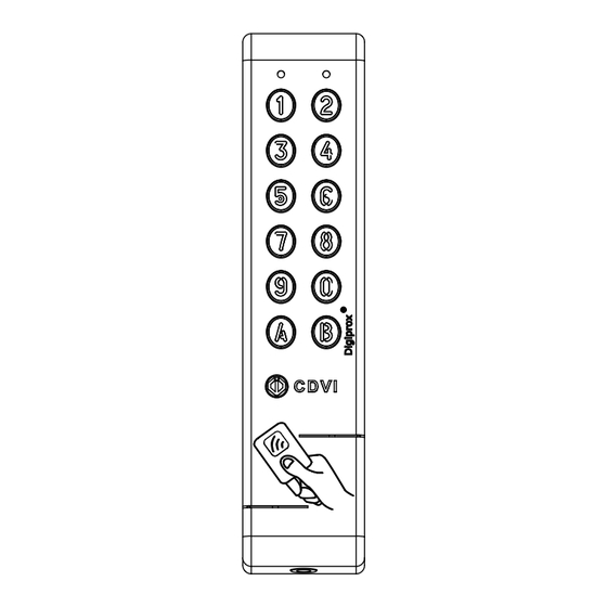
- Page 1 FRANCAIS ENGLISH KCPROXWLC Lecteur double technologie Proximité/Digicode - Wiegand ® Dual Technology Digicode /Proximity Reader - Wiegand ® Range: Integrated Access Control / Gamme : Contrôle d’Accès Intégré INSTALLATION MANUAL MANUEL D’INSTALLATION MANUEL D’INSTALLATION Group Products...
-
Page 2: Product Presentation
- Make sure not to exceed 50 meters between power supply should be certified EN60950-1:2006/ the INTBUSW reader interface and the KCPROXWLC A11:2009 standards and should be designed to be Pin/Prox Digicode ® a low power supply source. cdvi.com cdvigroup.com... -
Page 3: Mounting Kit
R1/D1 WHITE DATA 1 DATA R2/D1 BLUE CLOCK CLOCK STANDARD – 1 WIRE 8 ou 18 PURPLE PROGRAMMING PROGRAMMING PROGRAMMING OUT1 YELLOW GREEN LED GREEN LED GREEN LED OUT3 OUT2 ORANGE RED LED RED LED RED LED OUT4 cdvi.com cdvigroup.com... -
Page 4: Input Voltage Selection
Strike Magnet Varistor Input voltage selection Two different configurations, are possible: Shielded 12VDC only cable (As standard) Cut the strap 12VAC or 24VDC Door contact (not used) To other door controllers Connect E and M (INTBUSW) cdvi.com cdvigroup.com... - Page 5 - Dip4 = ON - PDN345BUSPROX DIP SWITCH adressing Mode Front plate - Address programming during installation - Dip4 = OFF Reader 1 Reader 2 Reader 3 ST1 (Programming jumper) Reader 4 ST1 (Programming jumper) : Normal Normal (As standard) Installation cdvi.com cdvigroup.com...
-
Page 6: Programming Chart
1 beep = OK 1 beep = OK 1 beep = OK Green LED ON Green LED ON Green LED ON Green LED ON 4 beeps = Error 4 beeps = Error 4 beeps = Error 4 beeps = Error cdvi.com cdvigroup.com... - Page 7 Green LED ON 4 beeps = Error 4 beeps = Error 4 beeps = Error For the programming connect the purple cable with the black cable. Switch the power supply off then switch it on. 2 beeps are emitted cdvi.com cdvigroup.com...
- Page 8 2. Press A1 to enter in the output format menu: - The Green LED is lighting up during 1 second. - One beep is emitted. - Enter 26, 30 or 44 to define the bit format. * Refer to the chapter «Entry in programming». cdvi.com cdvigroup.com...
- Page 9 - The Green LED is lighting up during 1 second. LED off. The Buzzer and LED intputs are activated. 9] 26-BIT WIEGAND FORMAT Chronograms 0 logic 1 logic \DATA1 \CLOCK \DATA0 μs μs * Refer to the chapter «Entry in programming». cdvi.com cdvigroup.com...
- Page 10 30-bit wiegand (Signal: DATA1, DATA0 and CLOCK) and is structured as follow: - Parity 1: 1 bit – even parity for the first 14-bit. Code : A code is formed from 7 half byte. Each byte is transferred from bit 7 to bit 0. cdvi.com cdvigroup.com...
- Page 11 KEYPAD + BADGE CODES Example: Badge 0F01198AAD + 6-DIGIT Keypad code: « 6 7 1 3 7 5 » Then « B » 0000 1111 0000 0001 0001 1001 1000 1010 1010 1101 BADGE Decimal KEYPAD CODE Hexadécimal cdvi.com cdvigroup.com...
- Page 12 - In 5-digits > 00012345 - In 6-digits > 00123456 /Présence /Data /Clock Each digit is made of 5 bits: 4 bits data + 1 bit parity Characters Parity B = SS D = FD F = ES cdvi.com cdvigroup.com...
- Page 13 14] NOTES ................................................................................................................................................................................................................................................................................................................................................................................................................................................................................................................................................................................................................................................................................................................................................................................................................................................................................................................................................................................................................................................................................................................................................. cdvi.com cdvigroup.com...
-
Page 14: Lecteur Double Technologie Proximité/Digicode
EN60950-1 :2006/A11 de porte (INTBUSW) peut atteindre 1200 m maximum. :2009 et construite pour être une alimentation - Attention de ne pas passer vos fils à proximité limitée en puissance. de câbles «Courant fort» (ex: 230 V AC). cdvi.com cdvigroup.com... -
Page 15: Kit De Montage
R1/D1 BLANC DATA 1 DATA R2/D1 BLEU CLOCK CLOCK STANDARD – 1 WIRE 8 ou 18 VIOLET PROGRAMMATION PROGRAMMATION PROGRAMMATION OUT1 JAUNE VOYANT VERT VOYANT VERT VOYANT VERT OUT3 OUT2 ORANGE VOYANT ROUGE VOYANT ROUGE VOYANT ROUGE OUT4 cdvi.com cdvigroup.com... -
Page 16: Alimentation
: 12 V DC uniquement (Configuration usine) Coupez le strap 12 V AC ou 24 V DC Si vous ne souhaitez pas de gestion de l’etat Vers d’autres contrôleur porte : Relier E et M de portes (INTBUSW) cdvi.com cdvigroup.com... - Page 17 - PDN345BUSPROX Adressage DIPSWITCH Mode Façade - Programmation de l’adresse par installation - Dip4 = OFF Lecteur 1 Lecteur 2 Lecteur 3 ST1 (Cavalier de programmation) Lecteur 4 ST1 (Cavalier de programmation) : Normal Normal (Config. usine) Installation cdvi.com cdvigroup.com...
-
Page 18: Programmation
1 bip = OK 1 bip = OK 1 bip = OK LED verte ON LED verte ON LED verte ON LED verte ON (4 bips = Erreur) (4 bips = Erreur) (4 bips = Erreur) (4 bips = Erreur) cdvi.com cdvigroup.com... - Page 19 1 bip = OK LED verte ON LED verte ON LED verte ON (4 bips = Erreur) (4 bips = Erreur) (4 bips = Erreur) Déconnexion du câble Violet et noir pour sortir de la programmation 2 bips sonores cdvi.com cdvigroup.com...
- Page 20 2. Tapez A3 pour la saisie du nombre 2. Tapez A1 pour choisir le format de sortie : de bits du code Wiegand : - Un bip est émis. * Référez-vous à la procédure d’entrée en programmation en début de chapitre. cdvi.com cdvigroup.com...
- Page 21 - La Led verte s’allume pendant 1 seconde. 3. Séparer le fil violet du fil noir : Deux bips sont émis pour confirmer le retour au mode normal de fonctionnement. * Référez-vous à la procédure d’entrée en programmation en début de chapitre. cdvi.com cdvigroup.com...
- Page 22 Parité 2 Hexadécimal Parité 1 Parité 2 - Parité 1 : «0» si le nombre de 1 dans bit 2 à bit 13 est paire, «1» si le nombre de 1 dans bit 2 à bit 13 est impaire. cdvi.com cdvigroup.com...
- Page 23 - La communication s’effectue par une liaison de type Wiegand 44 bits ( Signaux: DATA1, DATA0 et CLOCK). La trame est constituée d’une totalité de 30 bits et se décompose comme suit : Bit 1 à bit 40 Bit 41 à bit 44 Code badge cdvi.com cdvigroup.com...
- Page 24 (y compris SS et ES) Le nombre de caractères est fixé à 8 : - En 4 termes – 00001234, - En 5 termes – 00012345, - En 6 termes - 00123456. /Présence /Data /Clock cdvi.com cdvigroup.com...
- Page 25 Chaque caractère est composé de 5 bits : 4 bits de données + 1 bit de parité. Caractères Parité B = SS D = FD F = ES 14] NOTES ............................................................................................................................................................................................................................................................................................................................................................................................................................................................................................. cdvi.com cdvigroup.com...
- Page 26 ......................................................................................................................................................................................................................................................................................................................................................................................................................................................................................................................................................................................................................................................................................................................................................................................................................................................................................................................................................................................................................................................................................................................................................................cdvi.com cdvigroup.com...
- Page 27 ......................................................................................................................................................................................................................................................................................................................................................................................................................................................................................................................................................................................................................................................................................................................................................................................................................................................................................................................................................................................................................................................................................................................................................................cdvi.com cdvigroup.com...
- Page 28 Reference : G0301FR0334V05 Extranet : EXE-CDVI_IM KCPROXWLC CMYK A5 EN-FR 05 Creator of electronic access solutions *G0301FR0334V05* CDVI Group FRANCE (Headquarter/Siège social) Phone: +33 (0)1 48 91 01 02 Fax: +33 (0)1 48 91 21 21 CDVI CDVI CDVI CDVI UK...