Publicité
Les langues disponibles
Les langues disponibles
Liens rapides
All manuals and user guides at all-guides.com
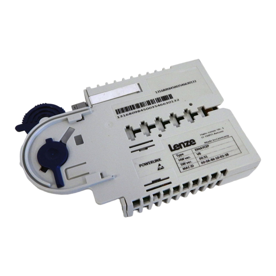
EDK94AYCEP
.G<d
L−force Communication
Ethernet POWERLINK
E94AYCEP
Kommunikationsmodul
Communication module
Module de communication
Módulo de comunicación
Modulo di comunicazione
Montageanleitung
Mounting Instructions
Instructions de montage
Instrucciones para el montaje
Istruzioni per il montaggio
l
Publicité

Manuels Connexes pour Lenze Ethernet POWERLINK E94AYCEP


Sommaire des Matières pour Lenze Ethernet POWERLINK E94AYCEP
- Page 1 All manuals and user guides at all-guides.com EDK94AYCEP L−force Communication .G<d Montageanleitung Mounting Instructions Instructions de montage Instrucciones para el montaje Istruzioni per il montaggio Ethernet POWERLINK E94AYCEP Kommunikationsmodul Communication module Module de communication Módulo de comunicación Modulo di comunicazione...
- Page 2 All manuals and user guides at all-guides.com Lesen Sie zuerst diese Anleitung, bevor Sie mit den Arbeiten beginnen! Beachten Sie die enthaltenen Sicherheitshinweise. Please read these instructions before you start working! Follow the enclosed safety instructions. Veuillez lire attentivement cette documentation avant toute action ! Les consignes de sécurité...
- Page 3 All manuals and user guides at all-guides.com E94YCEP001A E94YCEP017...
- Page 4 All manuals and user guides at all-guides.com Legende zur Abbildung auf der Ausklappseite Pos. Beschreibung Ausführliche Information X210 Anschluss für externe Spannungsversorgung ^ 20 2−polige Steckerleiste mit Schraubanschluss Ethernet POWERLINK−Anschlüsse X211 ^ 17 RJ45−Buchse nach IEC 60603−7 X212 ^ 21 S233 DIP−Schalter zur Adressierung des Teilnehmers ^ 23...
- Page 5 All manuals and user guides at all-guides.com Inhalt Über diese Dokumentation ......... . Verwendete Konventionen .
- Page 6 E94AYCEP 00.50 Zielgruppe Diese Dokumentation richtet sich an Personen, die die Vernetzung und Fernwartung einer Maschine projektieren, installieren, in Betrieb nehmen und warten. Tipp! Informationen und Hilfsmittel rund um die Lenze−Produkte finden Sie im Download−Bereich unter http://www.Lenze.com EDK94AYCEP DE/EN/FR/ES/IT 4.0...
- Page 7 All manuals and user guides at all-guides.com Über diese Dokumentation Verwendete Konventionen Verwendete Konventionen Diese Dokumentation verwendet folgende Konventionen zur Unterscheidung verschiede- ner Arten von Information: Informationsart Auszeichnung Beispiele/Hinweise Zahlenschreibweise Dezimaltrennzeichen Punkt Es wird generell der Dezimalpunkt verwendet. Beispiel: 1234.56 Symbole Seitenverweis Verweis auf eine andere Seite mit zu-...
- Page 8 All manuals and user guides at all-guides.com Über diese Dokumentation Verwendete Hinweise Verwendete Hinweise Um auf Gefahren und wichtige Informationen hinzuweisen, werden in dieser Dokumenta- tion folgende Piktogramme und Signalwörter verwendet: Sicherheitshinweise Aufbau der Sicherheitshinweise: Gefahr! (kennzeichnet die Art und die Schwere der Gefahr) Hinweistext (beschreibt die Gefahr und gibt Hinweise, wie sie vermieden werden kann) Piktogramm und Signalwort...
- Page 9 All manuals and user guides at all-guides.com Über diese Dokumentation Verwendete Hinweise Anwendungshinweise Piktogramm und Signalwort Bedeutung Wichtiger Hinweis für die störungsfreie Funktion Hinweis! Nützlicher Tipp für die einfache Handhabung Tipp! Verweis auf andere Dokumentation EDK94AYCEP DE/EN/FR/ES/IT 4.0...
- Page 10 All manuals and user guides at all-guides.com Sicherheitshinweise Sicherheitshinweise Gefahr! Unsachgemäßer Umgang mit dem Kommunikationsmodul und dem Grundgerät kann schwere Personenschäden und Sachschäden verursachen. Beachten Sie die in der Dokumentation zum Grundgerät enthaltenen Sicherheitshinweise und Restgefahren. Stop! Elektrostatische Entladung Durch elektrostatische Entladung können elektronische Bauteile innerhalb des Kommunikationsmoduls beschädigt oder zerstört werden.
- Page 11 All manuals and user guides at all-guides.com Produktbeschreibung Funktion Produktbeschreibung Funktion Das Kommunikationsmodul koppelt Lenze Servo Drives 9400 an das Kommunikationssys- tem Ethernet POWERLINK. Unterstützte Funktionalitäten: ƒ Managing Node (Unterstützung von bis zu 50 Teilnehmern) ƒ Controlled Node Bestimmungsgemäße Verwendung Das Kommunikationsmodul ...
- Page 12 All manuals and user guides at all-guides.com Produktbeschreibung Identifikation Identifikation E94YCEI003C ‚ ƒ 0.50 Produktreihe Gerätegeneration Modulkennung: Erweiterungsmodul Modultyp: Kommunikationsmodul Ethernet POWERLINK Hardwarestand Softwarestand EDK94AYCEP DE/EN/FR/ES/IT 4.0...
- Page 13 All manuals and user guides at all-guides.com Technische Daten Allgemeine Daten Technische Daten Allgemeine Daten Bereich Werte Bestell−Bezeichnung E94AYCEP Kommunikationsprofil Ethernet POWERLINK V2 Kommunikationsmedium S/FTP (Screened Foiled Twisted Pair, ISO/IEC 11801 oder EN 50173), CAT 5e Schnittstelle für Kommuni- RJ45: Standard Ethernet (nach IEEE 802.3), 100Base−TX (Fast Ethernet) kation Leitungslänge zwischen max.
- Page 14 All manuals and user guides at all-guides.com Technische Daten Abmessungen Abmessungen E94YCXX005 89 mm 134 mm 87 mm 23 mm EDK94AYCEP DE/EN/FR/ES/IT 4.0...
- Page 15 All manuals and user guides at all-guides.com Mechanische Installation Mechanische Installation Montage E94YCXX001G Demontage E94AYCXX001H EDK94AYCEP DE/EN/FR/ES/IT 4.0...
- Page 16 All manuals and user guides at all-guides.com Elektrische Installation EMV−gerechte Verdrahtung Elektrische Installation EMV−gerechte Verdrahtung In typischen Anlagen ist die standardmäßige Schirmung der Ethernet−Kabel ausreichend. In sehr stark gestörten Umgebungen kann eine Verbesserung der EMV−Festigkeit durch eine zusätzliche beidseitige Erdung des Kabelschirms ermöglicht werden. Beachten Sie dazu folgende Hinweise: 1.
- Page 17 All manuals and user guides at all-guides.com Elektrische Installation Ethernet POWERLINK−Anschluss Ethernet POWERLINK−Anschluss Zum Anschluss an das Kommunikationsmodul eignet sich ein handelsübliches Standard− Ethernet−Patchkabel (siehe "Spezifikation des Ethernet−Kabels" (^ 19)). Die Montage und Demontage der Ethernet−Kabel ist optimiert zur Verwendung von Steck- verbindern gemäß...
- Page 18 All manuals and user guides at all-guides.com Elektrische Installation Ethernet POWERLINK−Anschluss Pinbelegung RJ45−Buchse Signal Tx + Tx − Rx + − − Rx− − E94YCEP004C − Tipp! Die Ethernet POWERLINK−Schnittstellen verfügen über eine Auto−MDIX−Funktion. Diese Funktion passt die Polung der RJ45−Schnittstellen so an, dass unabhängig von der Polung der gegenüberliegenden Ethernet POWERLINK−Schnittstelle und dem verwendeten Kabeltyp (Standard−Patch−Kabel oder Cross−Over−Kabel) eine Verbindung hergestellt...
- Page 19 All manuals and user guides at all-guides.com Elektrische Installation Ethernet POWERLINK−Anschluss Spezifikation des Ethernet−Kabels Hinweis! Verwenden Sie ausschließlich Kabel, die den aufgeführten Spezifikationen entsprechen. Spezifikation des Ethernet−Kabels Ethernet−Standard Standard Ethernet (nach IEEE 802.3), 100Base−TX (Fast Ethernet) Kabeltyp S/FTP (Screened Foiled Twisted Pair, ISO/IEC 11801 oder EN 50173), CAT 5e Dämpfung 23.2 dB (bei 100 MHz und je 100 m)
- Page 20 All manuals and user guides at all-guides.com Elektrische Installation Externe Spannungsversorgung Externe Spannungsversorgung Hinweis! Verwenden Sie bei externer Spannungsversorgung und bei größeren Entfernungen zwischen den Schaltschränken in jedem Schaltschrank immer ein separates und nach EN 61800−5−1 sicher getrenntes Netzteil ("SELV"/"PELV"). Die externe Spannungsversorgung des Kommunikationsmoduls ist notwendig, wenn beim Ausfall der Versorgung des Grundgerätes die Ethernet POWERLINK−Kommunikation beste- hen bleiben soll.
- Page 21 1 … 239 E94AYCEP ist Controlled Node mit Managing Node eines anderen Herstel- lers. ƒ Lenze−Einstellung der DIP−Schalter 1 ... 128 = OFF (ungültiger Wert "0") ƒ Die Gehäuse−Beschriftung entspricht den Wertigkeiten der einzelnen DIP−Schalter zur Bestimmung der Stationsadresse. EDK94AYCEP DE/EN/FR/ES/IT 4.0...
- Page 22 All manuals and user guides at all-guides.com Inbetriebnahme Teilnehmeradresse einstellen Beispiel: Einstellung der Teilnehmeradresse 23 DIP−Schalter Schalterzustand Wertigkeit Teilnehmeradresse = Summer der Wertigkeiten = 16 + 4 + 2 + 1 = 23 Hinweis! Schalten Sie die Spannungsversorgung des Kommunikationsmoduls aus und anschließend wieder ein, um geänderte Einstellungen zu aktivieren.
- Page 23 All manuals and user guides at all-guides.com Diagnose LED−Statusanzeigen Diagnose LED−Statusanzeigen Pos. Farbe Zustand Beschreibung grün blinkt Das Kommunikationsmodul ist mit Spannung versorgt, hat aber keine Verbin- dung zum Grundgerät. (Grundgerät ist ausgeschaltet, in der Initialisierungs- phase oder nicht vorhanden.) Das Kommunikationsmodul ist mit Spannung versorgt und hat eine Verbin- dung zum Grundgerät.
- Page 24 All manuals and user guides at all-guides.com Diagnose LED−Statusanzeigen Pos. Farbe Zustand Beschreibung Beschreibung Signalisierung an den RJ45−Buchsen (X211, X212): − Eine Ethernet POWERLINK−Kollision liegt vor. − grün Keine Ethernet POWERLINK−Verbindung Die Ethernet POWERLINK−Verbindung ist vorhanden. blinkt Aktive Datenkommunikation über Ethernet POWERLINK EDK94AYCEP DE/EN/FR/ES/IT 4.0...
- Page 25 All manuals and user guides at all-guides.com Diagnose LED−Statusanzeigen EDK94AYCEP DE/EN/FR/ES/IT 4.0...
- Page 26 All manuals and user guides at all-guides.com Legend for fold−out page Pos. Description Detailed information X210 Connection for external voltage supply ^ 42 2−pole plug connector with screw connection Ethernet POWERLINK connections X211 ^ 39 RJ45 socket according to IEC 60603−7 X212 ^ 43 S233...
- Page 27 All manuals and user guides at all-guides.com Contents About this documentation ......... . . Conventions used .
- Page 28 ƒ information on the mechanical and electrical installation of the communication module; ƒ safety instructions which must be observed by all means; ƒ information about versions of the Lenze standard devices to be used; ƒ Information on the LED status displays. Validity information...
- Page 29 All manuals and user guides at all-guides.com About this documentation Conventions used Conventions used This documentation uses the following conventions to distinguish between different types of information: Type of information Identification Examples/notes Numbers Decimal separator Point The decimal point is used throughout this documentation.
- Page 30 All manuals and user guides at all-guides.com About this documentation Notes used Notes used The following pictographs and signal words are used in this documentation to indicate dangers and important information: Safety instructions Structure of safety instructions: Danger! (characterises the type and severity of danger) Note (describes the danger and gives information about how to prevent dangerous situations)
- Page 31 All manuals and user guides at all-guides.com About this documentation Notes used Application notes Pictograph and signal word Meaning Important note to ensure troublefree operation Note! Useful tip for simple handling Tip! Reference to another documentation EDK94AYCEP DE/EN/FR/ES/IT 4.0...
- Page 32 All manuals and user guides at all-guides.com Safety instructions Safety instructions Danger! Inappropriate handling of the communication module and the standard device can cause serious personal injury and material damage. Observe the safety instructions and residual hazards described in the documentation for the standard device.
- Page 33 ƒ Managing node (support of up to 50 nodes) ƒ Controlled node Application as directed The communication module ... ƒ is an accessory module which can be used in conjunction with the following Lenze standard devices: Product series Type designation...
- Page 34 All manuals and user guides at all-guides.com Product description Identification Identification E94YCEI003C ‚ ƒ 0.50 Product series Device generation Module identification: extension module Module type: communication module Ethernet POWERLINK Hardware version Software version EDK94AYCEP DE/EN/FR/ES/IT 4.0...
- Page 35 All manuals and user guides at all-guides.com Technical data General data Technical data General data Field Values Order designation E94AYCEP Communication profile Ethernet POWERLINK V2 Communication medium S/FTP (Screened Foiled Twisted Pair, ISO/IEC 11801 or EN 50173), CAT Interface for RJ45: Standard Ethernet (according to IEEE 802.3), 100Base−TX (fast communication Ethernet)
- Page 36 All manuals and user guides at all-guides.com Technical data Dimensions Dimensions E94YCXX005 89 mm 134 mm 87 mm 23 mm EDK94AYCEP DE/EN/FR/ES/IT 4.0...
- Page 37 All manuals and user guides at all-guides.com Mechanical installation Mechanical installation Mounting E94YCXX001G Dismounting E94AYCXX001H EDK94AYCEP DE/EN/FR/ES/IT 4.0...
- Page 38 All manuals and user guides at all-guides.com Electrical installation Wiring according to EMC Electrical installation Wiring according to EMC In typical systems, standard shielding of the Ethernet cables is sufficient. In environments with a very high level of interference, immunity to noise can be improved by additionally earthing the cable shield on both sides.
- Page 39 All manuals and user guides at all-guides.com Electrical installation Ethernet POWERLINK connection Ethernet POWERLINK connection You can use a standard Ethernet patch cable for connection to the communication module (see "Ethernet cable specifications" (^ 41)). Mounting and dismounting of the Ethernet cables has been optimised for the use of connectors according to the "Automation Initiative of German Domestic Automobile Manufacturers"...
- Page 40 All manuals and user guides at all-guides.com Electrical installation Ethernet POWERLINK connection Pin assignment RJ45 socket Signal Tx + Tx − Rx + − − Rx − − E94YCEP004C − Tip! The Ethernet POWERLINK interfaces are equipped with an auto−MDIX function. This function adapts the polarity of the RJ45 interfaces such that independently of the polarity of the opposite Ethernet POWERLINK interface and the cable type used (standard patch cable or crossover cable) a connection...
- Page 41 All manuals and user guides at all-guides.com Electrical installation Ethernet POWERLINK connection Ethernet cable specifications Note! Only use cables complying with the below specifications. Specification of the Ethernet cable Ethernet standard Standard Ethernet (in accordance with IEEE 802.3), 100Base−TX (Fast Ethernet) Cable type S/FTP (Screened Foiled Twisted Pair, ISO/IEC 11801 or EN 50173), CAT 5e...
- Page 42 All manuals and user guides at all-guides.com Electrical installation External voltage supply External voltage supply Note! Always use a separate power supply unit in every control cabinet and safely separate it according to EN 61800−5−1 ("SELV"/"PELV") in the case of external voltage supply and larger distances between the control cabinets.
- Page 43 E94AYCEP is a controlled node with a managing node of a different manufacturer. ƒ Lenze setting of the DIP switches 1 ... 128 = OFF (invalid value "0") ƒ The housing labelling corresponds to the valencies of the individual DIP switches for determining the station address.
- Page 44 All manuals and user guides at all-guides.com Commissioning Setting the node address Example: Setting of the node address 23 DIP switch Switch status Valency Node address = sum of valencies = 16 + 4 + 2 + 1 = 23 Note! Switch off and then on again the voltage supply of the communication module to activate changed settings.
- Page 45 All manuals and user guides at all-guides.com Diagnostics LED status displays Diagnostics LED status displays Pos. Colour Condition Description Green Blinking The communication module is supplied with voltage, but has no connection to the basic device (basic device is either switched off, in the initialisation phase, or not available).
- Page 46 All manuals and user guides at all-guides.com Diagnostics LED status displays Pos. Colour Condition Description Description Signalling at the RJ45 sockets (X211, X212): − An Ethernet POWERLINK collision is available. − Green No Ethernet POWERLINK connection Ethernet POWERLINK connection is available. Blinking Active data communication via Ethernet POWERLINK EDK94AYCEP DE/EN/FR/ES/IT 4.0...
- Page 47 All manuals and user guides at all-guides.com Diagnostics LED status displays EDK94AYCEP DE/EN/FR/ES/IT 4.0...
- Page 48 All manuals and user guides at all-guides.com Légende de l’illustration de la page dépliante Pos. Description Informations détaillées X210 Raccordement pour alimentation externe ^ 64 Bornier à vis à 2 bornes Raccordements Ethernet POWERLINK X211 ^ 61 Prise RJ45 selon CEI 60603−7 X212 ^ 65 S233...
- Page 49 All manuals and user guides at all-guides.com Sommaire Présentation du document ......... . . Conventions utilisées .
- Page 50 ƒ des informations sur l’installation mécanique et électrique du module de communication ; ƒ des consignes de sécurité qui doivent impérativement être respectées ; ƒ des indications sur les versions des appareils de base Lenze à utiliser ; ƒ des informations sur les affichages d’état par LED. Validité...
- Page 51 All manuals and user guides at all-guides.com Présentation du document Conventions utilisées Conventions utilisées Pour faire la distinction entre différents types d’informations, ce document utilise les conventions suivantes : Type d’information Marquage Exemples/remarques Représentation des chiffres Séparateur décimal Point Le point décimal est généralement utilisé.
- Page 52 All manuals and user guides at all-guides.com Présentation du document Consignes utilisées Consignes utilisées Pour indiquer des risques et des informations importantes, la présente documentation utilise les mots et symboles suivants : Consignes de sécurité Présentation des consignes de sécurité Danger ! (Le pictogramme indique le type de risque.) Explication...
- Page 53 All manuals and user guides at all-guides.com Présentation du document Consignes utilisées Consignes d’utilisation Pictogramme et mot associé Explication Remarque Remarque importante pour assurer un fonctionnement correct importante ! Conseil utile pour faciliter la mise en œuvre Conseil ! Référence à une autre documentation EDK94AYCEP DE/EN/FR/ES/IT 4.0...
- Page 54 All manuals and user guides at all-guides.com Consignes de sécurité Consignes de sécurité Danger ! Toute utilisation non conforme à la fonction du module de communication et de l’appareil de base risque d’entraîner des blessures graves et des dommages matériels. Tenir compte des consignes de sécurité...
- Page 55 Description du produit Fonction Description du produit Fonction Le module de communication relie les appareils Servo Drives 9400 de Lenze au système de communication Ethernet POWERLINK. Fonctionnalités prises en charge : ƒ Managing Node (prise en charge de 50 participants max.) ƒ...
- Page 56 All manuals and user guides at all-guides.com Description du produit Identification Identification E94YCEI003C ‚ ƒ 0.50 Série d’appareils Génération d’appareils Identification du module : module d’extension Type de module : module de communication Ethernet POWERLINK Version matérielle Version logicielle EDK94AYCEP DE/EN/FR/ES/IT 4.0...
- Page 57 All manuals and user guides at all-guides.com Spécifications techniques Caractéristiques générales Spécifications techniques Caractéristiques générales Domaine Valeurs Référence de commande E94AYCEP Profil de communication Ethernet POWERLINK V2 Support de communication S/FTP (Screened Foiled Twisted Pair, ISO/CEI 11801 ou EN 50173), CAT Interface pour la RJ45 : Standard Ethernet (selon IEEE 802.3), 100Base−TX (Fast Ethernet) communication...
- Page 58 All manuals and user guides at all-guides.com Spécifications techniques Encombrements Encombrements E94YCXX005 89 mm 134 mm 87 mm 23 mm EDK94AYCEP DE/EN/FR/ES/IT 4.0...
- Page 59 All manuals and user guides at all-guides.com Installation mécanique Installation mécanique Montage E94YCXX001G Démontage E94AYCXX001H EDK94AYCEP DE/EN/FR/ES/IT 4.0...
- Page 60 All manuals and user guides at all-guides.com Installation électrique Câblage conforme CEM Installation électrique Câblage conforme CEM Dans les installations types, un blindage standard du câble Ethernet suffit. Dans les environnements soumis à de fortes perturbations, il est possible d’améliorer la résistance CEM par une mise à...
- Page 61 All manuals and user guides at all-guides.com Installation électrique Raccordement Ethernet POWERLINK Raccordement Ethernet POWERLINK Le module de communication peut être raccordé à l’aide d’un câble droit Ethernet standard en vente dans le commerce (voir "Spécifications du câble Ethernet" (^ 63)). Le montage et le démontage des câbles Ethernet sont optimisés grâce à...
- Page 62 All manuals and user guides at all-guides.com Installation électrique Raccordement Ethernet POWERLINK Affectation des broches Prise RJ45 Broc Signal Tx + Tx − Rx + − − Rx − − E94YCEP004C − Conseil ! Les interfaces Ethernet POWERLINK sont dotées d’une fonction Auto−MDIX. Celle−ci permet d’adapter l’affectation des broches des prises RJ45 de manière à...
- Page 63 All manuals and user guides at all-guides.com Installation électrique Raccordement Ethernet POWERLINK Spécifications du câble Ethernet Remarque importante ! Utiliser exclusivement des câbles conformes aux spécifications indiquées. Spécifications du câble Ethernet Standard Ethernet Standard Ethernet (selon IEEE 802.3), 100Base−TX (Fast Ethernet) Type de câble S/FTP (Screened Foiled Twisted Pair, ISO/CEI 11801 ou EN 50173), CAT 5e...
- Page 64 All manuals and user guides at all-guides.com Installation électrique Alimentation externe Alimentation externe Remarque importante ! En cas d’alimentation externe et d’écarts importants entre les armoires électriques, utiliser impérativement dans chacune d’elles un bloc d’alimentation avec coupure de sécurité ("SELV"/"PELV") séparé et conforme à la norme EN 61800−5−1.
- Page 65 E94AYCEP est un Controlled Node, avec le Managing Node d’un autre fabricant. ƒ Réglage Lenze des interrupteurs DIP 1 ... 128 = OFF (valeur non valable "0") ƒ Les inscriptions sur le boîtier correspondent aux valeurs des différents interrupteurs DIP déterminant l’adresse du participant.
- Page 66 All manuals and user guides at all-guides.com Mise en service Réglage de l’adresse des participants Exemple : réglage de l’adresse du participant 23 Interrupteur DIP Position de l’interrupteur Valeur Adresse du = somme des valeurs = 16 + 4 + 2 + 1 = 23 participant Remarque importante ! Pour activer un réglage modifié, couper brièvement l’alimentation du module...
- Page 67 All manuals and user guides at all-guides.com Diagnostic Affichages d’état par LED Diagnostic Affichages d’état par LED Pos. Couleur Etat Description Vert Clignote Le module de communication est sous tension, mais la liaison avec l’appareil de base n’est pas établie (l’appareil de base est hors tension, en cours d’initialisation ou aucun appareil de base n’est présent).
- Page 68 All manuals and user guides at all-guides.com Diagnostic Affichages d’état par LED Pos. Couleur Etat Description Description Signalisation au niveau des prises RJ45 (X211, X212) : − Rouge Collision Ethernet POWERLINK − Vert Pas de liaison Ethernet POWERLINK La liaison avec le réseau Ethernet POWERLINK est établie. Clignote Communication de données via Ethernet POWERLINK en cours EDK94AYCEP DE/EN/FR/ES/IT 4.0...
- Page 69 All manuals and user guides at all-guides.com Diagnostic Affichages d’état par LED EDK94AYCEP DE/EN/FR/ES/IT 4.0...
- Page 70 All manuals and user guides at all-guides.com Leyenda de la ilustración del lado abatible Pos. Descripción Información detallada X210 Conexión para la alimentación de voltaje externa ^ 85 Regleta de conectores de 2 polos con conexión atornillada Conexiones Ethernet POWERLINK X211 ^ 82 Conector hembra RJ45 según IEC 60603−7...
- Page 71 All manuals and user guides at all-guides.com Contenido Acerca de esta documentación ........Convenciones utilizadas .
- Page 72 ƒ Información para la instalación mecánica y eléctrica del módulo de comunicaciones. ƒ Instrucciones de Seguridad que deben ser aplicadas. ƒ Datos de las versiones de los equipos básicos Lenze que deben ser utilizados. ƒ Información sobre la indicación del estado mediante LEDs.
- Page 73 All manuals and user guides at all-guides.com Acerca de esta documentación Convenciones utilizadas Convenciones utilizadas Esta documentación utiliza las siguientes convenciones para distinguir diferentes tipos de información: Tipo de información Marcación Ejemplos/indicaciones Números Separador decimal Punto En general se usa el punto decimal. Ejemplo: 1234.56 Símbolos Referencia de página...
- Page 74 All manuals and user guides at all-guides.com Acerca de esta documentación Indicaciones utilizadas Indicaciones utilizadas Para indicar peligros e información importante, se utilizan en esta documentación los siguientes términos indicativos y símbolos: Instrucciones de seguridad Estructura de las instrucciones de seguridad: ¡Peligro! (indican el tipo y la gravedad del peligro) Texto indicativo...
- Page 75 All manuals and user guides at all-guides.com Instrucciones de seguridad Instrucciones de seguridad ¡Peligro! El uso inapropiado del módulo de comunicaciones y del equipo básico puede causar accidentes y daños materiales. Observe las Instrucciones de Seguridad y Riesgos Residuales contenidos en la documentación del equipo básico.
- Page 76 All manuals and user guides at all-guides.com Descripción del producto Función Descripción del producto Función El módulo de comunicaciones acopla al Lenze Servo Drives 9400 al sistema de comunicaciones Ethernet POWERLINK. Funcionalidades soportadas: ƒ Managing Node (soporte de hasta 50 dispositivos) ƒ Controlled Node Uso previsto El módulo de comunicaciones...
- Page 77 All manuals and user guides at all-guides.com Descripción del producto Identificación Identificación E94YCEI003C ‚ ƒ 0.50 Serie de productos Versión de equipos Caracterización del módulo: Módulo de extensión Tipo de módulo: Módulo de comunicaciones Ethernet POWERLINK Versión de hardware Versión de software EDK94AYCEP DE/EN/FR/ES/IT 4.0...
- Page 78 All manuals and user guides at all-guides.com Datos técnicos Datos generales Datos técnicos Datos generales Ámbito Valores Ref. para pedidos E94AYCEP Perfil de comunicaciones Ethernet POWERLINK V2 Medio de comunicación S/FTP (Screened Foiled Twisted Pair, ISO/IEC 11801 o EN 50173), CAT 5e Interface para la RJ45: Ethernet estándar (según IEEE 802.3), 100Base−TX (Fast Ethernet) comunicación...
- Page 79 All manuals and user guides at all-guides.com Datos técnicos Dimensiones Dimensiones E94YCXX005 89 mm 134 mm 87 mm 23 mm EDK94AYCEP DE/EN/FR/ES/IT 4.0...
- Page 80 All manuals and user guides at all-guides.com Instalación mecánica Instalación mecánica Montaje E94YCXX001G Desmontaje E94AYCXX001H EDK94AYCEP DE/EN/FR/ES/IT 4.0...
- Page 81 All manuals and user guides at all-guides.com Instalación eléctrica Cableado según CEM Instalación eléctrica Cableado según CEM En instalaciones típicas es suficiente el apantallado estándar de los cables Ethernet. En instalaciones con fuertes interferencias se puede mejorar la resistencia CEM mediante una puesta a tierra adicional de la malla del cable a ambos lados.
- Page 82 All manuals and user guides at all-guides.com Instalación eléctrica Conexión a Ethernet POWERLINK Conexión a Ethernet POWERLINK Para la conexión con el módulo de comunicaciones es adecuado el uso del cable patch Ethernet estándar disponible en los comercios (véase «Especificación del cable Ethernet» (^ 84)).
- Page 83 All manuals and user guides at all-guides.com Instalación eléctrica Conexión a Ethernet POWERLINK Asignación de pins Conector RJ45 Señal Tx + Tx − Rx + − − Rx − − E94YCEP004C − ¡Sugerencia! Los interfaces de Ethernet POWERLINK disponen de una función Auto−MDIX. Esta función adapta la polaridad de los interfaces RJ45 de tal manera que se establece una conexión independientemente de la polaridad del interface Ethernet POWERLINK y del tipo de cable utilizado (cable patch estándar o cable...
- Page 84 All manuals and user guides at all-guides.com Instalación eléctrica Conexión a Ethernet POWERLINK Especificación del cable Ethernet ¡Aviso! Sólo utilice cables conforme a las especificaciones indicadas. Especificaciones del cable Ethernet Ethernet estándar Ethernet estándar (según IEEE 802.3), 100Base−TX (Fast Ethernet) Tipo de cable S/FTP (Screened Foiled Twisted Pair, ISO/IEC 11801 o EN 50173), CAT 5e...
- Page 85 All manuals and user guides at all-guides.com Instalación eléctrica Voltaje de alimentación externo Voltaje de alimentación externo ¡Aviso! En caso de que exista un voltaje de alimentación externo y que haya una gran distancia entre los armarios de distribución, utilice en cada armario de distribución una fuente de alimentación independiente y con separación segura conforme a EN 61800−5−1 («SELV»/«PELV»).
- Page 86 E94AYCEP es el Controlled Node con Managing Node de otro fabricante. ƒ Configuración Lenze de los interruptores DIP 1 ... 128 = OFF (valor no válido "0") ƒ La rotulación de la carcasa corresponde a las valencias de los distintos interruptores DIP para determinar la dirección de la estación.
- Page 87 All manuals and user guides at all-guides.com Puesta en marcha Configurar la dirección del dispositivo Ejemplo: Configuración de la dirección de dispositivo 23 Interruptor DIP Estado del interruptor Valencia Dirección de = suma de todas las valencias = 16 + 4 + 2 + 1 = 23 dispositivo ¡Aviso! Desconecte la alimentación de voltaje del módulo de comunicaciones y vuelva...
- Page 88 All manuals and user guides at all-guides.com Diagnóstico Indicadores de estado LED Diagnóstico Indicadores de estado LED Pos. Color Estado Descripción verde parpadea El módulo de comunicaciones está siendo alimentado pero no tiene comunicación con el equipo básico. (El equipo básico está desconectado, está en fase de inicialización o no está...
- Page 89 All manuals and user guides at all-guides.com Diagnóstico Indicadores de estado LED Pos. Color Estado Descripción Descripción Señalización en los conectores hembra RJ45 (X211, X212): − rojo encendido Existe una colisión de Ethernet POWERLINK. − verde apagado No existe una conexión con Ethernet POWERLINK. encendido Existe conexión con Ethernet POWERLINK.
- Page 90 All manuals and user guides at all-guides.com Legenda figura su pagina ripiegata Pos. Descrizione Informazioni dettagliate X210 Collegamento per alimentazione esterna ^ 105 Morsettiera a 2 poli con collegamento a vite Collegamenti Ethernet POWERLINK X211 ^ 102 Connettore femmina RJ45 secondo IEC 60603−7 X212 ^ 106 S233...
- Page 91 All manuals and user guides at all-guides.com Sommario Informazioni sul manuale ..........Convenzioni utilizzate .
- Page 92 La presente documentazione è rivolta al personale responsabile della progettazione, installazione, messa in servizio e manutenzione dei collegamenti di rete e del telecontrollo di una macchina. Suggerimento: Per informazioni e altri documenti utili sui prodotti Lenze consultate l’area download del sito http://www.Lenze.com EDK94AYCEP DE/EN/FR/ES/IT 4.0...
- Page 93 All manuals and user guides at all-guides.com Informazioni sul manuale Convenzioni utilizzate Convenzioni utilizzate La presente documentazione utilizza le seguenti convenzioni tipografiche per distinguere i diversi tipi di informazioni: Tipo di informazione Convenzione Esempi/Note tipografica Modalità di scrittura dei numeri Separatore decimale Punto Generalmente si utilizza il punto...
- Page 94 All manuals and user guides at all-guides.com Informazioni sul manuale Avvertenze utilizzate Avvertenze utilizzate Per segnalare pericoli ed informazioni importanti, nella presente documentazione sono riportati i seguenti simboli e parole di segnalazione: Note di sicurezza Struttura delle note di sicurezza: Pericolo! (indica il tipo e la gravità...
- Page 95 All manuals and user guides at all-guides.com Informazioni sulla sicurezza Informazioni sulla sicurezza Pericolo! Un utilizzo improprio del modulo di comunicazione e del dispositivo base può causare gravi danni materiali e alle persone. Rispettare le informazioni sulla sicurezza e sugli altri pericoli contenute nella documentazione relativa al dispositivo base.
- Page 96 All manuals and user guides at all-guides.com Descrizione del prodotto Funzione Descrizione del prodotto Funzione Il modulo di comunicazione collega i Servo Drives 9400 Lenze al sistema di comunicazione Ethernet POWERLINK. Funzionalità supportate: ƒ Managing Node (sono supportati fino a 50 nodi) ƒ Controlled Node Utilizzo conforme Il modulo di comunicazione ...
- Page 97 All manuals and user guides at all-guides.com Descrizione del prodotto Identificazione Identificazione E94YCEI003C ‚ ƒ 0.50 Serie Versione Identificazione modulo: modulo di espansione Tipo di modulo: modulo di comunicazione Ethernet POWERLINK Versione hardware Versione software EDK94AYCEP DE/EN/FR/ES/IT 4.0...
- Page 98 All manuals and user guides at all-guides.com Dati tecnici Dati generali Dati tecnici Dati generali Campo Valori Codice per l’ordine E94AYCEP Profilo di comunicazione Ethernet POWERLINK V2 Mezzo di comunicazione S/FTP (Screened Foiled Twisted Pair, ISO/IEC 11801 o EN 50173), CAT 5e Interfaccia di RJ45: Standard Ethernet (secondo IEEE 802.3), 100Base−TX (Fast comunicazione...
- Page 99 All manuals and user guides at all-guides.com Dati tecnici Dimensioni Dimensioni E94YCXX005 89 mm 134 mm 87 mm 23 mm EDK94AYCEP DE/EN/FR/ES/IT 4.0...
- Page 100 All manuals and user guides at all-guides.com Installazione meccanica Installazione meccanica Montaggio E94YCXX001G Smontaggio E94AYCXX001H EDK94AYCEP DE/EN/FR/ES/IT 4.0...
- Page 101 All manuals and user guides at all-guides.com Installazione elettrica Cablaggio a norma EMC Installazione elettrica Cablaggio a norma EMC Nei normali impianti è sufficiente una schermatura standard del cavo Ethernet. In ambienti con forti interferenze, per migliorare l’immunità EMC è possibile realizzare un ulteriore collegamento a terra su entrambi i lati della schermatura del cavo.
- Page 102 All manuals and user guides at all-guides.com Installazione elettrica Collegamento Ethernet POWERLINK Collegamento Ethernet POWERLINK Per il collegamento con il modulo di comunicazione è possibile utilizzare un cavo patch Ethernet standard, reperibile in commercio (vedere "Specifiche del cavo Ethernet" (^ 104)). Il montaggio e lo smontaggio dei cavi Ethernet è...
- Page 103 All manuals and user guides at all-guides.com Installazione elettrica Collegamento Ethernet POWERLINK Assegnazione dei pin Connettore femmina RJ45 Segnale Tx + Tx − Rx + − − Rx − − E94YCEP004C − Suggerimento: Le interfacce Ethernet POWERLINK sono dotate di una funzione Auto−MDIX. Questa funzione adatta la polarità...
- Page 104 All manuals and user guides at all-guides.com Installazione elettrica Collegamento Ethernet POWERLINK Specifiche del cavo Ethernet Avvertenza: Utilizzare esclusivamente cavi conformi alle specifiche. Specifiche del cavo Ethernet Standard Ethernet Ethernet standard (secondo IEEE 802.3), 100Base−TX (Fast Ethernet) Tipo di cavo S/FTP (Screened Foiled Twisted Pair, ISO/IEC 11801 o EN 50173), CAT 5e Attenuazione...
- Page 105 All manuals and user guides at all-guides.com Installazione elettrica Alimentazione esterna Alimentazione esterna Avvertenza: In caso di alimentazione esterna e di distanze elevate tra gli armadi elettrici, utilizzare sempre in ciascun armadio elettrico un alimentatore separato e con isolamento sicuro secondo la norma EN 61800−5−1 ("SELV/PELV"). L’alimentazione esterna del modulo di comunicazione è...
- Page 106 E94AYCEP è un Controlled Node con Managing Node di un altro produttore. ƒ Impostazione Lenze dei DIP switch 1 ... 128 = OFF (valore non valido "0") ƒ I numeri riportati sul modulo corrispondono alle valenze dei singoli DIP switch per la determinazione dell’indirizzo di stazione.
- Page 107 All manuals and user guides at all-guides.com Messa in servizio Impostazione dell’indirizzo di nodo Esempio: impostazione dell’indirizzo di nodo 23 DIP switch Stato switch Valenza Indirizzo di nodo = Somma delle valenze = 16 + 4 + 2 + 1 = 23 Avvertenza: Per attivare le impostazioni modificate, spegnere e riaccendere il modulo di comunicazione.
- Page 108 All manuals and user guides at all-guides.com Diagnostica Indicatori di stato a LED Diagnostica Indicatori di stato a LED Pos. Colore Stato Descrizione verde lampeggiante Il modulo di comunicazione riceve la tensione di alimentazione, ma non è stata rilevata alcuna connessione con il dispositivo base (questo è spento, in fase di inizializzazione o non presente).
- Page 109 All manuals and user guides at all-guides.com Diagnostica Indicatori di stato a LED Pos. Colore Stato Descrizione Descrizione Segnalazioni alle prese RJ45 (X211, X212): − rosso acceso Si è verificata una collisione Ethernet POWERLINK. − verde spento Nessuna connessione Ethernet POWERLINK. acceso La connessione Ethernet POWERLINK è...
- Page 110 All manuals and user guides at all-guides.com Lenze Automation GmbH EDK94AYCEP Hans−Lenze−Str. 1 DE/EN/FR/ES/IT 4.0 D−31855 Aerzen © 06/2011 Germany TD17 +49 (0)51 54 / 82−0 Service 00 80 00 / 24 4 68 77 (24 h helpline) Ê Service +49 (0)51 54 / 82 −...