Publicité
Les langues disponibles
Les langues disponibles
Liens rapides
CM5_WithAnybus_QM_9752090130_NL_D_GB_F_IT_V2_0
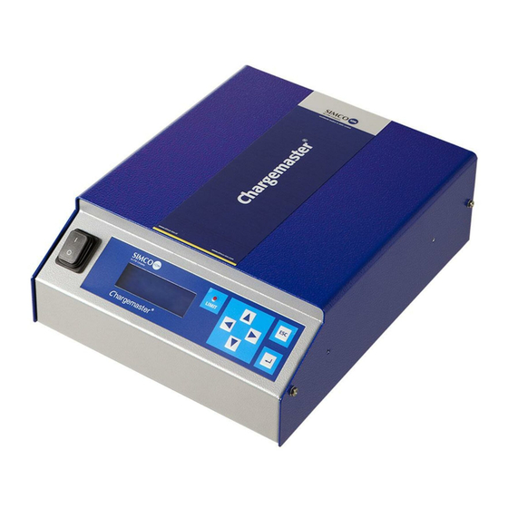
Quick manual
Het gebruik van de CM5 met Profibus module
Die Verwendung des CM5 mit Profibus-Modul
Using the CM5 with Profibus module
Utilisation du CM5 avec le module Profibus
Uso del CM5 con modulo Profibus
NL
Quick manual
D
Kurzanleitung
GB
Quick manual
F
Manuel d'installation rapide
IT
Manuale rapido
CM5
SIMCO (Nederland) B.V.
Postbus 71
NL-7240 AB Lochem
Telefoon + 31-(0)573-288333
Telefax
+ 31-(0)573-257319
E-mail
general@simco-ion.nl
Internet
http://www.simco-ion.nl
Traderegister Apeldoorn No. 08046136
1
7
14
20
27
Publicité
Chapitres

Sommaire des Matières pour ITW Simco-Ion CM5
- Page 1 SIMCO (Nederland) B.V. Postbus 71 NL-7240 AB Lochem Telefoon + 31-(0)573-288333 Telefax + 31-(0)573-257319 E-mail general@simco-ion.nl Internet http://www.simco-ion.nl Traderegister Apeldoorn No. 08046136 Quick manual Het gebruik van de CM5 met Profibus module Die Verwendung des CM5 mit Profibus-Modul Using the CM5 with Profibus module Utilisation du CM5 avec le module Profibus Uso del CM5 con modulo Profibus Quick manual...
-
Page 2: Table Des Matières
INHOUDSOPGAVE Verklaring gebruikte symbolen ....................2 Inleiding ..........................2 Beschrijving en werking ......................2 Technische specificaties ....................... 3 Ingebruikneming ........................3 Controle op de werking ......................6 CM5_WithAnybus_QM_9752090130_NL_D_GB_F_IT_V2_0... -
Page 3: Verklaring Gebruikte Symbolen
1. Verklaring gebruikte symbolen Waarschuwing Verwijst naar speciale informatie ter voorkoming van letsel of aanzienlijke schade aan het product. Let op Belangrijke informatie over efficiënt gebruik en/of ter voorkoming van schade aan het product. 2. Inleiding Deze handleiding is bedoeld als een snelle installatiegids voor gebruik van de CM5 oplaadgenerator met Profibus module, overeenkomstig de ECM DI generator. -
Page 4: Technische Specificaties
4. Technische specificaties Benodigde voeding: Voedingsspanning 100 – 240 V AC Frequentie 50 – 60 Hz Opgenomen vermogen Max. 240 W Omgeving: Gebruik Industrieel, binnengebruik Temperatuur 0 – 55°C Installatie Stof- en trillingsvrij Beschermingsklasse IP20 5. Ingebruikneming Waarschuwing: Elektrische installatie moet gebeuren door een elektrotechnisch vakbekwaam persoon en volgens de nationaal en plaatselijk geldende voorschriften. - Page 5 Sluit de elektroden / oplaadstaven aan op de HV uitgangsconnector (zie uitgebreide handleiding hoofdstuk 5 en 5.5). In / uitschakelen van de netspanning Inschakelen = Zet de schakelaar in positie [ l ]. Uitschakelen = Zet de schakelaar in positie [ 0 ]. Bij het inschakelen van de generator, zal de limit indicatie gedurende 2 seconden knipperen.
- Page 6 uit te schakelen (“Bus”) of om via de externe hardware-ingang de uitgangsspanning te ] om de keuze te bevestigen schakelen (“External”). Druk vervolgens op [ De CM5 is nu geconfigureerd en kan gebruikt worden. Vervolgens zal het hoofdscherm van de CM5 getoond worden.
-
Page 7: Controle Op De Werking
Wijzigen van het Voltage Setpoint Let op: Een onnodig hoge uitgangsspanning moet voorkomen worden omdat anders vonkoverslag kan optreden bij de oplaadstaven of elektroden. Dit zal de werking en de betrouwbaarheid van de oplading schaden. De generator zal standaard in fieldbus mode werkzaam zijn zodat de hoogspanning niet via de toetsen van de generator gewijzigd kan worden. - Page 8 INHALT Erklärung der Symbole ......................8 Einleitung ..........................8 Beschreibung und Betrieb ..................... 8 Technische Daten ......................... 9 Inbetriebnahme ........................9 Funktionsprüfung ........................ 13 CM5_WithAnybus_QM_9752090130_NL_D_GB_F_IT_V2_0...
-
Page 9: Erklärung Der Symbole
1. Erklärung der Symbole Warnung Weist auf besondere Informationen zur Vermeidung von Verletzungen oder schweren Schäden am Produkt hin. Achtung Wichtige Informationen für die effizienteste Nutzung des Produkts und/oder zur Vermeidung von Schäden am Produkt. 2. Einleitung Diese Anleitung ist eine Kurzinstallationsanleitung für die Verwendung des Hochspannungsgenerators CM5 mit Profibus-Modul, der auf den ECM DI abgestimmt ist. -
Page 10: Technische Daten
4. Technische Daten Erforderliche Stromversorgung: Versorgungsspannung 100 – 240 V AC Frequenz 50 – 60 Hz Leistungsaufnahme Max. 240 W Aufstellungsort: Nutzung Industrieller Bereich, in Innenräumen Temperatur 0 – 55°C Installation Staub- und vibrationsfrei Schutzklasse IP20 5. Inbetriebnahme Warnung: Die Elektroinstallation muss von einem qualifizierten Elektrotechniker unter Einhaltung der im jeweiligen Land/der jeweiligen Region geltenden Bestimmungen durchgeführt werden. - Page 11 Hinweis: Die Erdung muss über das Netzkabel und über das externe Erdungskabel zum Erdungspunkt am Generator erfolgen. Verbinden Sie das externe Erdungskabel mit einem geerdeten Teil der Maschine. Schließen Sie die Elektroden/Ladestäbe an den Stecker am Hochspannungsausgang an (weitere Informationen finden Sie in dem vollständigen Handbuch, Abschnitte 5 und 5.5). Ein-/Ausschalten der Netzspannung Einschalten = Stellen Sie den Schalter in die Position [ l ].
- Page 12 bestätigen . Der CM5 wird von nun an in der ausgewählten Sprache bedient. Anschließend wird der folgende Text angezeigt: „Bus address: 126“ (Bus-Adresse: 126) Blättern Sie mit den Tasten [ ] / [ ] durch die Auswahl, bis die gewünschte Bus-Adresse ...
- Page 13 Tastenfunktionen Die Tasten auf dem CM5 sind wie folgt definiert: Anzeigen der Sollwerte, Menüsteuerung, Parameteränderungen Anzeigen der Sollwerte, Menüsteuerung, Parameteränderungen [◄] Anzeigen der Sollwerte, Parameteränderungen [►] Anzeigen der Sollwerte, Parameteränderungen ] Zugriff auf das Menü und die Menüelemente, Menüsteuerung [ESC] Verlassen des Menüs und der Menüelemente Anzeigen des aktuellen Spannungssollwerts Drücken Sie die Taste [◄] oder [►].
-
Page 14: Funktionsprüfung
6. Funktionsprüfung Nach dem Einschalten des Generators blinkt die Lampe der Begrenzungsanzeige 1 bis 2 Sekunden lang. Danach wird die Hintergrundbeleuchtung des Displays allmählich heller, und die folgenden Informationen werden für kurze Zeit angezeigt: Generatortyp, Firmware-Version, die festgelegte Bus-Adresse und ggf. auch andere wesentliche Informationen. Während des normalen Betriebs zeigt der Generator die aktuell gemessenen Werte von Spannung und Strom sowie den Betriebsmodus an. - Page 15 CONTENTS Explanation of symbols ....................... 15 Introduction ......................... 15 Description and operation ....................15 Technical specifications ...................... 16 Commissioning ........................16 Functional check ......................... 19 CM5_WithAnybus_QM_9752090130_NL_D_GB_F_IT_V2_0...
-
Page 16: Explanation Of Symbols
1. Explanation of symbols Warning Indicates special information to prevent injury or significant damage to the product. Attention Important information for making the most efficient use of the product and/or for preventing damage to the product. 2. Introduction This manual serves as a quick installation guide for using the CM5 charging generator with Profibus module, corresponding to the ECM DI. -
Page 17: Technical Specifications
4. Technical specifications Required power supply: Supply voltage 100 – 240 V AC Frequency 50 – 60 Hz Current power Max. 240 W Environment: Industrial, internal use Temperature 0 – 55°C Installation Dust-free and vibration-free Protection class IP20 5. Commissioning Warning: Electrical installation must be carried out by a skilled electrical engineer according to the applicable national and local regulations. - Page 18 Switching the mains voltage on/off - Switching on = Switch to position [ l ]. - Switching off = Switch to position [ 0 ]. When switching on the generator, the limit indicator will flash for 2 seconds. After 2 seconds the background lighting on the display will slowly illuminate and information will be shown about the generator.
- Page 19 Connecting the external high voltage on/off control signal In order to switch the high voltage of the generator on/off via an external control refer to section 5.7 in the full manual. The main screen The LCD display provides information about the status of the generator. This information is shown via texts and symbols.
-
Page 20: Functional Check
The generator operates by default in Fieldbus mode, meaning the high voltage cannot be changed using the keys on the generator. It is only possible to change the high voltage via control of the target system. Raise the output voltage via the target system until the correct result is achieved. Then set the output voltage approx. - Page 21 SOMMAIRE Explication des symboles ....................21 Introduction ......................... 21 Description et fonctionnement..................... 21 Spécifications techniques ....................22 Mise en service ........................22 Vérification du fonctionnement .................... 26 CM5_WithAnybus_QM_9752090130_NL_D_GB_F_IT_V2_0...
-
Page 22: Explication Des Symboles
1. Explication des symboles Avertissement Signale des informations particulières visant à empêcher toute blessure ou dommage important au produit. Attention Signale des informations importantes pour assurer l'utilisation la plus efficace du produit et/ou à prévenir tout dommage au produit. 2. Introduction Ce manuel est un guide d'installation rapide du générateur de charge CM5 avec le module Profibus, qui correspond au système ECM DI. -
Page 23: Spécifications Techniques
4. Spécifications techniques Alimentation électrique requise: Tension d’alimentation 100 – 240 V AC Fréquence 50 – 60 Hz Intensité Max. 240 W Environnement: Utilisation Utilisation industrielle, interne Température 0 – 55°C Installation Sans poussière ni vibration Classe de protection IP20 5. - Page 24 Observation: La mise à la terre doit s'effectuer via le câble d'alimentation et le câble de mise à la terre externe branché sur le point de terre du générateur. Branchez le câble de mise à la terre externe à une pièce mise à la terre de la machine. Connectez les électrodes/barres de chargement au connecteur de sortie haute tension (voir sections 5 et 5.5 du manuel intégral).
- Page 25 Servez-vous des touches [ ] / [ ] pour effectuer vos sélections jusqu'à ce que l'adresse du bus ] pour confirmer le choix désiré [1…125] clignote à l'écran. Appuyez ensuite sur [ « Fieldbus source: Bus » (Source bus de terrain : Bus) Servez-vous des touches [ ] / [ ] pour effectuer vos sélections jusqu'à...
- Page 26 Fonctions des touches Les touches du CM5 sont définies comme suit : Permet d'afficher les valeurs du point de consigne. Commande du menu, modification des paramètres. Permet d'afficher les valeurs du point de consigne. Commande du menu, modification des paramètres. [◄] Permet d'afficher les valeurs du point de consigne.
-
Page 27: Vérification Du Fonctionnement
6. Vérification du fonctionnement Après la mise sous tension du générateur, l'indicateur de limite clignote pendant 1 à 2 secondes. Le rétro-éclairage de l'écran s'éclaire doucement et les informations suivantes s'affichent brièvement : le type de générateur, la version du micrologiciel, l'adresse définie du bus et, dans certains cas, d'autres informations adéquates. - Page 28 INDICE Descrizione dei simboli ....................... 28 Introduzione ........................28 Descrizione e funzionamento ....................28 Specifiche tecniche ......................29 Messa in funzione ....................... 29 Controllo funzionale ......................33 CM5_WithAnybus_QM_9752090130_NL_D_GB_F_IT_V2_0...
-
Page 29: Descrizione Dei Simboli
1. Descrizione dei simboli Avvertenza Fornisce informazioni speciali per prevenire lesioni alle persone o danni significativi al prodotto. Attenzione Informazioni importanti per un uso efficiente del prodotto e/o per prevenire danni all'apparecchiatura. 2. Introduzione Questo manuale è inteso come una guida rapida di installazione per l'uso del generatore di carica CM5 con modulo Profibus, conformemente al generatore ECM DI. -
Page 30: Specifiche Tecniche
4. Specifiche tecniche Alimentazione richiesta: Tensione di alimentazione 100 – 240 V AC Frequenza 50 – 60 Hz Corrente di alimentazione Max. 240 W Ambiente: Industriale, uso interno Temperatura 0 – 55°C Installazione In assenza di polvere e vibrazioni Classe di protezione IP20 5. - Page 31 Collegare gli elettrodi / le barre di carico al connettore di uscita HV (vedere il manuale esteso, capitoli 5 e 5.5). Attivazione/disattivazione tensione della rete elettrica Attivazione = Posizione [ l ]. Disattivazione = Posizione [ 0 ]. Quando si accende il generatore, l'indicatore di limite lampeggia per 2 secondi. Dopo 2 secondi la retroilluminazione del display si accende lentamente e mostra le informazioni relative al generatore.
- Page 32 Mediante i tasti [ ] / [ ], selezionare finché l'opzione corretta non lampeggia sullo schermo. È possibile scegliere di attivare e disattivare la tensione di output mediante la comunicazione bus ] ("Bus") o mediante comando esterno ("Esterno"). Quindi premere [ per confermare la scelta.
- Page 33 Visualizzazione tensione attuale corrente Premere il tasto [◄] o [►]. La tensione impostata e il limite di corrente vengono mostrati sul display. I valori impostati vengono mostrati finché si tiene premuto il tasto. Quando si rilascia il tasto, la schermata principale viene visualizzata nuovamente dopo 2 secondi. Modifica del Voltage Setpoint (punto di regolazione della tensione ).
-
Page 34: Controllo Funzionale
6. Controllo funzionale Dopo aver acceso il generatore, la spia dell'indicatore di limite lampeggia per 1 - 2 secondi. La retroilluminazione del display si accende lentamente e vengono visualizzate le seguenti informazioni: il tipo di generatore, la versione del firmware e, in alcuni casi, l'indirizzo del bus impostato e altre informazioni pertinenti.