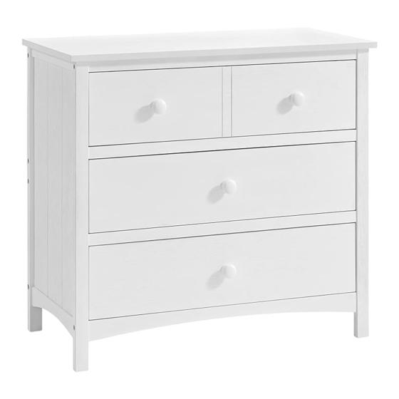
Sommaire des Matières pour OXFORD BABY 42533
- Page 1 ASSEMBLY INSTRUCTIONS CASTLE HILL 3 DRAWER DRESSER Model #42533 90-42533-V-01 1 of 8...
-
Page 2: Commode À 3 Tiroirs Castle Hill
INSTRUCTIONS DE MONTAGE COMMODE À 3 TIROIRS CASTLE HILL Model #42533 90-42533-V-01 1 sur 8... -
Page 3: Outils Nécessaires
Merci pour votre achat ! Retirez toutes les pièces et le matériel de la boîte et posez-les sur une surface de travail recouverte de moquette Ne jetez aucun contenu avant la fin du montage. OUTILS NÉCESSAIRES: TOURNEVIS (non inclus) CLÉ ALLEN (inclus) PIÈCES INCLUSES DANS LE CARTON 1. - Page 4 (L) Clé Allen (1 pièce) (la longueur peut varier) Ne serrez pas complètement tous les boulons avant que toutes les pièces ne soient en place. (veuillez ajouter un 1/2 tour supplémentaire aux boulons lors de l'utilisation de rondelle à ressort après le serrage) 90-42533-V-01 3 sur 8...
- Page 5 (2) comme diagramme. Fixez le rail avant supérieur (4) et le rail inférieur (6) à l’aide du boulon Allen (A), de l’écrou de canon (C), de la rondelle à ressort (D), comme le montre la FIG 1. Serrez tous les boulons avec la clé Allen (L). 90-42533-V-01 4 sur 8...
- Page 6 (3) comme diagramme. Fixez le rail avant supérieur (4) et le rail inférieur (6) à l’aide du boulon Allen (A), de l’écrou de canon (C), de la rondelle à ressort (D), comme le montre la figure 3. Serrez tous les boulons avec la clé Allen (L). 90-42533-V-01 5 sur 8...
- Page 7 à ressort (D). Serrez tous les boulons avec la clé Allen (L). - Fixez le panneau supérieur (1) au panneau arrière en utilisant le boulon Allen (B), la rondelle en croissant (E). Serrez tous les boulons avec la clé Allen (L). 90-42533-V-01 6 sur 8...
- Page 8 à l’arrière avec une vis (H). Serrer avec le tournevis (non inclus). ÉTAPE 4.4 : Fixez le bouton (K) à l’avant du tiroir avec vis à bouton (J). Serrer avec le tournevis (non inclus). 90-42533-V-01 7 sur 8...
- Page 9 ÉTAPE 5 " ASSEMBLAGE DU TIROIR" FIG 5 ÉTAPE 5 : Assemblage la boîte de tiroir à la commode comme indiqué. Complet comme le montre la FIG 5. Merci. 90-42533-V-01 8 sur 8...
-
Page 10: Tools Required
11. Drawer left side (3 pcs) 12. Drawer right side (3 pcs) 13. Drawer back (3 pcs) 14. Drawer bottom panel (3 pcs) 15. Drawer support (3 pcs) Do not fully tighten all Screws until all parts are in place. 90-42533-V-01 2 of 8... - Page 11 (K) Knob (4 pcs) (L) Allen key (1 pc) (length may vary) Do not fully tighten all bolts until all parts are in place. (please add an extra 1/2 revolution to the bolts when using spring washer after tightening) 90-42533-V-01 3 of 8...
- Page 12 - Insert the tenon on the end of Top front rail (4), Drawer rail (5) and Bottom rail (6) into mortise on Left side (2) as diagram. Secure top front rail (4) and bottom rail (6) by using Allen bolt (A), Barrel nut (C), Spring washer (D) as shown in FIG 1. Tighten all bolts with Allen key (L). 90-42533-V-01 4 of 8...
- Page 13 - Insert the tenon on the end of Top front rail (4), Drawer rail (5) and Bottom rail (6) into mortise on Right side (3) as diagram. Secure top front rail (4) and bottom rail (6) by using Allen bolt (A), Barrel nut (C), Spring washer (D) as shown in FIG 3. Tighten all bolts with Allen key (L). 90-42533-V-01 5 of 8...
- Page 14 - Attach Top panel (1) to top front rail and both sides by using Allen bolt (B), Spring washer (D). Tighten all bolts with Allen key (L). - Attach Top panel (1) to back panel by using Allen bolt (B), Crescent washer (E). Tighten all bolts with Allen key (L). 90-42533-V-01 6 of 8...
- Page 15 Attach Drawer back (13) to drawer side ends with Screws (H). Tighten drawer support to drawer front and drawer back with screw (H).Tighten with the Screwdriver (not included). STEP 4.4 : Attach Knob (K) to drawer front with Bolt (J). Tighten with the Screwdriver (not included). 90-42533-V-01 7 of 8...
- Page 16 STEP 5 " ASSEMBLY OF DRAWER" FIG 5 STEP 5 : Assembly drawer box to the dresser as shown. Complete as shown in FIG 5. Thank you. 90-42533-V-01 8 of 8...


