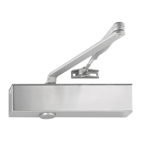
Publicité
Liens rapides
Nicht an Feuer- und Rauchschutztüren erlaubt
Not allowed on fire- and smokeprevention doors
Ne pas permis aux portes de coupe-feu et de fumée
211
EN 2-6
+/-1
222
EN 1-5
+/-1
Bohrungen für Montageplatte gemäß
Beiblatt 1 zur DIN EN 1154
Drillings for mounting plate according
to supplemental sheet 1 DIN EN 1154
Alésage pour platine de montage selon
supplément 1 DIN EN 1154
Bohrungen für Direktmontage
Drillings for direct mounting
Alésage pour montage direct
142
+/-1
211
+/-1
TS-50
0432-CPR-00099-10
EN 1-5/2-6
1
2
m ax .
3 ,5 m m
3
4
optional
Montageplatte gemäß DIN EN 1154
Mounting plate according to DIN EN 1154
Platine de montage selon DIN EN 1154
Montage platte
Mountin g plate
Platine de montage
1
2
m ax .
3 ,5 m m
3
4
optional
Montageplatte gemäß DIN EN 1154
Mounting plate according to DIN EN 1154
Platine de montage selon DIN EN 1154
Montage platte
Mountin g plate
Platine de montage
45
45
Papierschablonen können sich durch Luftfeuchtigkeit verändern.
Verbindlich sind daher nur die Maßangaben.
TS-50
Paper templates might distort due to air moisture. Only the indi-
cated measurements are therefore obligatory.
Les gabarits en papier peuvent avoir des dimensions modifiées
par l'humidité de l'air. Seules les côtes mentionées doivent être
respectées.
160
Türschließergröße
ECO Schulte GmbH & Co. KG
Door closer size
Iserlohner Landstraße 89
17
Force de ferme porte
D-58706 Menden
1
TS-50
2
EN 1-5
3
EN 1154:1996+A1:2002 /
4 8
1-5
1 1
3
4
AC:2006
5
5
2
1
7
2
SW10
1
5
2
1
7
1
SW10
2
2
ECO Schulte GmbH & Co. KG • Iserlohner Landstraße 89 • D-58706 Menden • Tel. +49 23 73 / 92 76 - 0 • FAX +49 23 73 / 92 76 - 40 • info@eco-schulte.de • www.eco-schulte.de
100
Max. Türbreite
Umdrehungen
Türschließergröße
Max. Türbreite
Umdrehungen
Max. door width
Rotations
Door closer size
Max. door width
Rotations
Largeur de porte max.
Rotations
Force de ferme porte
Largeur de porte max.
Rotations
750 mm
-5
2
850 mm
850 mm
-2
3
950 mm
TS-50
950 mm
0
4
1100 mm
EN 2-6
1100 mm
3
5
1250 mm
1250 mm
7
6
1400 mm
6
4
1
2
90°
8
SK/CF/FF
X 2
m
0 m
1 2 5
X 1
m m
7 5 0
2
180°-0°
SG/CS/VF
6
90°
1
2
4
3
8
SK/CF/FF
X 2
m
0 m
X 1
1 2 5
m m
7 5 0
170°-0°
SG/CS/VF
2,5
4,2 (M5)
max. 12
Normalmontage
Bandseite
Standard mounting
pull side
Montage normal
côté paumelles
DIN links / left / gauche
Für die Montage dürfen ausschließlich Originalteile des Herstellers verwendet werden. Die Montagearbeiten müssen gemäß Anleitung von
einer qualifizierten Person durchgeführt werden. Bei Nichtbeachtung entfällt jeglicher Garantieanspruch. Diese Anleitung ist vom Monteur
nach der Montage an den Betreiber weiterzugeben!
-5
Only original parts have to be used. The assembly has to be made by a qualified person according to the mounting instruction. In case of
-2
non-respect the guarantee is invalid. This instruction is to be handed over to the operator by the fitter after assembly!
0
Impérativement utiliser la notice de montage fournie par le fabricant. La mise en œuvre et le montage doivent être exécutés par du personnel
3
qualifié. Le non respect de ces règles annule catégoriquement tout droit de garantie. Cette instruction est à remettre par le poseur
7
à l'exploitant après montage.
9
1
3
10°-0°
ES/LS/CF
11
>
EN 3
optional, as option, en option
9
1
10°-0°
ES/LS/CF
11
optional, as option, en option
optional, as option, en option
>
EN 3
10
12
10
12
Publicité

Sommaire des Matières pour Eco Newton TS-50
- Page 1 7 5 0 170°-0° SG/CS/VF ECO Schulte GmbH & Co. KG • Iserlohner Landstraße 89 • D-58706 Menden • Tel. +49 23 73 / 92 76 - 0 • FAX +49 23 73 / 92 76 - 40 • info@eco-schulte.de • www.eco-schulte.de...
- Page 2 7 5 0 170°-0° SG/CS/VF ECO Schulte GmbH & Co. KG • Iserlohner Landstraße 89 • D-58706 Menden • Tel. +49 23 73 / 92 76 - 0 • FAX +49 23 73 / 92 76 - 40 • info@eco-schulte.de • www.eco-schulte.de...


