
Manuels Connexes pour Marinelli Cucine BLC 1M90 P INOX


Sommaire des Matières pour Marinelli Cucine BLC 1M90 P INOX
- Page 1 NOTICE DE MONTAGE DE LA CUISINE ALL IN LAQUEE BLC 1M90 P INOX INSTRUCTION FOR THE ASSEMBLY OF THE KITCHEN ALL IN LAQUEE BLC 1M90 P INOX...
- Page 2 ASSEMBLY INTRODUCTION INTRODUCTION AU MONTAGE KITCHEN CONFIGURATION L+R / CONFIGURATION DE LA CUISINE In this leaflet, the kitchen is presented in its right version with the fridge cabinet on the left side, and the sink to the right one. However, the following elements are all reversible to allow assembly of the fridge cabinet either on the left or right side, and consequently all the elements of the kitchen: -Reversible wall unit front door (1)
- Page 3 2. BASE 60 1 DRAWER + 1 DOOR AND WALL UNIT 60 MEUBLE BAS 40 1 TIROIR + 1 PORTE ET MEUBLE HAUT 40 1 PORTE FOTO/PHOTO 25 FOTO/PHOTO 26 - For both the base unit 60 (1 drawer+1 front) and the wall unit 60 unscrew the base of the hinges from the cabinet (pic.
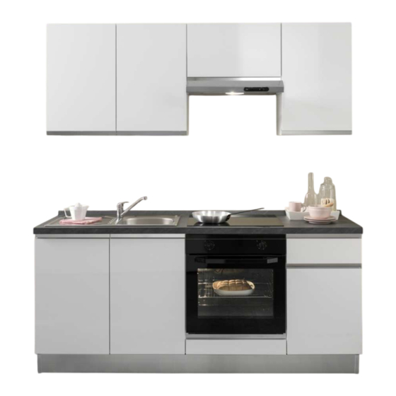
- Page 4 Notice Instructions 190 cm 40 cm 80 cm Hotte /Hood Wall Unit 80 Wall unit 40 Profil d'étanchéité pour plan de travail Back splash Fireresisitqantworktop 4 cm Zoccolo 40 cm 80 cm Meuble bas 40 Meuble bas Meuble 1 Tiroir - 1 Porte Sink base unti Oven base 60 cm Base 40...
- Page 5 Notice de montage de la cuisine LISTE DES ELEMENTS PRÉ-ASSEMBLÉS : QUINCAILLERIE N° 4 Pieds B - Rails de suspension pour meubles hauts de 2m à N° 7 Poignée + 20 vis recouper C - Meuble haut 60 cm. (intégrer dans le N°...
- Page 6 PHASE N° 1 To position the hanging bar, please sign on the wall from flooring a line at 210cm height , and 200 cm lenght . Lean the hanging bar on the sign of the wall, (B) then make the holes every 30 cm of the bar .
- Page 7 PHASE N° 2 Adjust the hooks (g) of the wall units (they should hang out of the furniture 1 cm) then hook the wall unit to the hanging bar (B)in the following order (C-E) see page 2. To regulate the position of the wall unit, operate the regulator (r).
- Page 8 PHASE N° 3 Bubble Level / Niveau Wall Hook the wall unit 60 (C) to the hanging bar (B). Level the top part of the wall unit regulating the hooks as explained in phase 4 Accrocher le meuble haut 60 (C ) à la cornière (B).
- Page 9 PHASE NO. 4 – ASSEMBLY OF THE FREE STANDING HOOD Please refer to the instruction manual of the hood PHASE NO. 4B - ASSEMBLY OF THE HOOD WALL UNIT Please refer to the instruction manual of the hood PHASE NO. 4 - MONTAGE DE LA HOTTE (D) Attention : notice d'utilisation de la hotte dans le colis de la HOTTE PHASE NO.
- Page 10 PHASE N° 5 Hook the wall unit 60(D) and he wall unit 90 (E) to the hanging bar (B). Then level the wall unit 90 Parete / Mur (E) and 60 (D) adjusting the hooks as shown in phase 4. Accrocher le meuble haut 60 avec hotte integree(D) à...
- Page 11 PHASE N° 6 Wall / Mur Assembly of the shelves Position one side of the shelf , inserting the shelf support into the hole as shown in the detail pictures (p) Then push down the opposite side of the shelf to hook the other shelf support to the furniture.
- Page 12 PHASE N° 7 Lean the base (I) on the side , then insert Wall / Mur the supports to the bottom of the furniture as shown in detail 2 . Now stand up the base , and level the height (operating on the supports as shown in phase 2) Coucher le meuble bas (I) sur le côté...
- Page 13 PHASE N° 8 Wall / Mur Take out the oven from its compartment . Lean the base unit on the side and insert the supports as done before ( see pag 9 detail 2) Stand up the base unit, and pulli t together with the next base (I ) Level the base unit operating the supports as shown in phase 2 (page 4) Insert the coupling screw (6), then scew tightly paying attention to the screws already fitted in the furniture.
- Page 14 PHASE N° 9 Lean the sink base unit (K) and insert the support as done Wall / Mur previously ( see page 9 detail 2) Stand up the base unit then pull it together with the oven base unit (J), then level it with the oven base unit base operating on the supports as done in phase 2 (page 4) Now insert the coupling screw into the hole (7), the screw tightly paying attention to the screw already fitted in the...
- Page 15 PHASE N° 10 Place the worktop on sawhorse as shown (L) Place the fixing hooks (gl) on the internal edge of the sink (N). See detail 14. Poser le plan de travail (L) déjà percé sur deux tréteaux. Appliquer les bandes de silicone autour de l'évier (voir détail 13).
- Page 16 PHASE N° 11 Position the sink (L), into the biggest hole as shown in the picture, then rotate the hooks towards the outside of the sink (N) . Tighten the hooks as shown in detail 15 . Clsmp the screws Serrer tous les crochets NOTE: we strongly recommend to involve a plumber in the fitting of the mixer tap and the drain pipe Mettre l’évier sur le plan de travail (L), tourner les crochets vers l’extérieur de l’évier (N) .
- Page 17 PHASE N° 12 Wall / Mur Apply on both internal edge left and right of the sink (K) 2 L shaped plates(sq) through screws 4x18 mm .Look detail 21 Lean the worktop (L) complete with sink on the bases as shown in the picture Fix the worktop (L) to the bases through L shaped plates (sq) using screws 4x18 mm.,...
- Page 18 PHASE N° 13 Before fixing the angular bracket of the backsplash, profile take off the terminal of the backsplash profile with a screw driver (as shown in detail 6 ) The backsplash (O) is fixes Parete / Mur on the back part of the worktop(L) as follows : -Prior fixing the backsplash , it is advisable to spread a layer of silicon on its length -Hook the backsplash to the angular bracket (ca) (see detail 6);...
- Page 19 PHASE N° 14 Position the kick plate (P), (Q) and(R), in front of the base .Slide the spring hooks(gm) into its housing . Lift Wall / Mur Kickplatesectionwithhook/ Section duplinthe aveccrochet the long kick plate (P) mt. 1,9 and push to clip it to the base supports .
- Page 20 PHASE N° 15 - To fix the handle on the base 60 (1 drawer +1 pull out ) and that of the wall unit 60 1 front, complete the handle holes applying a piece of wood to exterior of the front door as shown in picture 20 to protect the finishing, then pierce the pre- pierced holes from the inside.
- Page 21 PHASE N° 16 Picture 9 Dessin 9 To adjust the position of the front doors, WallUnit / Meublehaut Top/bottom tighten or ease screws (z) positioning the hinges as desired. To regulate depth operate screw (w) See picture 9. Pour régler les portes en hauteur, désserrer les vis (z) et pousser les bases de charnières vers le haut ou vers le bas.
- Page 22 Advice for correct use of the kitchen Dear Customer, Thank you for having chosen a product Marinelli Cucine . This kitchen has been manufactured with top quality materials, in compliance with EU law. Here below some suggestion to maximize life- span of this product: -The predominant material used to manufacture this kitchen is a particular wooden melamine agglomerate which has a low tolerance to humidity.