Publicité
Liens rapides
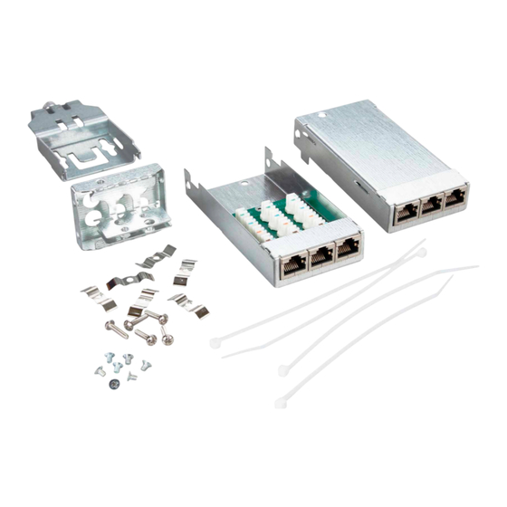
DCCS2 C6
MTC6
A
130D2CM6-E
Montagehinweis für den Installateur
de
Mounting note for the installer
en
Notice d'installation pour l'installateur
fr
A |Kabelkonfektion / Cable preparation / Préparation du câble
1
2
150 mm
5.906 in.
90 mm
3.543 in.
B |Kabelmontage / Cable termination / Raccordement du câble
1
2
3
5
6
1
2
4
4
5
·
METZ CONNECT GmbH | Im Tal 2 | 78176 Blumberg | Germany
Phone +49 7702 533-0 | Fax +49 7702 533-433
Weitere technische Dokumentationen siehe / For more technical documentation see/ Plus de documentation technique à télécharger sur www.metz-connect.com
HINWEIS / NOTE / NOTICE
de
Anschlussfehler vermeiden!
Vor dem Anschluss Montageanleitung
sorgfältig lesen!
en
Avoid connection errors!
Read installation instructions carefully
before connecting!
Eviter des erreurs
fr
de raccordement !
A lire attentivement avant de procéder au
raccordement !
3
3
5
1
6
2
4
3
6
de
DEUTSCH
WARNUNG
Achtung!
Ausstecken (Ziehen des RJ45-Steckers) nur bei
zuvor ausgeschaltetem Gerät ohne Spannung.
Ausstecken, insbesondere wiederholtes Aus-
stecken unter Spannung (bei Verwendung von
Power over Ethernet PoE) kann zu Schäden an
den Kontakten der RJ45-Steckverbindung führen.
HINWEIS
Unsere Anschlusssysteme und Verteilerprodukte
für strukturierte Gebäudeverkabelungen entspre-
chen den gültigen Normen ISO/IEC 11801, EN
50173-1 und IEC 60603-7. Bei Komplettierung
der
Anschlüsse
muß
tagebetrieb prüfen und beachten, dass nur
Patch- und Anschlusskabel, die die EN-/ IEC-
Normen erfüllen, verwendet werden. Lassen Sie
sich ggf. vom Lieferanten den Nachweis geben,
dass die eingesetzten Kabel und Stecker der
Norm entsprechen. Die Verwendung von nicht
normgerechten Komponenten bedeutet den
Verlust der Mängelrechte auch innerhalb der
Lieferkette unserer Produkte. Die Installation ist
nur von Fachpersonal durchzuführen. Hierbei
sind die Sicherheitsanforde rungen nach EN
60950 zu beachten. Bitte beachten Sie auch,
dass keine starken mechanischen Ein wirkungen
und Bean spruchungen beim Ein- und Ausstecken
des Benutzerkabels nach oben, unten oder seit-
lich auf den elektrischen Kontaktbe reich der
Steckverbindung (z. B. durch Ziehen am Kabel u.
a.) erfolgen. Für dadurch entstehende Schäden
haften wir nicht. Bitte übergeben Sie diesen
Hinweis auch an den Endverbraucher.
A |Kabelkonfektion
Abb. 1:
Kunststoffmantel vom Hauptkabel ca. 150 mm
und von den Einzelkabeln 90 mm abisolieren.
Abb. 2:
Einzelkabel entsprechend dem Kabelaufdruck
1
separieren.
3
5
Abb. 3:
Kabelaufnahme mit Portzuordnung.
2
4
6
A |Kabelmontage
Abb. 1:
Geflechtschirm der einzelnen Kabel nach
hinten über den Mantel legen und Einzelkabel
in die Kabelaufnahme einfädeln.
Abb. 2:
Schirmgeflecht auf der Rückseite der Kabelauf-
nahme abschneiden.
Abb. 3:
Zugentlastung mittels Kabelbinder herstellen.
Abb. 4:
Schirmanschlussschellen Ê und Ë für die
Einzelkabel 1, 3 und 5 aufsetzen und fest
schrauben, danach für die Einzelkabel 2, 4
und 6.
Abb. 5:
Kabelablage auf Kaberlaufnahme stecken.
Zugentlastung für Hauptkabel mittels Kabel-
binder herstellen.
Abb. 6:
Kabelaufnahme in das Gehäuseunterteil
einführen. Kabelaufnahme mit Gehäuseunter
teil verschrauben.
Anschlussbelegung
PIN Nr.
T568A
1
WH-GN
2
GN
3
WH-OG
4
BU
5
WH-BU
6
OG
7
WH-BN
8
BN
en
ENGLISH
WARNING
Attention!
Before unplugging the RJ45 plug make sure that
the device is switched off and is no longer ener-
gised. Unplugging, particularly repeated unplug-
ging of an energised device (when using Power
over Ethernet PoE) may damage the contacts of
the RJ45 plug connection.
NOTE
Our termination systems and patch products for
generic cabling meet the active standards ISO/IEC
11801, EN 50173-1 und IEC 60603-7. The user or
installer has to check and take care to use solely
der
Verwender/Mon-
patch and termination cables that meet the EN-/
IEC standards when completing the installation.
If necessary ask your supplier to certify that the
installed cables and plugs meet the standards.
The use of non-standard components means the
loss of rights accruing from defects even within
the supply chain of our products. Installation only
by qualified personnel. Electrical Safety per EN
60950. Furthermore, please pay attention that
the electric contact area of the plug connection is
not exposed to high mechanical effects or strain
(e.g. by pulling the cable etc.) when the user
cable is plugged in or out upwards, downwards
or sidewards. We do not take over liability for any
damage. Please give this note to end users, too.
A |Cable preparation
Fig. 1:
Remove about 150 mm / 5.906 inches of the
main cable's plastic sheath and
90 mm / 3.543 inches of the single cables.
Fig. 2:
Separate the single cables according to port
number printed on the sheath of each cable.
Fig. 3:
Cable bracket with port assignment.
A |Cable termination
Fig. 1:
Fold braided shield of each single cable back
ward over the sheath and push the cables
through the entries of the bracket.
Fig. 2:
Cut the braided shield at the back of the cable
bracket.
Fig. 3:
Use cable ties for strain relief.
Fig. 4:
Attach the shield connection clamps Ê and Ë
for single cables 1, 3 and 5 and screw them
down, do the same for cables 2, 4 and 6.
Fig. 5:
Plug the cable tray to the cable bracket. Use
cable tie for strain relief of the main cable.
Fig. 6:
Insert the cable bracket into the lower housing
part. Screw the cable bracket to the lower
housing part.
PIN assignment
T568B
No.
T568A
WH-OG
1
WH-GN
OG
2
GN
WH-GN
3
WH-OG
BU
4
BU
WH-BU
5
WH-BU
GN
6
OG
WH-BN
7
WH-BN
BN
8
BN
fr
FRANÇAIS
AVERTISSEMENT
Attention!
Débrancher la fiche RJ45 seulement après avoir
èteint l'appareil et l' avoir mis hors tension. Un
débranchement sous tension, surtout répété,
peut
causer des dommages aux contacts de la con-
nexion
RJ45 en cas d'utilisation Power over Ethernet
(PoE).
NOTICE
Nos systèmes de raccordement et produits
de distribution pour le câblage générique
sont conformes aux normes en vigueur EN
50173-1:2007 et IEC 60603-7. Il est nécessaire
que l'utilisateur ou l'entreprise d'installati-
on vérifient et tiennent compte d'employer
uniquement les cordons de brassage et de
raccordement qui répondent aux normes EN/
IEC. Il est conseillé de se faire certifier cette
conformité aux normes par le fournisseur des
câbles et connecteurs utilisés. L'utilisation de
composants qui ne sont pas conformes aux
normes ci-dessus entraînera la perte des droits
de réclamation aussi dans la chaîne de livraison
de nos produits. L'installation ne peut être
effectuée par des spécialistes en tenant compte
des demandes de sécurité selon EN 60950.
Prière de faire attention qu'il n'y a pas de forts
actions et efforts agissant vers le haut, vers le
bas ou vers le côté dans la région électrique du
contact du connecteur en insérant ou en sort-
ant le câble client (p. ex. en tirant sur le câble).
Nous n'assumons pas de responsabilité pour
des dégâts qui en résultent. Prière de donner
ces indications aussi à l'utilisateur final.
A |Préparation du câble
Fig. 1:
Dénuder la gaine plastique du câble principal
d'environ 150 mm et dénuder les câbles
individuels de 90 mm.
Fig. 2:
Séparer les câbles individuels selon l'impres-
sion sur le câble.
Fig. 3:
Logement de câbles avec affectation des ports.
A |Raccordement du câble
Fig. 1:
Plier le treillis de blindage de chaque câble
individuel en arrière sur la gaine et les insérer
au logement.
Fig. 2:
Couper le treillis de blindage derrière le
logement de câbles.
Fig. 3:
Utilisier des attaches-câbles pour la décharge
de traction.
Fig. 4:
Poser les colliers pour le raccordement du
blindage Ê et Ë pour les câbles individuels 1, 3
et 5 et les visser, ensuite répéter la procédure
pour les câbles individuels 2, 4 et 6.
Fig. 5:
Enficher le repos-câbles sur le logement de
câbles. Utiliser un attache-câble pour la
décharge de traction du câble principal.
Fig. 6:
Introduire le logement de câbles dans la partie
inférieure du boîtier. Visser le logement et la
partie inférieure du boîtier.
Affectation des contacts
T568B
Numéro du contact
T568A
T568B
WH-OG
1
WH-GN
WH-OG
OG
2
GN
OG
WH-GN
3
WH-OG
WH-GN
BU
4
BU
BU
WH-BU
5
WH-BU
WH-BU
GN
6
OG
GN
WH-BN
7
WH-BN
WH-BN
BN
8
BN
BN
Publicité

Manuels Connexes pour Metz Connect DCCS2 C6A MTC6


Sommaire des Matières pour Metz Connect DCCS2 C6A MTC6
- Page 1 WH-BN WH-BN METZ CONNECT GmbH | Im Tal 2 | 78176 Blumberg | Germany Phone +49 7702 533-0 | Fax +49 7702 533-433 Weitere technische Dokumentationen siehe / For more technical documentation see/ Plus de documentation technique à télécharger sur www.metz-connect.com...
- Page 2 Fig. 2: Visser le couvercle. METZ CONNECT GmbH | Im Tal 2 | 78176 Blumberg | Germany Phone +49 7702 533-0 | Fax +49 7702 533-433 Weitere technische Dokumentationen siehe / For more technical documentation see/ Plus de documentation technique à télécharger sur www.metz-connect.com...