Table des Matières
Publicité
Les langues disponibles
Les langues disponibles
Liens rapides
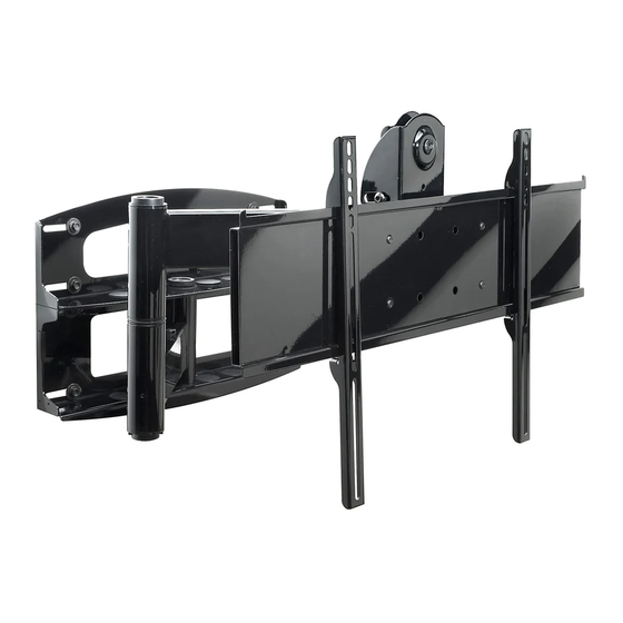
Installation and Assembly
Swivel Arm for 37" - 60" Plasma Screens
- Universal Articulating
Models: PLA 60-UNL, PLA 60-UNL-S,
PLA 60-UNLP, PLA 60-UNLP-S,
PLAV 60-UNL, PLAV 60-UNL-S,
PLAV 60-UNLP, PLAV 60-UNLP-S
RTPLA 60, RTPLA 60-S, RTPLA UN7,
RTPLA UN7S, D-FPA-320, D-FPA-320S
This product is UL Listed. It must be
installed by a qualified professional
R
installer.
Maximum UL Load Capacity: 175 lb (79 kg)
Publicité
Table des Matières

Sommaire des Matières pour Peerless Industries PLA 60-UNL
- Page 1 Installation and Assembly Models: PLA 60-UNL, PLA 60-UNL-S, - Universal Articulating PLA 60-UNLP, PLA 60-UNLP-S, Swivel Arm for 37" - 60" Plasma Screens PLAV 60-UNL, PLAV 60-UNL-S, PLAV 60-UNLP, PLAV 60-UNLP-S RTPLA 60, RTPLA 60-S, RTPLA UN7, RTPLA UN7S, D-FPA-320, D-FPA-320S This product is UL Listed.
-
Page 2: Tools Needed For Assembly
NOTE: Read entire instruction sheet before you start installation and assembly. WARNING • Do not begin to install your Peerless product until you have read and understood the instructions and warnings contained in this Installation Sheet. If you have any questions regarding any of the instructions or warnings, please call Peerless customer care at 1-800-865-2112. - Page 3 D-FPA-320S RTPLA UN7 RTPLA UN7S RTPLA 60 RTPLA 60-S Before you start make sure all parts PLA 60-UNL PLA 60-UNL-S PLAV 60-UNL PLAV 60-UNL-S listed are included with your product. PLA 60-UNLP PLA 60-UNLP-S PLAV 60-UNLP PLAV 60-UNLP-S DESCRIPTION QTY. PART #...
- Page 4 Before you begin, make sure all parts shown are included with your product. RTPLA UN7 RTPLA UN7S RTPLA 60 RTPLA 60-S PLA 60-UNL PLA 60-UNL-S PLA 60-UNLP PLA 60-UNLP-S Adapter Bracket Parts List PLAV 60-UNL PLAV 60-UNL-S PLAV 60-UNLP PLAV 60-UNLP-S...
- Page 5 Security Adapter Bracket Fasteners M4 x 12 mm (6) M5 x 12 mm (4) M6 x 12 mm (4) 510-1079 520-1064 520-1050 M8 x 15 mm (6) M6 x 20 mm (4) 520-1068 520-9554 M5 x 25 mm (4) 520-1122 M4 x 25 mm (4) M6 x 25 mm (4) M8 x 25 mm (4)
-
Page 6: Installation To Wood Stud Wall
Place wall plate on wall as a template. The top mounting slots should be located .36" above the desired screen center for PLA 60-UNL, PLA 60-UNL-S, PLA 60-UNLP, PLA 60-UNLP-S, RTPLA 60 RTPLA 60-S and .43" below the desired screen center for PLAV 60-UNL, PLAV 60-UNL-S, PLAV 60-UNLP, PLAV 60-UNLP-S, RTPLA UN7, RTPLA UN7S, D-FPA-320, and D-FPA-320S. - Page 7 The top mounting slots should be located .36" above the desired screen center for PLA 60-UNL, PLA 60-UNL-S, PLA 60-UNLP, RTPLA 60, PLA 60-UNLP-S and RTPLA 60-S and .43" below the desired screen center for PLAV 60-UNL, PLAV 60-UNL-S, PLAV...
- Page 8 WARNING • If you are uncertain that product is properly installed, call customer care. Note: There are five mounting positions. The center position is shown (right). Slide washer (J) over wall support arm axle (D). Next, insert plastic cap (N) into axle. Then, insert holding pin (M) into axle.
- Page 9 Attach two pieces of vinyl trim (E) to wall plate (A). Next, attach one piece of vinyl trim to bottom of swivel box on arm assembly (C). Insert one finishing cap (L) into each unused hole of wall plate (A). SWIVEL BOX Insert and tape carriage bolt (I) into top hole of pitch-roll assembly (B).
- Page 10 WARNING • Use an assistant or mechanical lifting equipment to safely lift and position the plasma TV. Insert two M10 screws (F) into swivel box on arm assembly (C) as shown. Leave approx. 1/4" of exposed thread. SWIVEL BOX .25" Hook tilt-roll assembly (B) onto M10 screws (F).
- Page 11 Installing Adapter Brackets WARNING • Tighten screws so adapter brackets are firmly attached. Do not tighten with excessive force. Overtightening can cause stress damage to screws, greatly reducing their holding power and possibly causing screw heads to become detached. Tighten to 40 in. • lb (4.5 N.M.) maximum torque. •...
- Page 12 For Flat Back Screen Refer to Screen Compatibility Chart to determine the proper fastener to use. Visit www.peerlessmounts.com/2 for a full screen compatibility chart for this mount. Begin with the shortest length screw, hand thread through multi-washer and adapter bracket into screen as shown below.
-
Page 13: Mounting And Removing Flat Panel Screen
Mounting and Removing Flat Panel Screen WARNING • Always use an assistant or mechanical lifting equipment to safely lift and position the plasma television. Refer to mount instruction sheet for attachment of adapter bracket to mount. Hook adapter brackets (BB or CC) onto adapter bracket (AA), then slowly swing screen in as shown. Turn screws clockwise at least six times to prevent screen from being removed as shown in detail 4. - Page 14 10.1 counterclockwise with 10 mm allen wrench (V). fig. 9.1 SOCKET SCREW fig. 10.1 14 of 42 ISSUED: 06-05-06 SHEET #: 202-9141-7 05-06-08 © 2007, Peerless Industries, Inc. All rights reserved. All other brand and product names are trademarks or registered trademarks of their respective owners.
-
Page 15: Installation Et Montage - Support Mural Articulé Universel Pour Écrans Plasma De 37 À 60 Po
Modèles : PLA 60-UNL, PLA 60-UNL-S, Installation et montage - Support mural articulé PLA 60-UNLP, PLA 60-UNLP-S, universel pour écrans plasma de 37 à 60 po PLAV 60-UNL, PLAV 60-UNL-S, PLAV 60-UNLP, PLAV 60-UNLP-S RTPLA 60, RTPLA 60-S, RTPLA UN7, RTPLA UN7S, D-FPA-320, D-FPA-320S Ce produit est homologué... -
Page 16: Outils Nécessaires Au Montage
Remarque : lisez entièrement la fiche d’instructions avant de commencer l’installation et l’assemblage. AVERTISSEMENT • Ne commencez pas à installer votre produit Peerless avant d’avoir lu et assimilé les instructions et les mises en garde contenues dans cette fiche d’installation. Pour toute question concernant les instructions ou les mises en garde, appelez le service à... -
Page 17: Liste Des Pièces Du Support Mural
D-FPA-320S RTPLA 60 RTPLA 60-S support mural RTPLA UN7 RTPLA UN7S PLA 60-UNL PLA 60-UNL-S PLAV 60-UNL PLAV 60-UNL-S PLA 60-UNLP PLA 60-UNLP-S PLAV 60-UNLP PLAV 60-UNLP-S Cant.Nº de pieza Nº de pieza Nº de pieza Nº de pieza Descripción... -
Page 18: Liste Des Pièces
RTPLA UN7 RTPLA UN7S RTPLA 60 RTPLA 60-S Avant de commencer, veillez à ce que toutes les pièces énumérées soient incluses. PLA 60-UNL PLA 60-UNL-S PLA 60-UNLP PLA 60-UNLP-S Liste des pièces PLAV 60-UNL PLAV 60-UNL-S PLAV 60-UNLP PLAV 60-UNLP-S Description Qté... -
Page 19: Fixations De Sécurité Du Support Adaptateur
Fixations de sécurité du support adaptateur M4 x 12 mm (6) M6 x 12 mm (4) M5 x 12 mm (4) M8 x 15 mm (6) 510-1079 520-1050 520-1064 M6 x 20 mm (4) 520-1068 520-9554 M5 x 25 mm (4) 520-1122 M8 x 25 mm (4) M4 x 25 mm (4) -
Page 20: Installation Sur Des Murs À Montants En Bois
Posez la plaque murale sur le mur et utilisez-la comme gabarit. Les fentes de montage supérieures doivent être situées à 0,36 po au-dessus de l’endroit souhaité pour le centre de l’écran pour les modèles PLA 60-UNL, PLA 60-UNL-S, PLA 60-UNLP, RTPLA 60, PLA 60-UNLP-S RTPLA 60-S,... -
Page 21: Installation À Uan Mur En Béton
Les fentes de montage supérieures doivent être situées à 0,36 po au-dessus de l’endroit souhaité pour le centre de l’écran pour les modèles PLA 60-UNL, PLA 60-UNL-S, PLA 60-UNLP, PLA 60-UNLP-S et RTPLA 60-S et à 0,43 po sous l’endroit souhaité pour le centre du moniteur pour les modèles PLAV 60-UNL,... - Page 22 AVERTISSEMENT • Si vous n’êtes pas certain que le produit est installé correctement, appelez le service à la clientèle. Remarque : Il y a cinq positions de montage possibles. La position centrale est illustrée (à droite). Faites glisser la rondelle (J) par dessus l’axe du support mural (D).
- Page 23 Attachez deux bordures en vinyle (E) à la plaque murale (A). Attachez ensuite une bordure en vinyle au bas de la boîte de rotation du bras articulé (C). Insérez un embout de finition (L) dans chaque trou inutilisé de la plaque murale (A). BOÎTE DE ROTATION Insérez le boulon de carrosserie (I) dans l’orifice supérieur support inclinable et rotatif (B) et maintenez-le avec du ruban adhésif.
- Page 24 AVERTISSEMENT • Pour lever et positionner le téléviseur plasma en toute sécurité, faites-vous aider par une autre personne ou utilisez un dispositif de levage mécanique. Insérez deux vis M10 (F) dans la boîte de rotation du bras articulé (C) comme illustré. Laissez environ ¼ po de filetage exposé.
-
Page 25: Installation Des Supports Adaptateurs
Installation des supports adaptateurs AVERTISSEMENT • Serrez les vis de manière à ce que les supports adaptateurs tiennent solidement en place. N’exercez pas une force excessive. Un serrage excessif peut endommager les vis, réduire considérablement leur capacité de support et, éventuellement, faire tomber les têtes de vis. - Page 26 Pour les écrans à dos plat Le Tableau de compatibilité avec l’écran permet de déterminer quelle fixation utiliser. Visitez www.peerlessmounts.com/2 pour obtenir un tableau de compatibilité pour ce support. Commencez par la vis la plus courte et vissez-la manuellement à l’écran en la faisant passer à travers la rondelle tout usage et le support adaptateur, comme indiqué...
-
Page 27: Montage Et Démontage D'un Écran Plat
Montage et démontage d’un écran plat AVERTISSEMENT • Pour lever et positionner le téléviseur plasma en toute sécurité, faites-vous toujours aider par une autre personne ou utilisez un dispositif de levage mécanique. Veuillez vous reporter à la feuille d’instructions pour la fixation du support adaptateur au support. Accrochez les supports adaptateurs (BB ou CC) au support adaptateur (AA), puis faites pivoter lentement l’écran comme illustré. - Page 28 à l’aide d’une clé hexagonale de 10 mm (V). fig. 10.1 28 of 42 ISSUED: 06-05-06 SHEET #: 202-9141-7 05-06-08 © 2007, Peerless Industries, Inc. All rights reserved. All other brand and product names are trademarks or registered trademarks of their respective owners.
- Page 29 Modelos: PLA 60-UNL, PLA 60-UNL-S, Instalación y ensamblaje – Brazo articulador de PLA 60-UNLP, PLA 60-UNLP-S, giro universal para pantallas de plasma de 37" - 60" PLAV 60-UNL, PLAV 60-UNL-S, PLAV 60-UNLP, PLAV 60-UNLP-S RTPLA 60, RTPLA 60-S, RTPLA UN7,...
-
Page 30: Herramientas Necesarias Para El Ensamblaje
Nota: Lea la hoja de instrucciones completa antes de comenzar la instalación y el ensamblaje. ADVERTENCIA • No comience a instalar su producto de Peerless hasta haber leído y entendido las instrucciones y las advertencias contenidas en la Hoja de Instalación. Si tiene alguna pregunta acerca de cualquiera de las instrucciones o las advertencias, por favor, llame a Servicio al Cliente de Peerless al 1-800-865-2112. - Page 31 RTPLA UN7 RTPLA UN7S que su producto incluye todas las RTPLA 60 RTPLA 60-S piezas indicadas en la lista. PLA 60-UNL PLA 60-UNL-S PLAV 60-UNL PLAV 60-UNL-S PLA 60-UNLP PLA 60-UNLP-S PLAV 60-UNLP PLAV 60-UNLP-S Cant.Nº de pieza Nº de pieza Nº...
- Page 32 Antes de comenzar, asegúrese de que su producto contiene todas las partes que se muestran RTPLA UN7 RTPLA UN7S RTPLA 60 RTPLA 60-S Lista de piezas del soporte de pared PLA 60-UNL PLA 60-UNL-S PLA 60-UNLP PLA 60-UNLP-S PLAV 60-UNL PLAV 60-UNL-S PLAV 60-UNLP PLAV 60-UNLP-S Descripción...
- Page 33 Fijaciones de seguridad para los soportes adaptadores M4 x 12 mm (6) M6 x 12 mm (4) M5 x 12 mm (4) M8 x 15 mm (6) 510-1079 520-1050 520-1064 M6 x 20 mm (4) 520-1068 520-9554 M5 x 25 mm (4) 520-1122 M8 x 25 mm (4) M4 x 25 mm (4)
-
Page 34: Instalación En Una Pared Con Montantes De Madera
.36" sobre el punto donde quiere que quede el centro de la pantalla en el caso de los modelos PLA 60-UNL, PLA 60-UNL-S, PLA 60-UNLP, RTPLA 60, PLA 60-UNLP-S, RTPLA 60-S, RTPLA UN7, RTPLA UN7S, D-FPA-320, y D-FPA-320S .43" bajo el punto donde quiere que quede el centro de la pantalla en el caso de los modelos PLAV 60-UNL, PLAV 60-UNL-S, PLAV 60-UNLP, PLAV 60- UNLP-S RTPLA UN7, RTPLA UN7S, D-FPA-350, y D-FPA-350S. - Page 35 .36" sobre el punto donde quiere que quede el centro de la pantalla en el caso de los modelos PLA 60-UNL, PLA 60-UNL-S, PLA 60-UNLP, RTPLA 60, PLA 60-UNLP-S y RTPLA 60-S y .43" bajo el punto donde quiere que quede el...
- Page 36 ADVERTENCIA • Si no está seguro de que el producto esté bien instalado, llame a Servicio al Cliente. Nota: Hay cinco posiciones de instalación. Se muestra la posición central (derecha). Deslice la arandela (J) sobre el eje del brazo del soporte de pared (D).
- Page 37 Adhiera dos pedazos del ribete de vinilo (E) a la placa de pared (A). Luego adhiera un pedazo del ribete de vinilo a la parte inferior de la caja giratoria del armazón del brazo (C). Inserte una capa plástica de acabado (L) en cada agujero que no haya utilizado de la placa de pared (A). CAJA GIRATORIA Inserte y adhiera, con un pedazo de cinta adhesiva, el perno de cabeza redonda (I) al armazón de inclinación y giro (B).
- Page 38 ADVERTENCIA • Cuente con un asistente o con un equipo mecánico de izar para levantar y colocar el televisor de plasma con más seguridad. Inserte dos tornillos M10 (F) en la caja giratoria del armazón del brazo (C), como se muestra. Deje aproximadamente 1/4"...
- Page 39 Instalación de los soportes adaptadores ADVERTENCIA • Apriete los tornillos de manera que los soportes adaptadores se fijen con firmeza. No los apriete con fuerza excesiva. Apretar los tornillos en exceso puede causarles daño por forzarlos, y puede disminuir significativamente su fuerza de fijación y podría causar el desprendimiento de las cabezas de los tornillos.
- Page 40 Instalación de un televisor que tiene la parte posterior plana Refiérase a la Tabla de compatibilidad de las pantallas para determinar cuáles son los sujetadores adecuados para usarse. Acceda a www.peerlessmounts.com/2 para ver una tabla completa de las pantallas compatibles con este soporte.
-
Page 41: Instalación Y Desinstalación De La Pantalla Plana
Instalación y desinstalación de la pantalla plana ADVERTENCIA • Siempre cuente con un asistente o con un equipo mecánico de izar para levantar y colocar el televisor de plasma con más seguridad. Refiérase a la hoja de instrucciones del soporte para saber cómo fijar el soporte adaptador. Enganche los soportes adaptadores (BB o CC) a la placa de pared (AA) y luego gire la pantalla lentamente hacia dentro, como se muestra. - Page 42 10 mm (V). TORNILLOS fig. 10.1 42 of 42 ISSUED: 06-05-06 SHEET #: 202-9141-7 05-06-08 © 2007, Peerless Industries, Inc. All rights reserved. All other brand and product names are trademarks or registered trademarks of their respective owners.