Continental Fireplaces CDVS600-1N Manuel D'installation Et D'opération
Masquer les pouces
Voir aussi pour CDVS600-1N:
- Instructions d'installation et d'opération (120 pages)
Table des Matières
Publicité
Les langues disponibles
Les langues disponibles
Liens rapides
NATURAL GAS MODELS:
PROPANE GAS MODELS:
SAFETY INFORMATION
WARNING
!
FIRE OR EXPLOSION HAZARD
Failure to follow safety warnings exactly
could result in serious injury, death, or
property damage.
- Do not store or use gasoline or other
fl ammable vapors and liquids in the vicinity of
this or any other appliance.
- WHAT TO DO IF YOU SMELL GAS:
•
Do not try to light any appliance.
•
Do not touch any electrical switch; do not
use any phone in your building.
•
Immediately call your gas supplier from a
neighbour's phone. Follow the gas
supplier's instructions.
•
If you cannot reach your gas supplier, call
the fi re department.
- Installation and service must be performed
by a qualifi ed installer, service agency, or the
supplier.
This appliance may be installed in an aftermarket,
permanently located, manufactured home (USA
only) or mobile home, where not prohibited by
local codes.
This appliance is only for use with the type of gas
indicated on the rating plate. This appliance is
not convertible for use with other gases, unless
a certifi ed kit is used.
INSTALLER:
Leave this manual with the appliance
CONSUMER:
Retain this manual for future reference
Wolf Steel Ltd., 24 Napoleon Rd., Barrie, ON, L4M 0G8 Canada / 103 Miller Drive, Crittenden, Kentucky, USA, 41030
$10.00
CDVS600-1N / CS600-1N
ADD PRODUCT CODE HERE (TRADE GOTHIC LT STD FONT)
CDVS600-1P / CS600-1P
Phone 1 (866) 820-8686 • www.continentalfi replaces.com • ask@continentalfi re.com
INSTALLATION AND
ADD MANUAL TITLE
OPERATION MANUAL
S H
O W
N W
CERTIFIED TO THE CANADIAN AND AMERICAN NATIONAL STANDARDS:
CSA 2.22 AND ANSI Z21.50 FOR VENTED DECORATIVE GAS APPLIANCES
IF INSTALLATION + OPERATION, ADD SERIAL
CSA /
INTERTEK
LOGO
BARCODE LABEL ON THE OWNER'S MANUAL"
Product Name / Code
Gas Stoves Series
(MUST use title from Price Book)
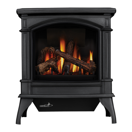
(CDVS600-1 illustrated)
ADD ____ ILLUSTRATED
ADD PRODUCT IMAGE
I T H
O P
T R
T I O
I V E
T
N A
L
FOR INDOOR USE ONLY
NUMBER LABEL HERE
IF SEPARATE MANUALS, ADD "PLACE
ENGLISH
FRENCH PG. 71
W415-1330 / B / 12.06.18
Publicité
Chapitres
Table des Matières
Dépannage

Manuels Connexes pour Continental Fireplaces CDVS600-1N

Sommaire des Matières pour Continental Fireplaces CDVS600-1N
- Page 1 CDVS600-1N / CS600-1N ADD PRODUCT CODE HERE (TRADE GOTHIC LT STD FONT) NATURAL GAS MODELS: ENGLISH CDVS600-1P / CS600-1P PROPANE GAS MODELS: FRENCH PG. 71 INSTALLATION AND ADD MANUAL TITLE OPERATION MANUAL Product Name / Code Gas Stoves Series SAFETY INFORMATION...
-
Page 2: Safety Information
safety information WARNING DANGER • This appliance is hot when operated and can cause severe burns if contacted. • Any changes or alterations to this appliance or its controls can be dangerous and is prohibited. HOT GLASS WILL CAUSE BURNS. •... - Page 3 safety information WARNING • Do not use a blower insert, heat exchanger insert or other accessory not approved for use with this appliance. • This appliance must not be connected to a chimney fl ue pipe serving a separate solid fuel burning appliance.
-
Page 4: Table Des Matières
table of contents general information finishing rating plate information front cast removal dimensions safety barrier installation and removal 36 shipping bracket glass door installation and removal direct venting - model CDVS600-1 battery housing installation typical vent installations glass / door replacement special vent installations log placement 2.2.1 periscope termination... -
Page 5: General Information
Date of Installation: Location of appliance: Installer: Dealer/Distributor contact number: Serial #: Model: Natural Gas: CDVS600-1N Propane: CDVS600-1P CS600-1N CS600-1P 1.0 general information When the appliance is installed at elevations above 4,500ft (1371m), and in the absence of specifi c recommendations from the local authority having jurisdiction, the certifi... - Page 6 general information WARNING • Always light the pilot - whether for the fi rst time or if the gas supply has run out - with the glass door opened or removed. • Provide adequate clearance for servicing and operating the appliance. •...
-
Page 7: Rating Plate Information
GDS60-1N GS60-1N GS60-1P GDS60-1P BAIN ET UN STUDIO. APPROPRIE POUR INSTALLATION DANS UNE MAISON MOBILE SI SON CDVS600-1N CS600-1N CS600-1P CDVS600-1P INSTALLATION CONFORME AUX EXIGENCES DE LA NORME CAN/CSA Z240MH SERIE DE MAISONS MOBILES EQUIPEES AU GAZ, EN VIGUEUR AU CANADA OU AUX ETATS-UNIS DE... -
Page 8: Shipping Bracket
general information shipping bracket WARNING • The top casting is not fastened to the stove assembly. It simply sits on the stove as a lid. For shipping purposes, it is held in place by plastic strapping. Once the strapping is cut, the top should be lifted off carefully and stored in a safe place to avoid damage while completing the installation of the stove. - Page 9 direct venting - model CDVS600-1 2.0 direct venting - model CDVS600-1 WARNING • Risk of fi re. Maintain specifi ed air space clearances to vent pipe and appliance. • The vent system must be supported every 3’(0.9m) for both vertical and horizontal runs. Use support ring assembly W010- 0067 or equivalent non-combustible strapping to maintain the minimum clearance to combustibles for both vertical and horizontal runs.
-
Page 10: Direct Venting - Model Cdvs600
direct venting - model CDVS600-1 Horizontal runs may have a 0” rise per foot or 0mm rise per meter however for optimum performance it is recommended that all horizontal runs have a minimum 1/4” rise per foot or 21mm rise per meter using fl exible venting. For safe and proper operation of the appliance, follow the venting instructions exactly. - Page 11 direct venting - model CDVS600-1 34" (86.4cm) max. 29" (73.7cm) min. 24" (61cm) max. 59 1/2" (151.1cm) min. plus rise* 24" (61cm) min. plus rise* 20 ft. (6m) max. 24” (610mm) min. 12” (305mm) regardless of min. to grade horizontal vent length Max.
-
Page 12: Special Vent Installations
direct venting - model CDVS600-1 special vent installations 2.2.1 periscope termination Use the periscope kit to locate the air termination above grade. The periscope must be installed so that when fi nal grading is completed, the bottom air slot is located a minimum 12” (305mm) above grade. The maximum allowable vent length (including both rise and run) is 10’... -
Page 13: Vent Terminal Clearances
direct venting - model CDVS600-1 vent terminal clearances Covered balcony applications ††* = 3 feet = 2 x ACTUAL (0.9m) (4.6m) note: INSTALLATIONS Wall terminals are for illustration purposes only. Size and shapes may vary. CANADA U.S.A. 12” (30.5cm) 12” (30.5cm) Clearance above grade, veranda porch, deck or balcony. -
Page 14: Venting Application Fl Ow Chart
direct venting - model CDVS600-1 venting application fl ow chart Top Exit Horizontal Termination Vertical Termination Vertical rise is equal Vertical rise is equal Vertical rise is less Vertical rise is less to or greater than the to or greater than the than horizontal run than horizontal run horizontal run... -
Page 15: Defi Nitions
direct venting - model CDVS600-1 defi nitions For the following symbols used in the venting calculations and examples are: > - greater than > - equal to or greater than < - less than < - equal to or less than - total of both horizontal vent lengths (Hr) and offsets (Ho) in feet - combined horizontal vent lengths in feet - offset factor: .03 (total degrees of offset - 90°*) in feet... -
Page 16: Top Exit Horizontal Termination
direct venting - model CDVS600-1 top exit horizontal termination ) > (V See graph to determine the required vertical rise V Simple venting configuration (only one 90° elbow) the required horizontal run H 150 (3810) 12.3 (3.8) (3733.8) REQUIRED 100 (2540) VERTICAL RISE IN 8.3 (2.5) FEET (METERS) V... - Page 17 direct venting - model CDVS600-1 top exit horizontal termination ) ≤ (V See graph to determine the required vertical rise V Simple venting configuration (only one 90° elbow) the required horizontal run H 40 (12.2) 39 (11.9) Required vertical 30 (9.1) rise in feet (meters) V 20 (6.1)
-
Page 18: Rear Exit Horizontal Termination
direct venting - model CDVS600-1 rear exit horizontal termination ) < (V Simple venting configuration See graph to determine the required vertical rise V for the required (only two 90° elbows) horizontal run H 40 (12.2) 40 (12.2) 38.3 (11.7) 38.3 (11.7) 30 (9.1) REQUIRED... - Page 19 direct venting - model CDVS600-1 ) > (V Simple venting configuration See graph to determine the required vertical rise V for the (only two 90° elbows) required horizontal run H 150(3810) 147 (3733.8 12.3 (3.8) REQUIRED VERTICAL RISE IN 100 (2540) 8.3 (2.5) FEET (METERS)V INCHES (MILLIMETERS)
-
Page 20: Top Or Rear Exit Vertical Termination
direct venting - model CDVS600-1 2.10 top or rear exit vertical termination ) < (V See graph to determine the required vertical rise V for the Simple venting configurations. required horizontal run H 40 (12.2) 30 (9.1) REQUIRED VERTICAL RISE IN FEET (METERS)V 20 (6.1) 10 (3.1) - Page 21 direct venting - model CDVS600-1 ) > (V Simple venting configurations. See graph to determine the required vertical rise V for the required horizontal run H 20 (6.1) 19 (5.8) REQUIRED VERTICAL 10 (3.1) RISE IN FEET (METERS)V 3 (0.9) (1.5) (3.1) (4.6)
-
Page 22: Installation Preparation - Model Cdvs600
installation preparation - model CDVS600-1 3.0 installation preparation - model CDVS600-1 orifi ce replacement REAR VENT TERMINATION: Rear exit installations which terminate horizontally and have no verti- cal vent runs must have the BTU input reduced to 21,000 BTU/hr by changing the orifi... -
Page 23: Changing A Top Vent To A Rear Vent
installation preparation - model CDVS600-1 changing a top vent to a rear vent In order to convert the venting confi guration from a top exit to a rear exit, remove components as illustrated. When reinstalling in the alternate position: Check gaskets for tears, replace if necessary to ensure a proper seal. Outer Top Top Heat Shield... -
Page 24: Installation
installation 4.0 installation WARNING • Ensure to unpack all loose materials from inside the fi rebox prior to connecting the gas and electrical supply • If your appliance is supplied with a remote, ensure the remote receiver is in the “OFF” position prior to connecting the gas and electrical supply to the appliance. -
Page 25: Horizontal Installation
installation 4.1.1 horizontal installation WARNING • The fi restop assembly must be installed with the vent shield to the top. • Terminals must not be recessed into a wall or siding more than the depth of the return fl ange of the mounting plate. -
Page 26: Vertical Installation
installation 4.1.2 vertical installation This application occurs when venting through a roof. Installation kits for various roof pitches are available from your authorized dealer / distributor. See the “accessories” section to order specifi c kits required. A. Determine the air terminal location, cut and frame a square opening, as illustrated, in the ceiling and the roof to provide the minimum 1"... -
Page 27: Horizontal Air Terminal Installation - Model Cdvs600
installation 4.1.3 horizontal air terminal installation - model CDVS600-1 WARNING • Terminals must not be recessed into a wall or siding more than the depth of the return fl ange of the mounting plate. Stretch the inner fl ex pipe to the required length taking into account the additional length needed for the fi... -
Page 28: Vertical Air Terminal Installation - Model Cdvs600
installation 4.1.4 vertical air terminal installation - model CDVS600-1 WARNING • Maintain a minimum 2” (51mm) space between the air inlet base and the storm collar. note: Fastening hardware provided with appropriate roof terminal and liner kits. Fasten the roof support to the roof using 6 screws. The roof support is optional. -
Page 29: Appliance Vent Connection - Model Cdvs600
installation appliance vent connection - model CDVS600-1 Attach the adjustable pipe to the last section of rigid pipe. Secure with #8 X 1/2” screws and seal. Self Drilling Screws Install the inner fl ex pipe to the appliance. Secure with a minimum of INSERT three screws and fl... -
Page 30: Vertical Through Existing Chimney
installation vertical through existing chimney WARNING • Risk of fi re. • Co-axial to co-linear venting confi gurations must only be used in a non-combustible chimney or enclosure. Installation in a combustible enclosure could result in a fi re. This appliance is designed to be attached to a 3” (76.2mm) co-linear aluminum fl ex vent system running the full length of a masonry chimney. -
Page 31: Mobile Home Installation - Model Cdvs600
installation mobile home installation - model CDVS600-1 In Canada, mobile home installation may be vented horizontally or vertically. In the United States, it may only be installed vertically. See "vertical venting" or "horizontal air terminal installation" section for installation. For mobile home installations, the appliance must be fastened in place. It is recommended that the appliance be secured in all installations. -
Page 32: Natural Vent Specifi Cs - Model Cs600
installation natural vent specifi cs - model CS600-1 4.7.1 chimney installation WARNING • A chimney venting this appliance shall not vent any solid fuel burning appliance. Three types of chimney systems may be used with this appliance. “B” VENT GAS “A”... -
Page 33: Installing Natural Vent
installation 4.7.2 installing natural vent Follow the instructions of the "B" vent manufacturer for chimney installation. Remove the access plate. Remove and discard the air intake cover plate located directly behind the access plate. Feed the 2 wires, supplied, through the 7" (178mm) collar at the top of the unit, bring them out the air intake opening but behind the rear panel as shown. -
Page 34: Adding Vent Sections
installation 4.7.5 adding vent sections Add chimney sections, according to the manufacturer’s installation instructions. If the chimney system passes through an attic space, a rafter radiation shield or attic insulation shield is required. The chimney must extend at least 3ft (0.9m) above its point of contact with the roof and at least 2ft (0.6m) higher than any wall, roof or building within 10ft (3.1m). -
Page 35: Installing Fl Ashing And Storm Collar
installation 2 FT (0.6m) 10 FT 3 FT (3M) (1m) 7” (178mm) OPTIONAL VENT PIPE 4” (102mm) “B” VENT SECURELY ATTACH VENT ADAPTER TO FLUE COLLAR 4.7.6 installing fl ashing and storm collar The following are generic installation instructions for installing the flashing around a chimney. Installation of all types of factory-built chimney systems is to be in accordance with the chimney manufacturer’s installation instructions. -
Page 36: 5.1 Front Cast Removal
fi nishing 5.0 fi nishing front cast removal Lift the cast top off the unit. Loosen the securing bolts on the cast front (located at either side on the top). Lift up and out. To install the front, repeat in reverse order. safety barrier installation and removal A barrier designed to reduce the risk of burns from the hot viewing glass, is provided with the appliance and shall be installed. -
Page 37: 5.3 Glass Door Installation And Removal
fi nishing glass door installation and removal Care must be taken when removing and installing door to ensure that the gasket at the top of the door does not bunch. When removing the glass door, a simple procedure must be followed in order to not damage the compo- nents. -
Page 38: 5.4 Battery Housing Installation
fi nishing F. Lift glass door up and off edge of fi rebox top and slide it under top retainers to remove. NOTE: When removing the glass door, a simple procedure must be followed in order to not damage the components. G. -
Page 39: 12 5.6 Log Placement
fi nishing log placement Blocked burner ports can cause an incorrect fl ame pattern, carbon deposits and delayed ignition. Phazer logs glow when exposed to direct fl ame and provide a unique and realistic glowing effect. Use only certifi ed phazer logs available from your Continental®... -
Page 40: 12 5.7 Logo Placement
fi nishing logo placement INSERT Remove the backing of the logo supplied and place, as illustrated. IMAGE HERE LOGO switch and bracket installation CONNECT THE TWO WIRES TO THE SWITCH TERMINALS. W415-1330 / B / 12.06.18... -
Page 41: 13 6.0 Optional Blower Installation
6.0 optional blower installation fi nishing Ensure that the access cover plate has been installed. For location, see "SWITCH AND BRACKET INSTALLATION" section. Remove the on/off switch bracket and the cover plate below it. The switch spacers and cover plate may now be discarded. Decide which side of the blower housing you SLOT prefer the on/off switch to be located on. -
Page 42: 14 7.0 Wiring Diagram
fi nishing 7.0 wiring diagram WARNING • Do not wire 110 volts to the valve or wall switch. ACS/IPI SWITCH (OPTIONAL) GREEN ON / OFF ORANGE SWITCH TRANSFORMER IPI / CPI ON / OFF BATTERY HOUSING ELECTRONIC DISCONNECT THESE VALVE CONNECTIONS TO THE ON/OFF SWITCH. -
Page 43: Operating Instructions
operation 8.0 operation WARNING • If you do not follow these instructions exactly, a fi re or explosion may result causing property damage, personal injury or loss of life. • Always light the pilot whether for the fi rst time or if the gas supply has ran out with the glass door opened or removed. -
Page 44: Operation
operation operating instructions - for your safety read before operating OPERATING INSTRUCTIONS / INSTRUCTIONS D’OPÉRATION FOR YOUR SAFETY READ BEFORE OPERATING / POUR VOTRE SÉCURITÉ LIRE AVANT DE FAIRE FONCTIONNER WARNING: ATTENTION: DO NOT TURN ON IF CHILDREN OR OTHER AT RISK INDIVIDUALS ARE NEAR THE APPLIANCE. -
Page 45: Pilot Burner Adjustment
operation 9.0 adjustment pilot burner adjustment Adjust the pilot screw to provide properly sized fl ame. Turn in a clockwise direction to reduce the gas fl ow. Check Pressure Readings: 3/8” - 1/2” Inlet pressure can be checked by turning screw (A) counter- (9.5mm - 12.7mm) clockwise 2 or 3 turns and then placing pressure gauge tubing over the test point. -
Page 46: 23 9.3 Fl Ame Characteristics
operation fl ame characteristics It’s important to periodically perform a visual check of 3/8” - 1/2” (9.5mm - 12.7mm) the pilot and burner flames. Compare them to the ADD IMAGE illustration provided. If any flames appear abnormal, call a service person. Flame must envelop HERE upper... - Page 47 10.0 maintenance operation WARNING • Turn off the gas and electrical power before servicing the appliance. • Appliance may be hot. Do not service until appliance has cooled. • Do not use abrasive cleaners on glass. • Do not paint the pilot assembly. This appliance and its venting system should be inspected before use and at least annually by a qualifi...
-
Page 48: Maintenance
operation 10.2 annual maintenance WARNING • Annual maintenance should be performed by a qualifi ed service technician • The fi rebox becomes very hot during operation. Let the appliance cool completely or wear heat resistant gloves before conducting service. • Never vacuum hot embers. -
Page 49: Replacement Parts
11.0 replacement parts replacement parts WARNING • Failure to position the parts in accordance with this manual or failure to use only parts specifi cally approved with this appliance may result in property damage or personal injury. Contact your dealer for questions concerning prices and policies on replacement parts. Normally, all parts can be ordered through your Authorized dealer / distributor. - Page 50 replacement parts W415-1330 / B / 12.06.18...
- Page 51 replacement parts W415-1330 / B / 12.06.18...
-
Page 52: Accessories
12.0 accessories accessories W415-1330 / B / 12.06.18... - Page 53 13.0 troubleshooting troubleshooting WARNING • Always light the pilot whether for the fi rst time or if the gas supply has run out, with the glass door open or removed. • Turn off gas and electrical power before servicing the appliance. •...
-
Page 54: Troubleshooting
troubleshooting symptom problem test solution Pilot lights Wiring / connection. Inspect all wires, ensure good tight connections. Verify that all wiring is installed exactly as specifi ed. Stops sparking / pilot remains lit but burner will not turn on. Wiring harness. Inspect the wiring harness and verify the harness is tightly connected to the module. -
Page 55: Warranty
14.0 warranty warranty Continental® products are manufactured under the strict standard of the world recognized ISO 9001 : 2015 Quality Management System. Continental® products are designed with superior components and materials assembled by trained craftsmen who take great pride in their work. The burner and valve assembly are leak and test-fi red at a quality test station. The complete appliance is again thoroughly inspected by a qualifi... - Page 56 7200, Route Transcanadienne, Montréal, Québec H4T 1A3 24 Napoleon Road, Barrie, Ontario, Canada L4M 0G8 214 Bayview Drive, Barrie, Ontario, Canada L4N 4Y8 103 Miller Drive, Crittenden, Kentucky, USA 41030 Phone: 1-866-820-8686 continentalfireplaces.com...
- Page 57 CDVS600-1N / CS600-1N ADD PRODUCT CODE HERE (TRADE GOTHIC LT STD FONT) MODÈLES DE GAZ NATUREL CDVS600-1P / CS600-1P MODÈLES DE PROPANE FRANÇAIS FRANÇAIS MANUEL D'INSTALLATION ADD MANUAL TITLE ET D'OPÉRATION Product Name / Code Série des Poêles au Gaz CONSIGNES DE SÉCURITÉ...
-
Page 58: Consignes De Sécurité
consignes de sécurité AVERTISSEMENT • Cet appareil est chaud lorsqu’il AVERTISSEMENT fonctionne et peut causer de graves brûlures en cas de contact. • Toute modifi cation apportée à cet appareil ou aux contrôles peut être LA VITRE CHAUDE CAUSERA dangereux et est interdit. DES BRÛLURES. - Page 59 consignes de sécurité AVERTISSEMENT • N’utilisez pas une souffl erie intégrée, un échangeur de chaleur intégré ni un autre accessoire non approuvé pour cet appareil. • Cet appareil ne doit pas être raccordé au conduit d’une cheminée desservant un autre appareil de chauffage à...
- Page 60 10.2 soins de la vitre modèle CDVS600-1 11.0 pièces de rechange raccordement des évents à l'appareil - 12.0 accessoires modèle CDVS600-1N 13.0 guide de dépannage terminaison verticale à travers une 14.0 garantie cheminée existante installation dans une maison mobile - modèle CDVS600-1...
-
Page 61: Liste De Vérification
Location de l'Appareil: Installateur: Numéro de contact du détaillant / distributeur: # de Série: Modèle: Gaz Naturel: CDVS600-1N Propane: CDVS600-1P CS600-1N CS600-1P 1.0 information générale Lorsque l’appareil est installé à des élévations dépassant 4500 pieds, (1371m) et en l’absence de recommandations spécifi... -
Page 62: Information Générale
information générale WARNING • Always light the pilot - whether for the fi rst time or if the gas supply has run out - with the glass door opened or removed. • Provide adequate clearance for servicing and operating the appliance. •... -
Page 63: Information À Propos De La Plaque D'homologation
GS60-1P GDS60-1P 0-1P BAIN ET UN STUDIO. APPROPRIE POUR INSTALLATION DANS UNE MAISON MOBILE SI SON BAIN ET UN STUDIO IN ET UN STUDIO CDVS600-1N CS600-1N CS600-1P CDVS600-1P VS600-1P INSTALLATION CONFORME AUX EXIGENCES DE LA NORME CAN/CSA Z240MH SERIE DE... -
Page 64: Support De Transport
information générale support de transport AVERTISSEMENT • Le dessus du poêle n'est pas fi xé à l'appareil. Il repose sur l'appareil, tel un couvercle. À des fi ns de transport, il est maintenu en place à l'aide de courroies de plastique. Une fois les courroies coupées, le dessus du poêe doit être soulevé... - Page 65 évacuation - modèle CDVS600-1 2.0 évacuation - modèle CDVS600-1 AVERTISSEMENT • Risque d’incendie. Conservez les dégagements nécessaires au conduit d’évent et à l’appareil. • Les courses horizontales et verticales du système doivent être supportées à tous les 3 pi (0,9m). Utilisez l’ensemble de support mural Wolf Steel W010-0067 ou des attaches incombustibles équivalents afi...
-
Page 66: Évacuation - Modèle Cdvs600
évacuation - modèle CDVS600-1 La prise d’air de la terminaison extérieure doit demeurer dégagée en tout temps. Vérifi ez la prise d’air de la terminaison au moins une fois l’an pour vous assurer qu’elle n’est pas obstruée ni endommagée. Ne combinez pas de composants rigides ou fl exibles ni de composants d’évacuation provenant de fabricants différents. -
Page 67: Installations Typiques D'évents
évacuation - modèle CDVS600-1 installations typiques d'évents 16" (40,6cm) min. 16" (40,6cm) min. 40 pieds (12m) 40 pieds (12m) max. max. 34" (86,4cm) 34" (86,4cm) min. min. 30 1/2" (77,5cm) 24" (61cm) ÉVACUATION SUR ÉVACUATION À LE DESSUS L'ARRIÈRE W415-1330 / B / 12.05.18... - Page 68 évacuation - modèle CDVS600-1 34" (86,4cm) max. 24" (61cm) 29" (73,7cm) max. min. 59 1/2" (151,1cm) min. plus l'élévation* 24" (61cm) min. plus l'élévation* 20" (508mm) 24" (610mm) MINIMUM 12" (305mm) INDÉPENDAMMENT DE MINIMUM AU LA LONGUEUR D’ÉVENT NIVEAU DU HORIZONTAL COURSE HORIZONTALE MAXIMALE...
-
Page 69: Installations Particulières D'évents
évacuation - modèle CDVS600-1 installations particulières d'évents 2.2.1 ensemble périscopique Utilisez l’ensemble périscopique afi n de positionner la terminaison au-dessus du niveau du sol. L’ensemble périscopique doit être installé de façon à ce que la fente d’air du bas soit située à un minimum de 12 pouces (305mm) au-dessus du niveau du sol. -
Page 70: Dégagements De La Terminaison
évacuation - modèle CDVS600-1 dégagements de la terminaison Applications pour balcon couvert ††* = 3 feet = 2 x ACTUAL (0.9m) (4.6m) note: INSTALLATIONS Les terminaux du mur sont à des fi ns d’illustration seulement. La taille et les formes peuvent varier. CANADA É.-U. -
Page 71: Charte D'application Des Évacuations
évacuation - modèle CDVS600-1 charte d'application des évacuations Évacuation sur le dessus Terminaison horizontale Terminaison verticale La course verticale est La course verticale La course verticale La course verticale plus grande ou égale à est plus petite que la est plus grande ou est plus petite que la la course horizontale course horizontale... -
Page 72: Légende
évacuation - modèle CDVS600-1 légende Les symboles suivants sont utilisés dans le calcul et les exemples d’évacuation : > - plus grand que > - plus grand ou égal à < - plus petit que < - plus petit ou égal à - total de la longueur des courses horizontales (H ) plus la valeur des déviations (H ) en pieds... -
Page 73: Évacuation Sur Le Dessus/Terminaison Horizontale
évacuation - modèle CDVS600-1 évacuation sur le dessus/terminaison horizontale ) > (V Consultez le graphique pour déterminer la course verticale Configuration d'évacuation simple (un coude nécessaire V par rapport à la course horizontale requise H de 90° seulement). 150 (3810) 12,3 (3,8) (3733.8) COURSE... -
Page 74: Évacuation Sur Le Dessus / Terminaison Horizontale
évacuation - modèle CDVS600-1 évacuation sur le dessus / terminaison horizontale ) ≤ (V Configuration d’évacuation simple (un coude de 90° Consultez le graphique pour déterminer la course seulement) verticale nécessaire V par rapport à la course horizontale requise H 40 (12,2) 39 (11,9) Course verticale... -
Page 75: Évacuation À L'arrière / Terminaison Horizontale
évacuation - modèle CDVS600-1 évacuation à l'arrière / terminaison horizontale ) < (V Configuration d'évacuation simple See graph to determine the required vertical rise V for the required (deux coudes de 90° seulement) horizontal run H 40 (12.2) 40 (12,2) 38.3 (11.7) 38,3 (11,7) COURSE... - Page 76 évacuation - modèle CDVS600-1 ) > (V Consultez le graphique pour déterminer la course verticale Configuration d'évacuation simple nécessaire V par rapport à la course horizontale requise H (deux coudes de 90° seulement) 150(3810) 12,3 (3,8) 147 (3733.8 COURSE 100 (2540) 8,3 (2,5) VERTICALE REQUISE...
-
Page 77: Évacuation Sur Le Dessus Ou À L'arrière / Terminaison Verticale
évacuation - modèle CDVS600-1 2.10 évacuation sur le dessus ou à l'arrière / terminaison verticale ) < (V Consultez le graphique pour déterminer la course verticale Configurations d'évacuation simples. nécessaire V par rapport à la course horizontale requise H 40 (12,2) 30 (9,1) COURSE VERTICALE... - Page 78 évacuation - modèle CDVS600-1 ) > (V Configurations d'évacuation simples. Consultez le graphique pour déterminer la course verticale nécessaire V par rapport à la course horizontale requise H 20 (6,1) 19 (5,8) COURSE VERTICALE 10 (3,1) REQUISE EN PIEDS 3 (0,9) (MÈTRES) V (1,5) (3,1)
-
Page 79: Préparatifs Pour L'installation - Modèle Cdvs600
3.0 préparatifs pour l'installation - modèle CDVS600-1 préparatifs pour l'installation - modèle CDVS600-1 remplacement de l'injecteur du brûleur TERMINAISON POUR UNE ÉVACUATION À L'ARRIÈRE : Pour les installations à évacuation arrière qui se terminent horizontale- ment et ne comportent pas de conduits d'évents verticaux, le débit minimal doit être réduite à... -
Page 80: Modifi Cation D'évacuation Sur Le Dessus À Évacuation À L'arrière
préparatifs pour l'installation - modèle CDVS600-1 modifi cation d'évacuation sur le dessus à évacuation à l'arrière Afi n de convertir le système d'évent à évacuation sur le dessus en évacuation à l'arrière, retirez les composants tel qu'illustré: Lors de la réinstallation à la position alternative : inspectez les joints d’étanchéité pour des déchirures, remplacez-les si nécessaire pour assurer une bonne étanchéité. -
Page 81: Dégagements Minimaux Aux Matériaux Combustibles
installation 4.0 installation AVERTISSEMENT • Avant d’effectuer les branchements pour l’alimentation en gaz et électronique, assurez-vous de retirer toute composante non fi xée à l’intérieur de la chambre de combustion. • Si votre appareil comprend un système de télécommande, assurez-vous que le récepteur est à la position «... -
Page 82: Installation Horizontale
installation 4.1.1 installation horizontale AVERTISSEMENT • L’espaceur coupe-feu doit être installé avec l’écran protecteur orienté vers le haut. • La terminaison ne doit pas être enchâssée dans le mur ou le revêtement extérieur plus que l’épaisseur de la bride de la plaque de montage. PROTECTEUR Cette confi... -
Page 83: Installation Verticale
installation 4.1.2 installation verticale Cette confi guration s’applique lorsque l’évacuation se fait à travers un toit. Des ensembles d’installation pour les différentes pentes de toit sont disponibles chez votre détaillant autorisé. Voir la section « accessoires » dans le manuel du propriétairepour commander l’ensemble spécifi que dont vous avez besoin. -
Page 84: Installation De La Terminaison
installation 4.1.3 installation de la terminaison horizontale - modèle CDVS600-1 AVERTISSEMENT • La terminaison ne doit pas être enchâssée dans un mur ou un revêtement extérieur à une profondeur excédant celle de la bride de la plaque de montage. Étirez la gaine fl exible intérieure à la longueur requise en tenant compte de la longueur additionnelle nécessaire ADD FASTENER TYPE pour la surface du mur fi... -
Page 85: Installation Dela Terminaison Verticale
installation 4.1.4 installation dela terminaison verticale - modèle CDVS600-1 AVERTISSEMENT • Conservez un espace minimale de 2 po (51mm) entre la base de la prise d’air et le collet de solin. Matériel de fi xation fourni avec les ensembles de terminal pour toit et raccord appropriées. Fixez le support de toit au toit à... -
Page 86: Raccordement Des Évents À L'appareil - Modèle Cdvs600-1N
évents à l'appareil - modèle CDVS600-1N Attachez le tuyau télescopique à la dernière section de conduit rigide. Fixez-le avec des vis et scellez. #8 X 1/2” Fixez-la à l’aide d’au moins trois vis et rondelles lorsque vous... -
Page 87: Terminaison Verticale À Travers Une Cheminée Existante
installation terminaison verticale à travers une cheminée existante AVERTISSEMENT • Risque d’incendie • Les confi gurations d’évacuation coaxiales à colinéaires ne doivent être utilisées que dans une cheminée ou une enceinte de nature incombustible. Une installation dans une enceinte combustible peut causer un incendie. Cet appareil est conçu pour être raccordé... -
Page 88: Installation Dans Une Maison Mobile - Modèle Cdvs600
installation installation dans une maison mobile - modèle CDVS600-1 Au Canada, l'installation de l'évacuation dans une maison mobile peut être horizontale ou verticale. Aux États- Unis, l'évacuation ne peut être que verticale. Voir les sections « ÉVACUATION VERTICALE » ou « INSTALLATION DE LA TERMINAISON HORIZONTALE » pour l'installation. Pour une installation dans une maison mobile, l'appareil doit être fi... - Page 89 installation spécifi cation pour le tirage naturel - modèle CS600-1 4.7.1 installation de la cheminée AVERTISSEMENT • Une cheminée servant d’évacuation à cet appareil ne doit pas servir pour un appareil de chauffage à combustible solide. Trois types de systèmes de cheminée peuvent être utilisés avec cet appareil. ÉVENT DE TYPE ÉVENT DE TYPE «...
-
Page 90: Air Comburant
installation 4.7.2 installation de l'évent de type « B » Suivez les instructions du fabricant d'évent de type « B » pour l'installation de la cheminée. Enlevez la plaque d'accès. Retirez et jetez le couvercle de la prise d'air situé directement en arrière de la plaque d'accès. - Page 91 installation 4.7.5 ajout de sections d'évents Ajoutez des sections de cheminée, selon les instructions d’installation du fabricant. Si la cheminée devra dépasser par l’espace grenier un écran protecteur de chevrons ou une bouclier d'isolation du grenier est requis. La cheminée doit dépasser le toit d’au moins 3’...
-
Page 92: Optionnel
installation 2' (0,6m) 3' (0,9m) (3m) TUYAU OPTIONNEL DE 7" (178mm) ÉVENT DE TYPE « B » DE 4” (102mm) FIXEZ SOLIDEMENT L’ADAPTATEUR AU COLLET DE LA BUSE DE L’APPAREIL 4.7.6 installation du solin et du collet de solin Les instructions d’installation suivants sont générales pour l’installation du solin autours de la cheminée. L’Installation de tous les types de systèmes construits en usine doivent être installées en confomé... - Page 93 fi nition 5.0 fi nition enlèvement de la façade en fonte Soulevez et retirez le dessus de l'appareil. Dévissez les boulons de fi xation de la façade en fonte (situés de chaque côté dans le haut). Soulevez et retirez. Pour installer la façade, répétez la procédure en sens inverse. installation et enlèvement de la barrière de protection Une barrière conçu à...
-
Page 94: Finition
fi nition enlèvement et installation de la porte vitrée Lorsque vous installez la porte vitrée, de simples instructions doivent être suivies afi n de ne pas l'endommager. Soulevez et retirez le dessus de l'appareil. Soulevez la façade de l'appareil hors de ses ancrages (situés de chaque côté dans le haut). Ouvrez la porte de contrôle de la soupape. - Page 95 fi nition dispositon des bûches Le blocage des orifi ces du brûleur peut créer une fl amme irrégulière, des dépôts de carbone et un retard d'allumage. Les bûches Phazer rougeoient lorsqu'elles sont exposées à une fl amme directe, créant un effet incandescent réaliste et unique.
-
Page 96: Mise En Place Du Logo
fi nition mise en place du logo Retirez le papier dorsal du logo fourni et positionnez-le de façon à camoufl er les trous. LOGO installation de l'interrupteur et du support RELIEZ LES DEUX FILS AUX BORNES DE L’INTERRUPTEUR W415-1330 / B / 12.06.18... -
Page 97: Installation De La Souffl Erie
6.0 installation de la souffl erie fi nition Assurez-vous que la plaque d'accès a été installée. Voir la section « INSTALLATION DE L'INTERRUPTEUR ET DU SUPPORT ». Retirez le support de l'interrupteur marche/ arrêt et la plaque en dessous de celui-ci. Les espaceurs de l'interrupteur et la plaque peuvent être jetés. -
Page 98: Schéma De Câblage
schéma de câblage 7.0 schéma de câblage AVERTISSEMENT • Ne raccordez pas l’interrupteur mural ou la soupape de gaz à l’alimentation électrique (110 volts). INTERRUPTEUR ACS/IPI (OPTIONNEL) INTERRUPTEUR VERT ORANGE MARCHE/ARRÊT TRANSFORMATEUR IPI / CPI ON / OFF BOÎTIER DÉBRANCHEZ CES DE PILES RACCORDS DE L’INTERRUP- SOUPAPE... - Page 99 fonctionnement 8.0 fonctionnement AVERTISSEMENT • Si ces instructions ne sont pas suivies à la lettre, un incendie ou une explosion pourraient s'ensuivre, causant des dommages matériels, des blessures corporelles ou des pertes de vie. • Allumez toujours la veilleuse, que ce soit pour la première fois ou lorsque l'approvisionnement en gaz est épuisé, avec la porte vitrée ouverte ou retirée.
-
Page 100: Fonctionnement
fonctionnement instructions de fonctionnement - pour votre sécurité, lisez ce qui suit avant d'allumer l'appareil OPERATING INSTRUCTIONS / INSTRUCTIONS D’OPÉRATION FOR YOUR SAFETY READ BEFORE OPERATING / POUR VOTRE SÉCURITÉ LIRE AVANT DE FAIRE FONCTIONNER WARNING: ATTENTION: DO NOT TURN ON IF CHILDREN OR OTHER AT RISK INDIVIDUALS ARE NEAR THE APPLIANCE. - Page 101 réglages 9.0 réglages réglage de la veilleuse Ajustez la vis de la veilleuse pour obtenir une fl amme de taille normale. Tournez vers la droite pour réduire l’apport de gaz. 3/8” - 1/2” Vérifi ez la pression: (9.5mm - 12.7mm) Pour vérifi...
- Page 102 réglages caractéristiques de la fl amme 3/8” - 1/2” Il est important d’effectuer périodiquement une (9.5mm - 12.7mm) inspection visuelle de la flamme de la veilleuse et du ADD IMAGE brûleur. Comparez-les à ces illustrations. Si des flammes paraissent anormales, contactez un HERE La flamme doit envelopper technicien de service.
- Page 103 entretien 10.0 entretien AVERTISSEMENT • Coupez l’alimentation en gaz et l’alimentation électrique avant de procéder à l’entretien de l’appareil. • L’appareil peut être chaud. Attendez qu’il soit refroidi avant d’en faire l’entretien. • N’utilisez pas de produits abrasifs. • Ne peinture pas l’assemblage de la veilleuse. Cet appareil et son système d’évacuation devraient être inspectés avant la première utilisation et au moins une fois l’an par un technicien de service qualifi...
-
Page 104: Entretien Annuel
entretien 10.1 entretien annuel AVERTISSEMENT • Le caisson devient trés chaud lors du fonctionnement. Laissez l’appareil se refroidir complétement ou portez des gants antichaleur avant d’effectuer l’entretien. • Ne jamais aspirer des braises qui sont chaudes. • Ne peinturez pas l’assemblage de la veilleuse. •... - Page 105 pièces de rechange 11.0 pièces de rechange AVERTISSEMENT • Omettre de positionner les pièces conformément à ce manuel ou d’utiliser uniquement des pièces spécifi quement approuvées pour cet appareil peut causer des dommages matériels ou des blessures corporelles. Contactez votre détaillant pour les questions concernant les prix et la disponibilité des pièces de remplace- ment.
-
Page 106: Pièces De Rechange
pièces de rechange W415-1330 / B / 12.06.18... - Page 107 pièces de rechange W415-1330 / B / 12.05.18...
- Page 108 12.0 accessoires pièces de rechange W415-1330 / B / 12.06.18...
- Page 109 guide de dépannage 13.0 guide de dépannage AVERTISSEMENT • Allumez toujours la veilleuse, que ce soit pour la première fois ou lorsque l’approvisionnement en gaz est épuisé, avec la porte vitrée ouverte ou retirée. • Coupez l’alimentation en gaz et l’alimentation électrique avant de procéder à l’entretien de l’appareil. •...
-
Page 110: Guide De Dépannage
guide de dépannage symptôme problème solution Continue de produire Court circuit du connexion Vérifi ez toutes les connexions. Vérifi ez les connexions de des étincelles et la desserrée dans la tige de la l'assemblage de la veilleuse sont serrées, vérifi ez aussi si ces veilleuse s'allume, mais sonde. -
Page 111: Garantie
14.0 garantie guide de dépannage Les produits CONTINENTAL® sont fabriqués conformément aux normes strictes du Système de Gestion de la Qualité mondialement reconnu ISO 9001 : 2015. Les produits CONTINENTAL® sont conçus avec des composants et des matériaux de qualité supérieure, assemblés par des artisans qualifi... - Page 112 7200, Route Transcanadienne, Montréal, Québec H4T 1A3 24 Napoleon Road, Barrie, Ontario, Canada L4M 0G8 214 Bayview Drive, Barrie, Ontario, Canada L4N 4Y8 103 Miller Drive, Crittenden, Kentucky, USA 41030 Phone: 1-866-820-8686 continentalfireplaces.com...