Table des Matières

Manuels Connexes pour FS UMC-GA1F1T


Sommaire des Matières pour FS UMC-GA1F1T
- Page 1 UNMANAGED ETHERNET MEDIA CONVERTERS UNMANAGED ETHERNET MEDIENKONVERTER CONVERTISSEURS DE MÉDIA ETHERNET NON GÉRÉS Quick Start Guide V3.0 Quick-Start Anleitung Guide de Démarrage Rapide...
- Page 2 Introduction Thank you for choosing FS Mini Unmanaged Ethernet Media Converters. This guide is designed to familiarize you with the layout of the media converters and describes how to deploy them in your network. UMC-GA1F1T UMC-GA1F2T - 1 -...
- Page 3 UMC-GA1SC1T-MM UMC-GA1SC1T-SM PW R2 PW R1 FA N 2 FA N 1 O F F IN P U T : A C 1 0 0 -2 4 0 V 5 0 /6 0 H z PW R2 F U S E : 3 FA N .1 5 A PW R1...
-
Page 4: Accessories
Accessories UMC-GA1F1T/UMC-GA1F2T/ UMC-GA1SC1T-MM/UMC-GA1SC1T-SM: Power Adapter x1 MFMC-12DP: Power Cords x2 M4 Screws x N Mounting Bracket x12 NOTE: The power adapter will be packed according to the plug standard of di erent regions. This picture is for reference only. Please refer to the product received. -
Page 5: Hardware Overview
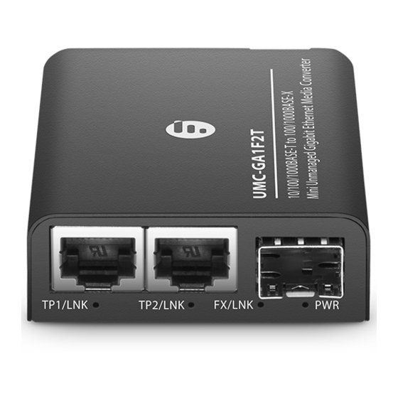
Hardware Overview Front Panel Ports UMC-GA1F1T TP/LNK 1000M FX/LNK RJ45 Port SFP Port UMC-GA1F2T TP1/LNK TP2/LNK FX/LNK RJ45 Port RJ45 Port SFP Port Ports Description RJ45 10/100/1000Base-T RJ45 port for Ethernet connection Hot swappable SFP port for 1G ber connection... - Page 6 UMC-GA1SC1T-MM/UMC-GA1SC1T-SM TP/LNK FX/LNK RJ45 Port SC Port SC Port Ports Description RJ45 10/100/1000Base-T RJ45 port for Ethernet connection SC port for duplex SC single mode or multimode ber connection - 5 -...
- Page 7 Panel LEDs Model: UMC-GA1F1T TP/LNK 1000M FX/LNK TP/LNK 1000M FX/LNK PWR Status Description Link through copper port is successfully Green established, but no data transmission. Blinking Copper port is actively sending or TP/LNK Green receiving data. Copper port is linked down.
- Page 8 Model: UMC-GA1F2T TP1/LNK TP2/LNK FX/LNK TP1/LNK TP2/LNK FX/LNK PWR Status Description Green TP1 port is operating at 1000Mbps. TP1/LNK TP1 port is operating at 100Mbps. Dual Color TP1 port is operating at 10Mbps. Green TP2 port is operating at 1000Mbps. TP2/LNK TP2 port is operating at 100Mbps.
- Page 9 Model: UMC-GA1SC1T-MM/UMC-GA1SC1T-SM TP/LNK FX/LNK TP/LNK FX/LNK PWR Status Description The link through TP port is successfully Green established. Blinking The TP port is actively sending or TP/LNK Green receiving data. The TP port link is down. Green The TP port is operating at 1000Mbps. The TP port is operating at 10/100Mbps.
-
Page 10: Rear Panel
Description PWR1/PWR2 Green The device is powered on. FAN1/FAN2 Green The fan is working properly. Rear Panel Model: UMC-GA1F1T/UMC-GA1F2T/UMC-GA1SC1T-MM/ UMC-GA1SC1T-SM 5-12V Model: MFMC-12DP Dual AC Redundancy Power Supplies INPUT : AC 100-240V 50/60Hz INPUT : AC 100-240V 50/60Hz PWR2 PWR1... - Page 11 Bottom Panel (DIP Switch) Model: UMC-GA1F1T Function Status Description Disable LFP Function Enable Disable ALS Function (Only for SFP) Enable Disable FX Reset Enable FX 1000M FX Speed Set FX 100M/1000M NOTE: LFP (Link Fault Pass Through) Function: If enabled,...
- Page 12 Model: UMC-GA1F2T Function Status Description Reserved Normal (Up to Jumbo 1500Bytes) Frame Up to 9KB Disable Port Isolation Enable FX 1000M FX Speed Set FX 100M NOTE: If enabled, Layer 2 network tra c will not be forwarded between the two RJ45 ports in the same VLAN. - 11 -...
- Page 13 Model: UMC-GA1SC1T-MM/UMC-GA1SC1T-SM Function Status Description Disable LFP Function Enable Disable ALS Function (Only for SFP) Enable Disable FX Reset Enable FX 1000M FX Speed Set FX 100M/1000M NOTE: LFP (Link Fault Pass Through) Function: If enabled, when a device is connected to the converter and the TP/ ber line loses the link, the converter's ber will disconnect the link of transmit.
- Page 14 Site Environment UMC-GA1F1T/UMC-GA1F2T Do not operate it in an area that exceeds an ambient temperature of 40°C. The installation site should be well ventilated. Be sure that the Media Converter is level and stable to avoid any hazardous conditions. Do note install the equipment in a dusty environment.
-
Page 15: Desk Mounting
Installing Desk Mounting Place the media converters on a at, secure surface (such as a desk), leaving ample space around them for ventilation. - 14 -... - Page 16 Rack Mounting (Used with MFMC-12DP 12 Slots Mini Media Converter Chassis) 1. Install the hanging ears on the left rear side of the media converters with two screws. PW R FX /L NK 10 00 M TP /L NK 2. Install the media converters in the chassis in sequence (First install the lower level, then the upper level).
- Page 17 3. Place the chassis into the rack. Align the brackets to the side holes on the rack and use the rack screws to secure the chassis to the rack. Connecting to the Power - 16 -...
- Page 18 1. Desk Mounting: Connect the power adapters to the media c onverters and verify that the Power LED lights up. 0 / 6 0 H Z - 2 4 0 V 5 A C 1 0 0 I N P U T : F U S E :3 .1 F A N O F F...
- Page 19 Connecting to the RJ45 Port 1. Connect an Ethernet cable to the RJ45 port of the media converter. S 3 9 0 0 - 2 4 T 4 S 2. Connect the other end of the Ethernet cable to the network device (switch, PC, router, etc.).
- Page 20 Connecting to the SFP Port 1. Insert an SFP module into the SFP slot. 2. Connect a ber optic cable to the SFP module. Plug the other end of the ber optic cable to the ber network. NOTE: Both multimode and single mode cablings are supported.
- Page 21 Connecting to the SC Port 1. Connect a ber optic cable to the SC port. Plug the other end of the ber optic cable to the ber network. TX and RX must be paired at both ends. NOTE: The media converter is installed with SC port transceiver as default.
- Page 22 Troubleshooting The per port LED is not lit Check the cable connection of the Media Converter. Performance is bad Check the speed duplex mode of the partner device. The Media Converter usually runs in auto-negotiation mode. If the partner is set to half duplex, the performance will be poor.
-
Page 23: Product Warranty
Contact Us Product Warranty FS ensures our customers that any damage or faulty items due to our workmanship, we will o er a free return within 30 Days from the day you receive your goods. This excludes any custom made items or tailored solutions. - Page 24 Einführung Vielen Dank, dass Sie sich für FS Mini Unmanaged Ethernet Medienkonverter entschieden haben. Diese Anleitung soll Sie mit dem Aufbau der Medienkonverter vertraut machen und beschreibt, wie Sie diese in Ihrem Netzwerk einsetzen. UMC-GA1F1T UMC-GA1F2T - 23 -...
- Page 25 UMC-GA1SC1T-MM UMC-GA1SC1T-SM PW R2 PW R1 FA N 2 FA N 1 O F F IN P U T : A C 1 0 0 -2 4 0 V 5 0 /6 0 H z PW R2 F U S E : 3 FA N .1 5 A FA N 2...
- Page 26 Zubehör UMC-GA1F1T/UMC-GA1F2T/ UMC-GA1SC1T-MM/UMC-GA1SC1T-SM: Netzadapter x1 MFMC-12DP: Netzkabel x2 M4-Schraube x N Montagehalterung x12 HINWEIS: Der Netzadapter wird entsprechend dem Steckerstandard der verschiedenen Regionen verpackt. Dieses Bild dient nur als Referenz. Bitte beziehen Sie sich auf das erhaltene Produkt. - 25 -...
-
Page 27: Beschreibung
Übersicht Ports an der Vorderseite UMC-GA1F1T TP/LNK 1000M FX/LNK RJ45 Port SFP Port UMC-GA1F2T TP1/LNK TP2/LNK FX/LNK RJ45 Port RJ45 Port SFP Port Ports Beschreibung RJ45 10/100/1000Base-T RJ45-Port für Ethernet-Anschluss Hot-Swap-fähiger SFP-Port für 1G-Glasfaseranschluss - 26 -... - Page 28 UMC-GA1SC1T-MM/UMC-GA1SC1T-SM TP/LNK FX/LNK RJ45 Port SC Port SC Port Ports Beschreibung RJ45 10/100/1000Base-T RJ45-Port für Ethernet-Anschluss SC-Port für Duplex-SC-Singlemode- oder Multimode-Glasfaser-Anschluss - 27 -...
- Page 29 Panel LEDs Modell: UMC-GA1F1T TP/LNK 1000M FX/LNK TP/LNK 1000M FX/LNK PWR Status Beschreibung Verbindung über Kupferanschluss Grün erfolgreich aufgebaut, aber keine Datenübertragung. TP/LNK Blinkend Der Kupferanschluss sendet oder Grün empfängt aktiv Daten. Der Kupferport ist nicht verbunden. Grün Der Kupferport arbeitet mit 1000Mbps.
- Page 30 Modell: UMC-GA1F2T TP2/LNK FX/LNK TP1/LNK TP1/LNK TP2/LNK FX/LNK PWR Status Beschreibung Grün Der TP1-Port arbeitet mit 1000Mbps. TP1/LNK Der TP1-Port arbeitet mit 100Mbps. Zweifarbig Der TP1-Port arbeitet mit 10Mbps. Grün Der TP2-Port arbeitet mit 1000Mbps. TP2/LNK Der TP2-Port arbeitet mit 100Mbps. Zweifarbig Der TP2-Port arbeitet mit 10Mbps.
- Page 31 Modell: UMC-GA1SC1T-MM/UMC-GA1SC1T-SM TP/LNK FX/LNK TP/LNK FX/LNK PWR Status Beschreibung Die Verbindung über den TP-Port ist Grün erfolgreich hergestellt. Der TP-Port sendet oder empfängt TP/LNK Blinkt grün aktiv Daten. Der TP-Port ist down gelinkt. Grün Der TP-Port arbeitet mit 1000Mbps. Der TP-Port arbeitet mit 10/100Mbps. Die Verbindung über den Faserport Grün ist erfolgreich hergestellt.
- Page 32 FUSE : 3.15A Status Beschreibung PWR1/PWR2 Grün Das Gerät ist eingeschaltet. FAN1/FAN2 Grün Das Gerät ist eingeschaltet. Rückseite Modell: UMC-GA1F1T/UMC-GA1F2T/UMC-GA1SC1T-MM/ UMC-GA1SC1T-SM 5-12V Modell: MFMC-12DP Zwei AC-Redundanz-Stromversorgungen INPUT : AC 100-240V 50/60Hz INPUT : AC 100-240V 50/60Hz PWR2 PWR1 PWR2 PWR1...
- Page 33 Bodenplatte (DIP-Schalter) Modell: UMC-GA1F1T Funktion Status Beschreibung Ausschalten LFP Function Einschalten Ausschalten ALS Function (Only for SFP) Einschalten Ausschalten FX Reset Einschalten FX 1000M FX Speed Set FX 100M/1000M HINWEIS: LFP (Link Fault Pass Through) Funktion: Wenn diese Funktion aktiviert ist, trennt die Faser des Konverters die Verbindung, wenn ein Gerät an den Konverter angeschlossen...
- Page 34 Modell: UMC-GA1F2T Funktion Status Beschreibung Reserved Normal (Bis zu Jumbo Frame 1500Bytes) Bis zu 9KB Ausschalten Port Isolation Einschalten FX 1000M FX Speed Set FX 100M HINWEIS: Wenn diese Option aktiviert ist, wird der Layer-2-Netzwerkverkehr nicht zwischen den beiden RJ45-Ports im selben VLAN weitergeleitet. - 33 -...
- Page 35 Modell: UMC-GA1SC1T-MM/UMC-GA1SC1T-SM Funktion Status Beschreibung Deaktiviert LFP-Funktion Aktiviert Deaktiviert ALS-Funktion (nur bei SFP) Aktiviert Deaktiviert FX Reset Aktiviert FX 1000M FX Speed Set FX 100M/1000M HINWEIS: LFP (Link Fault Pass Through) Funktion: Wenn diese Funktion aktiviert ist, trennt die Faser des Konverters die Verbindung, wenn ein Gerät an den Konverter angeschlossen ist und die TP/Faser-Leitung die Verbindung verliert.
- Page 36 Standortumgebung UMC-GA1F1T/UMC-GA1F2T Betreiben Sie das Gerät nicht in einem Bereich, der eine Umgebungstemperatur von 40°C überschreitet. Der Aufstellungsort sollte gut belüftet sein. Achten Sie darauf, dass der Medienkonverter eben und stabil steht, um gefährliche Bedingungen zu vermeiden. Installieren Sie das Gerät nicht in einer staubigen Umgebung.
-
Page 37: Montage Auf Einem Tisch
Installation Montage auf einem Tisch Stellen Sie die Medienkonverter auf eine ebene, sichere Ober äche (z. B. einen Schreibtisch) und lassen Sie um sie herum ausreichend Platz für die Belüftung. - 36 -... - Page 38 Rack-Montage (verwendet mit MFMC-12DP 12-Slot-Mini-Medienkonverter-Gehäuse) 1. Montieren Sie die Aufhängeösen an der linken Rückseite des Medienkonverters mit zwei Schrauben. PW R FX /L NK 10 00 M TP /L NK 2. Bauen Sie die Medienkonverter der Reihe nach in das Gehäuse ein (zuerst die untere Ebene, dann die obere Ebene).
-
Page 39: Anschluss An Das Stromnetz
3. Setzen Sie das Gehäuse in das Rack ein. Richten Sie die Halterungen an den seitlichen Löchern des Racks aus und verwenden Sie die Rack-Schrauben, um das Gehäuse im Rack zu befestigen. Anschluss an das Stromnetz - 38 -... - Page 40 1. Montage auf einem Tisch: Schließen Sie die Stromadapter an die Medienkonverter an und prüfen Sie, ob die Power-LED leuchtet. 0 / 6 0 H Z - 2 4 0 V 5 A C 1 0 0 I N P U T : F U S E :3 .1 F A N O F F...
- Page 41 Anschluss an den RJ45-Port 1. Schließen Sie ein Ethernet-Kabel an den RJ45-Anschluss des Medienkonverters an. S 3 9 0 0 - 2 4 T 4 S 2. Schließen Sie das andere Ende des Ethernet-Kabels an das Netzwerkgerät (Switch, PC, Router usw. ) an. - 40 -...
- Page 42 Anschluss an den SFP-Port 1. Stecken Sie ein SFP-Modul in den SFP-Steckplatz. 2. Schließen Sie ein Glasfaserkabel an das SFP-Modul an. Schließen Sie das andere Ende des Glasfaserkabels an das Glasfasernetzwerk an. HINWEIS: Es werden sowohl Multimode- als auch Singlemode-Verkabelungen unterstützt. Stellen Sie sicher, dass beide Seiten des SFP-Moduls den gleichen Medientyp aufweisen.
- Page 43 Anschluss an den SC-Port 1. Schließen Sie ein Glasfaserkabel an den SC-Port an. Schließen Sie das andere Ende des Glasfaserkabels an das Glasfasernetzwerk an. TX und RX müssen an beiden Enden gepaart sein. HINWEIS: Der Medienkonverter ist standardmäßig mit einem SC-Port-Transceiver installiert. - 42 -...
- Page 44 Fehlerbehebung Die LED des jeweiligen Ports leuchtet nicht Überprüfen Sie den Kabelanschluss des Medienkonverters. Die Leistung ist schlecht Überprüfen Sie den Geschwindigkeits-Duplex-Modus des Partnergeräts. Der Medienkonverter läuft normalerweise im Autonegotiationsmodus. Wenn der Partner auf Halbduplex eingestellt ist, ist die Leistung schlecht.
- Page 45 Kontakt Produktgarantie FS sichert seinen Kunden zu, dass wir bei Schäden oder fehlerhaften Artikeln, die auf unsere Verarbeitung zurückzuführen sind, eine kostenlose Rücksendung innerhalb von 30 Tagen ab dem Tag des Erhalts der Ware anbieten. Dies gilt nicht für Sonderanfertigungen oder maßgeschneiderte Lösungen.
- Page 46 Introduction Merci d'avoir choisi les mini convertisseurs de média Ethernet non gérés de FS. Ce guide est conçu pour que vous puissiez vous familiariser avec la con guration des convertisseurs de médias et indique comment procéder avec son déploiement. UMC-GA1F1T...
- Page 47 UMC-GA1SC1T-MM UMC-GA1SC1T-SM PW R2 PW R1 FA N 2 FA N 1 O F F IN P U T : A C 1 0 0 -2 4 0 V 5 0 /6 0 H z PW R2 F U S E : 3 FA N .1 5 A FA N 2...
-
Page 48: Accessoires
Accessoires UMC-GA1F1T/UMC-GA1F2T/ UMC-GA1SC1T-MM/UMC-GA1SC1T-SM: Adaptateur d'Alimentation x1 MFMC-12DP: Câbles d'Alimentation x2 Vis M4 x N Support de Montage x12 Remarque: L'adaptateur électrique fourni est conforme à la norme de prise correspondant à la région spéci que. Cette photo n'est qu'une référence. Veuillez vous référer au produit reçu. -
Page 49: Aperçu Du Matériel
Aperçu du Matériel Ports du Panneau Frontal UMC-GA1F1T TP/LNK 1000M FX/LNK RJ45 Port SFP Port UMC-GA1F2T TP1/LNK TP2/LNK FX/LNK RJ45 Port RJ45 Port SFP Port Ports Description RJ45 Port RJ45 10/100/1000Base-T pour connexion Ethernet Port SFP remplaçable à chaud pour connexion de... - Page 50 UMC-GA1SC1T-MM/UMC-GA1SC1T-SM TP/LNK FX/LNK RJ45 Port SC Port SC Port Ports Description RJ45 Port RJ45 10/100/1000Base-T pour connexion Ethernet Port SC pour une connexion duplex SC en bre monomode ou multimode - 49 -...
-
Page 51: Indicateurs Led
Indicateurs LED Modèle : UMC-GA1F1T TP/LNK 1000M FX/LNK TP/LNK 1000M FX/LNK PWR Statut Description La liaison via le port cuivre est établie Vert avec succès, mais les données ne sont pas transmises. TP/LNK Vert Le port cuivre est actif et transmet ou Clignotant reçoit des données. - Page 52 Modèle : UMC-GA1F2T TP1/LNK TP2/LNK FX/LNK TP1/LNK TP2/LNK FX/LNK PWR Statut Description Vert Le port TP1 fonctionne à 1000Mbps. Rouge Le port TP1 fonctionne à 100Mbps. TP1/LNK Double Le port TP1 fonctionne à 10Mbps. Couleur Vert Le port TP2 fonctionne à 1000Mbps. Rouge Le port TP2 fonctionne à...
- Page 53 Modèle: UMC-GA1SC1T-MM/UMC-GA1SC1T-SM TP/LNK FX/LNK TP/LNK FX/LNK PWR Statut Description La liaison par le port TP est établie Vert avec succès. Vert Le port TP envoie ou reçoit des TP/LNK Clignotant données. Éteint La liaison du port TP est hors service. Vert Le port TP fonctionne à...
-
Page 54: Panneau Arrière
Statut Description PWR1/PWR2 Vert L'appareil est allumé. FAN1/FAN2 Vert Le ventilateur fonctionne normalement. Panneau Arrière Modèle : UMC-GA1F1T/UMC-GA1F2T/UMC-GA1SC1T-MM/ UMC-GA1SC1T-SM 5-12V Modèle : MFMC-12DP Double Alimentation Redondante en Courant Alternatif INPUT : AC 100-240V 50/60Hz INPUT : AC 100-240V 50/60Hz PWR2 PWR1... -
Page 55: Panneau Inférieur (Switch Dip)
Panneau Inférieur (Switch DIP) Modèle : UMC-GA1F1T N° Fonction Statut Description Désactivé Fonction LFP Activé Désactivé Fonction ALS (Seulement pour SFP) Activé Désactivé Réinitialisation FX Activé FX 1000M Réglage de la Vitesse FX FX 100M/1000M Remarque: Fonction LFP (Link Fault Pass Through) : Si elle est activée, lorsqu'un appareil est connecté... - Page 56 Modèle : UMC-GA1F2T N° Fonction Statut Description Réservé Normal (Jusqu'à 1500 octets) Trame Jumbo Jusqu'à 9KB Désactivé Isolation de Port Activé FX 1000M Réglage de la Vitesse FX FX 100M Remarque: Si cette option est activée, le tra c réseau de couche 2 ne sera pas transféré...
- Page 57 Modèle: UMC-GA1SC1T-MM/UMC-GA1SC1T-SM N° Fonction Statut Description DÉSACTIVÉ Disable Fonction LFP ACTIVÉ Enable DÉSACTIVÉ Disable Fonction ALS (Seulement pour SFP) ACTIVÉ Enable DÉSACTIVÉ Disable Réinitialisation FX ACTIVÉ Enable DÉSACTIVÉ FX 1000M Réglage de la Vitesse FX ACTIVÉ FX 100M/1000M Remarque: Fonction LFP (Link Fault Pass Through) : Si elle est activée, lorsqu'un appareil est connecté...
-
Page 58: Site De L'installation
Site de l'Installation UMC-GA1F1T/UMC-GA1F2T Ne pas installer l'appareil dans un endroit où la température ambiante dépasse 40°C. Le site d'installation doit être bien ventilé. Assurez-vous que le convertisseur de médias est à niveau et stable pour éviter tout risque. Ne pas installer l'équipement dans un environnement poussiéreux. -
Page 59: Montage Sur Support
Installation Montage sur Support Placez le convertisseur de médias sur une surface plane et stable (comme un bureau), en laissant un espace su sant tout autour pour la ventilation. - 58 -... - Page 60 Montage en Rack (Utilisé avec le Châssis MFMC-12DP 12 Rainures pour Mini Convertisseur de Média) 1. Installez les oreilles suspendues sur le côté arrière gauche des convertisseurs de média avec deux vis. PW R FX /L NK 10 00 M TP /L NK 2.
-
Page 61: Connexion Au Courant Électrique
3. Placez le châssis dans le rack. Alignez les supports sur les trous latéraux du rack et utilisez les vis pour xer le châssis au rack. Connexion au Courant Électrique - 60 -... - Page 62 1. Montage sur support : Connectez les adaptateurs d'alimentation au convertisseur de média et véri ez que l'indicateur d'alimentation est allumé. 0 / 6 0 H Z - 2 4 0 V 5 A C 1 0 0 I N P U T : F U S E :3 .1 F A N O F F...
-
Page 63: Connexion Au Port Rj45
Connexion au Port RJ45 1. Connectez un câble Ethernet au port RJ45 du convertisseur de média. S 3 9 0 0 - 2 4 T 4 S 2. Connectez l'autre extrémité du câble Ethernet au périphérique réseau (commutateur, PC, routeur, etc.). - 62 -... -
Page 64: Connexion Au Port Sfp
Connexion au Port SFP 1. Insérez un module SFP dans le rainure SFP. 2. Connectez un câble à bre optique au module SFP. Branchez ensuite l'autre extrémité du câble en bre optique sur le réseau en bre. Remarque: Les câblages multimodes et monomodes sont pris en charge. -
Page 65: Connexion Au Port Sc
Connexion au Port SC 1. Connectez un câble à bre optique au port SC. Branchez l'autre extrémité du câble à bre optique au réseau à bre optique. TX et RX doivent être couplés aux deux extrémités. Remarque: Le convertisseur de média est équipé par défaut d'un module à... -
Page 66: Dépannage
Dépannage L'indicateur LED du port n'est pas allumé Véri ez que le câble soit bien connecté. Les performances ne sont pas bonnes Véri ez la vitesse et le mode duplex du périphérique connecté. Le convertisseur de médias fonctionne généralement en mode auto-négociation. -
Page 67: Garantie Du Produit
Contactez-Nous Garantie du Produit FS garantit à ses clients que tout article endommagé ou défectueux dû à sa fabrication pourra être retourné gratuitement dans un délai de 30 jours à compter de la date de réception de la marchandise. Cela exclut les articles fabriqués sur mesure ou les solutions personnalisées. -
Page 68: Compliance Information
Compliance Information Note: This equipment has been tested and found to comply with the limits for a Class B digital device, pursuant to part 15 of the FCC Rules. These limits are designed to provide reasonable protection against harmful interference in a residential installation. This equipment generates, uses and can radiate radio frequency energy and, if not installed and used in accordance with the instructions, may cause harmful interference to radio communications. - Page 69 Any changes or modi cations not expressly approved by the grantee of this device could void the user's authority to operate the equipment. Responsible party (only for FCC matter) FS.COM Inc. 380 Centerpoint Blvd, New Castle, DE 19720, United States https://www.fs.com...
- Page 70 FS.COM GmbH hereby declares that this device is in compliance with the Directive 2014/30/EU. A copy of the EU Declaration of Conformity is available at www.fs.com/company/quality_control.html Die FS.COM GmbH erklärt hiermit, dass dieses Gerät mit der Richtlinie 2014/30/EU konform ist. Eine Kopie der EU-Konformitätserklärung nden Sie unter www.fs.com/de/company/quality_control.html...