Table des Matières
Publicité
Les langues disponibles
Les langues disponibles
Liens rapides
Publicité
Table des Matières

Sommaire des Matières pour CHIEF CPA395
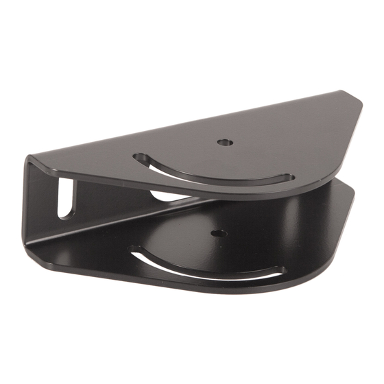
- Page 1 I N S T R U C T I O N S D ' I N S T A L L A T I O N M O N T A G E A N L E I T U N G Angled Ceiling Adapter Adaptateur angulaire pour plafond Adapter für schräge Decken CPA395...
-
Page 2: Installation Instructions
NOTE: Accessory is intended to be used with the UL Listed CPA Extension Column Series (not included). IMPORTANT ! : The CPA395 must be attached to ceiling using two (minimum) 3/8 x 2-1/2" lag bolts (not included). IMPORTANT SAFETY INSTRUCTIONS! -
Page 3: Dimensions
Installation Instructions CPA395 DIMENSIONS 8.00 203.2 DIMENSIONS: INCHES [MILLIMETERS] TOOLS / PARTS FOR INSTALLATION 1/2" 1/2" B (4) 5/16-18 x 1" A (1) [CPA395] 1/2" nut driver C (4) 5/16" 1/4" D (4) 5/16"... -
Page 4: Assembly And Installation
The following instructions assume a suitable mounting structure and surface exists prior to installation. Using CPA395 plate (A) as a template, mark locations of two pilot holes (See Figure 1). Ensure the marks are in the center of wood joists. - Page 5 Tighten hardware installed in Steps 3 and 4. two 5/16" split lock washers (C) and two 5/16" flat washers (D) through fastener hole in CPA395 into first hole on each Complete installation following mount installation side of extension column. (See Figure 3) instructions.
-
Page 6: Clauses De Non-Responsabilité
Tous droits réservés. avec la série de colonnes d'extension CPA homologuées UL (non incluses). IMPORTANT ! : Le CPA395 doit être fixé au plafond en DIRECTIVES DE SÉCURITÉ IMPORTANTES ! utilisant deux (au minimum) boulons tire-fond de 3/8 x 2-1/2"... -
Page 7: Outils / Pièces Nécessaires À L'installation
Installation Instructions CPA395 DIMENSIONS DIMENSIONS : POUCES [MILLIMÈTRES] OUTILS / PIÈCES NÉCESSAIRES À L'INSTALLATION 12,7 mm 12,7 mm (1/2") (1/2") B (4) 5/16-18 x 1" A (1) [CPA395] 12,7 mm (1/2") tourne-écrou C (4) 5/16" 6,4 mm (1/4") D (4) -
Page 8: Montage Et Installation
(Voir la Figure 1). Assurez-vous que les trous de guidage sont droits. Installez et serrez les deux vis tire-fond (non fournies) de 3/8" x 2-1/2" (minimum) de calibre 2 dans le CPA395 (A) et dans les solives en bois (voir la Figure 2). - Page 9 à tête hexagonale de 5/16-18 x 1" (B), deux rondelles frein fendues de 5/16" (C) et deux rondelles plates de 5/16" (D) dans la fente de réglage du CPA395 et dans le troisième trou de la colonne d'extension. (Voir la Figure 4)
-
Page 10: Wichtige Sicherheitshinweise
CPA395 Installation Instructions HAFTUNGSAUSSCHLUSS • Die maximale Tragkraft des CPA395 ist auf die maximale Tragkraft des innerhalb des Halterungssystems Milestone AV Technologies sowie seine konzerneigenen verwendeten sonstigen Bauelements oder Zubehörteils Unternehmen und Tochtergesellschaften (zusammen "Milestone") mit der jeweils geringsten Tragkraft BESCHRÄNKT. - Page 11 Installation Instructions CPA395 ABMESSUNGEN ABMESSUNGEN: ZOLL [MILLIMETER] WERKZEUG / TEILE FÜR DIE MONTAGE 12,7 mm 12,7 mm (1/2") (1/2") B (4) 5/16-18 x 1" A (1) [CPA395] 12,7 mm (1/2") Mutterndreher C (4) 5/16" 6,4 mm (1/4") D (4) 5/16"...
-
Page 12: Montage Und Installation
CPA395 Installation Instructions MONTAGE UND INSTALLATION WICHTIG! Der CPA395 eignet sich für die Montage an einer Holzbalken doppelten Querverstrebung (152,4 mm / 6" von Mitte zu Mitte) aus 51 mm x 102 mm (2" x 4") Holzbalken zwischen zwei Deckenbalken mit einer Gipskartonbeschichtung von maximal 16 mm (5/8"). - Page 13 Installation Instructions CPA395 Befestigen Sie die Ausziehsäule (nicht mitgeliefert) locker am CPA395, indem Sie zwei selbstschneidende 5/16-18 x 1"-Sechskantschrauben (B) mit zwei 5/16"-Federscheiben (B) x 2 (C) und zwei 5/16"-Unterlegscheiben (D) durch die Befestigungsbohrungen im CPA395 in die jeweils ersten Löcher auf beiden Seiten der Ausziehsäule schrauben.
- Page 14 CPA395 Installation Instructions...
- Page 15 Installation Instructions CPA395...
- Page 16 Europe A Franklinstraat 14, 6003 DK Weert, Netherlands P +31 (0) 495 580 852 F +31 (0) 495 580 845 Chief Manufacturing, a products division Asia Pacific A Office No. 1 on 12/F, Shatin Galleria of Milestone AV Technologies 18-24 Shan Mei Street...

