Publicité
Liens rapides
20 739-04
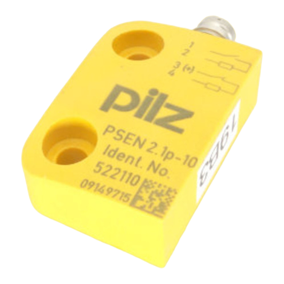
PSEN 2.1p-10, PSEN 2.1p-11, PSEN 2.1p-20, PSEN 2.1p-21
Sicherheitsbestimmungen
• Das Gerät darf nur von Personen installiert
und in Betrieb genommen werden, die mit
dieser Betriebsanleitung und den gelten-
den Vorschriften über Arbeitssicherheit und
Unfallverhütung vertraut sind. Beachten
Sie die VDE- sowie die örtlichen Vorschrif-
ten, insbesondere hinsichtlich Schutzmaß-
nahmen.
• Entfernen Sie die Schutzkappe erst
unmittelbar vor Anschluss des Geräts
Bestimmungsgemäße Verwen-
dung
Die Sicherheitsschalter PSEN 2.1p-10, PSEN
2.1p-11, PSEN 2.1p-20 und PSEN 2.1p-21
sind bestimmt für den Einsatz in Sicherheits-
stromkreisen nach EN 60204-1 und
VDE 0113-1.
Die Sicherheitsschalter erfüllen EN 60947-5-
3 nur zusammen mit zugehörigen Betätigern
• PSEN 2.1p-10/-11 mit Betätiger
PSEN 2.1-10
• PSEN 2.1p-20/-21 mit Betätiger
PSEN 2.1-20
und hierfür zugelassenen Auswertegeräten:
• PNOZ e3.1p
• PNOZ e3vp 10s
• PNOZ e3vp 300s
• PNOZmulti
• Sicherheitssteuerung der Systemfamilie
PSS zusammen mit dem
Standardfunktionsbaustein SB066 (MBS-
Pakete Exzenterpressen, Best.-Nr. 301
172; Hydraulikpressen, Best.-Nr. 301 173;
Transferstraßen, Best.-Nr. 301 175)
Zulassungen/Approvals/
Homologations
Gerätebeschreibung
Zu den Sicherheitsschaltern PSEN 2.1p-10,
PSEN 2.1p-11, PSEN 2.1p-20 und PSEN
2.1p-21 gehört jeweils der Betätiger (Magnet)
PSEN 2.1-10 bzw. PSEN 2.1-20.
Merkmale:
• 2 Reedkontakte (1 Öffner/1 Schließer)
• Wirkweise magnetisch
• Schaltspannung 30 V DC
• PSEN 2.1p-11/PSEN 2.1p-21: mit LED zur
Anzeige des Schaltzustands
Montage
• Die Montagelage ist beliebig. Sicherheits-
schalter und Betätiger müssen jedoch
parallel gegenüberliegend montiert
werden.
• Sicherheitsschalter und Betätiger möglichst
nicht auf ferromagnetisches Material
montieren. Es sind Änderungen der
Schaltabstände zu erwarten. Benutzen Sie
in diesem Fall die Distanzplatte mit der
Bestell-Nr. 534 310.
• Befestigen Sie Sicherheitsschalter und
Betätiger ausschließlich mit Schrauben M4
mit flacher Kopfunterseite (z.B. M4-
Zylinderkopf- oder -Flachkopfschrauben).
Anzugsdrehmoment max. 1 Nm. Verwen-
Safety Regulations
• The unit may only be installed and
operated by personnel who are familiar
with both these instructions and the
current regulations for safety at work and
accident prevention. Follow VDE and local
regulations especially as regards
preventative measures.
• Do not remove the protective cap until you
are about to connect the device.
Authorized applications
The safety switch PSEN 2.1p-10, PSEN
2.1p-11, PSEN 2.1p-20 and PSEN 2.1p-21
are intended for use in safety circuits in
accordance with EN 60204-1 and VDE 0113-
1.
The safety switches only comply with
EN 60947-5-3 in conjunction with the
corresponding actuators
• PSEN 2.1p-10/-11 with actuator
PSEN 2.1-10
• PSEN 2.1p-20/-21 with actuator
PSEN 2.1-20
and approved evaluation devices:
• PNOZ e3.1p
• PNOZ e3vp 10s
• PNOZ e3vp 300s
• PNOZmulti
• Safety control system from the PSS
system range in conjunction with the
standard function block SB066 (MBS
packages Eccentric Press, Order No. 301
172; Hydraulic Press, Order No. 301 173;
Transfer Line, Order No. 301 175)
Description
The safety switch PSEN 2.1p-10, PSEN
2.1p-11, PSEN 2.1p-20 and PSEN 2.1p-21
include the actuator (magnet) PSEN 2.1-10
and PSEN 2.1-20.
Features:
• 2 reed contacts (1 N/C / 1 N/O contact)
• Magnetic operation
• Switching voltage 30 V DC
• PSEN 2.1p-11/PSEN 2.1p-21: with LED
for switch status display
Installation
• The mounting position can be freely
selected. Safety switch and actuator must
be installed parallel and opposite each
other.
• If possible, do not install the safety switch
and actuator on ferromagnetic material.
Changes of the switch offsets are to be
anticipated. In this case, use the distance
plate order no. 534 310.
• The safety switch and actuator should only
be secured using M4 screws on which the
underside of the screw head is flat (e.g.
M4 cheese head or pan head screws).
- 1 -
Conseils préliminaires
• La mise en oeuvre de l'appareil doit être
effectuée par une personne spécialisée en
installations électriques, en tenant compte
des prescriptions des différentes normes
applicables (NF, EN, VDE..), notamment
au niveau des risques encourus en cas de
défaillance de l'équipement électrique.
• Veuillez retirer le cache de protection
avant de raccorder l'appareil.
Domaines d'utilisation
Les capteurs de sécurité PSEN 2.1p-10,
PSEN 2.1p-11, PSEN 2.1p-20 et PSEN 2.1p-
21 sont adaptés pour une utilisation dans les
circuits de sécurité selon les normes EN
60204-1 et VDE 0113-1.
Les capteurs de sécurité sont conformes à la
norme EN 60947-5-3 uniquement lorsqu'ils
sont utilisés avec des organes de commande
(aimants) appropriés
• PSEN 2.1p-10/-11 avec aimant
PSEN 2.1-10
• PSEN 2.1p-20/-21 avec aimant
PSEN 2.1-20
et des appareils de contrôle spécialement
homologués à cet effet :
• PNOZ e3.1p
• PNOZ e3vp 10s
• PNOZ e3vp 300s
• PNOZmulti
• Automates de sécurité de la gamme PSS
avec le bloc fonction standard SB066
(Progiciel Presse Excentrique, réf. 301
172; Presses hydrauliques, réf. 301 173;
Ligne de transfert , réf.301 175)
Description de l'appareil
Les capteurs de sécurité PSEN 2.1p-10,
PSEN 2.1p-11, PSEN 2.1p-20 et PSEN 2.1p-
21 sont utilisés en liaison avec l'actionneur
(aimant) PSEN 2.1-10 et PSEN 2.1-20.
Particularités :
• 2 contacts reed (1 O/1F)
• Action magnétique
• Tension de commutation 30 V DC
• PSEN 2.1p-11/PSEN 2.1p-21 : avec LED
pour affichage status
Installation
• Le sens de montage est indifférent. Le
capteur de sécurité et l'aimant doivent être
montés face à face de façon parallèle.
• Si possible, évitez d'installer le capteur et
l'aimant sur du matériel ferromagnétique.
Les distances de commutation peuvent
être modifiées. Utilisez dans ce cas un
support séparateur de réf. 534 310.
• Pour fixer le capteur de sécurité et
l'aimant, utilisez uniquement des vis M4
dont la tête présente une face inférieure
plate (par ex. une vis M4 cylindrique ou à
tête plate).
Couple de serrage maxi 1 Nm.
Publicité

Manuels Connexes pour Pilz PSEN 2.1p-10


Sommaire des Matières pour Pilz PSEN 2.1p-10
- Page 1 20 739-04 PSEN 2.1p-10, PSEN 2.1p-11, PSEN 2.1p-20, PSEN 2.1p-21 Sicherheitsbestimmungen Safety Regulations Conseils préliminaires • Das Gerät darf nur von Personen installiert • The unit may only be installed and • La mise en oeuvre de l'appareil doit être...
- Page 2 Anschlussleitung gilt nur für die als connection cables only applies to couleurs ne sont valables que pour les Zubehör erhältlichen Kabel von Pilz. cables available from Pilz as an câbles fournis par Pilz. accessory. Der Sicherheitsschalter ist in unbetätigtem The safety switch is shown in not operated Le capteur de sécurité...
- Page 3 Les valeurs indiquées sont valables pour une température de 20°C.) Gesicherter Schaltabstand S in mm/Assured operating distance S in mm/Portée de travail assurée S en mm PSEN 2.1p-10/PSEN 2.1p-11 Höhenversatz/Height offset/Décalage en hauteur PSEN 2.1p-20/PSEN 2.1p-21 Höhenversatz/Height offset/Décalage en hauteur Gesicherter Ausschaltabstand S Assured release distance S Portée de déclenchement assurée S...
- Page 4 0224 2360180, Fax: 0224 2360184 Pilz Automation Safety L.P ., 734 354-0272, Fax: 734 354-3355 www.pilz.com ✆ Pilz GmbH & Co. KG, Sichere Automation, Felix-Wankel-Straße 2, 73760 Ostfildern, Deutschland, +49 711 3409-0, Fax: +49 711 3409-133, E-Mail: pilz.gmbh@pilz.de - 4 -...