Table des Matières
Publicité
Les langues disponibles
Les langues disponibles
Liens rapides
Notre personnel du service à la clientèle est disponible pour vous aider.
Pour obtenir de l'aide pour le montage de votre produit, pour signaler
des pièces endommagées ou manquantes, ou pour toute autre
information, veuillez composer notre numéro sans frais: 1-866-206-0888.
Vous aurez besoin de ce guide pour les règles de sécurité, les procédures d'utilisation et la garantie.
Conservez-le avec votre facture d'origine dans un endroit sûr et au sec pour référence future.
You will need this manual for safety instructions, operating procedures, and warranty.
Put it and the original sales invoice in a safe, dry place for future reference.
CLOUEUSE/AGRAFEUSE
CLOUEUSE/AGRAFEUSE
QUESTIONS? 1-866-206-0888
CONSERVEZ CE GUIDE
SAVE THIS MANUAL
Modèle / Model:
POUR PLANCHER
POUR PLANCHER
Manuel de l'utilisateur (p.2)
FLOORING CLEAT
NAILER/STAPLER
Our Customer service staff is available to help you.
For help with product assembly, to report damaged or missing parts, or
for any other information, please call our toll-free number:
1-866-206-0888.
68125166
PNT162-R
Operator's Manual (p.15)
Publicité
Chapitres
Table des Matières
Dépannage

Sommaire des Matières pour Worksite PNT162-R
- Page 1 68125166 PNT162-R Modèle / Model: CLOUEUSE/AGRAFEUSE CLOUEUSE/AGRAFEUSE POUR PLANCHER POUR PLANCHER Manuel de l'utilisateur (p.2) FLOORING CLEAT NAILER/STAPLER Operator’s Manual (p.15) QUESTIONS? 1-866-206-0888 Notre personnel du service à la clientèle est disponible pour vous aider. Our Customer service staff is available to help you.
-
Page 2: Table Des Matières
TABLE DES MATIÈRES SYMBOLES RÈGLES DE SÉCURITÉ IMPORTANTES CARACTÉRISTIQUES NOMENCLATURE DES PIÈCES MONTAGE PROCÉDURES D’UTILISATION p.11 ENTRETIEN p.11 DÉPANNAGE p.12 GARANTIE p.13 LISTE DES PIÈCES p.14 SCHÉMA AVERTISSEMENT! Les mises en garde et les précautions dont il est question dans le présent manuel ne couvrent pas toutes les conditions et les situations possibles. -
Page 3: Règles De Sécurité Importantes
RÈGLES DE SÉCURITÉ IMPORTANTES INSTRUCTIONS RELATIVES AU RISQUE D'INCENDIE OU AU RISQUE DE BLESSURES. AVERTISSEMENT! Lors de l'utilisation des outils, il est toujours essentiel de suivre les mesures de sécurité de base, y compris celles qui suivent. ZONE DE TRAVAIL Garder la zone de travail propre et bien éclairée. -
Page 4: Utilisation Et Entretien De L'outil
RÈGLES DE SÉCURITÉ IMPORTANTES AVERTISSEMENT! N'enfoncez pas de clou par-dessus un autre clou. Ceci pourrait faire dévier le clou et le diriger vers une personne, ou provoquer un recul de l'outil, ce qui pourrait causer des blessures personnelles. AVERTISSEMENT! Retirez le doigt de la gâchette lorsque vous n'enfoncez pas de fixations. - Page 5 RÈGLES DE SÉCURITÉ IMPORTANTES Ne touchez jamais à la gâchette, sauf lorsque vous enfoncez des clous. Ne jamais fixer le tuyau d'air à l'outil ou transporter l'outil tout en toucher la gâchette. L'outil peut éjecter un projectile qui entraînera la mort ou des blessures graves. Actionnner la gâchette à...
-
Page 6: Alimentation En Air Et Connexions
RÈGLES DE SÉCURITÉ IMPORTANTES laissez l'outil faire le travail. Ne pas tenir compte de cette mise en garde pourrait entraîner des blessures graves. N'enfoncez pas de fixations sur d'autres fixations ou avec l'outil à un angle trop aigu. Ceci pourrait causer le ricochet des fixations et provoquer des blessures. N'actionnez pas l'outil à... -
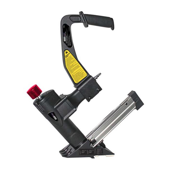
Page 7: Nomenclature Des Pièces
NOMENCLATURE DES PIÈCES La figure 1 identifie les composantes principales de la cloueuse/agrafeuse pour plancher. A. Poignée B. Bras C. Bouchon de frappe D. Bouchon d'air E. Corps F. Plaque en plastique G. Semelle H. Poussoir I. Magasin J. Prise d'air Fig.1 MONTAGE MONTAGE DU BRAS... -
Page 8: Procédures D'utilisation
MONTAGE CHANGEMENT DE LA SEMELLE (Fig.6) AVERTISSEMENT! Débranchez l'outil de la source d'air avant de changer la semelle. Assurez-vous qu'il n'y a pas de fixation dans le magasin avant changer la semelle. Débranchez l'outil de la source d'air. Videz complètement le magasin. Semelle Déclenchez l'outil dans un morceau de bois pour s'assurer qu'il n'y a pas de Vis de la... -
Page 9: Vérification De L'outil Avant Chaque Utilisation
PROCÉDURES D'UTILISATION Raccord de conduite d'air: la cloueuse devrait être équipée d'un raccord rapide mâle de 1/4 po NPT. Pour éviter le déclenchement accidentel même si l'outil est déconnecté, il doit toujours être raccordé à la source d'alimentation d'air de façon à... -
Page 10: Utilisation De L'outil
PROCÉDURES D'UTILISATION UTILISATION DE L’OUTIL Bouchon de AVERTISSEMENT! Un outil qui ne fonctionne pas correctement ne doit pas frappe être utilisé. Ne pas mettre l'outil en marche à moins qu’il ne soit placé bien en position fermement sur la pièce. vers le bas REMARQUE! S’assurer que le butoir de caoutchouc de la cloueuse à... -
Page 11: Entretien
PROCÉDURES D'UTILISATION 4. Réinstallez le nez dans l'ordre inverse (voir l'étape 3). 5. Vérifier que l'outil fonctionne normalement; suivre les étapes de la section "VÉRIFICATION DE L'OUTIL AVANT CHAQUE UTILISATION". Une fois que la vérification est faite, recommencer à utiliser l'outil normalement. AVERTISSEMENT :Omettre de retirer toutes les fixations peut entraîner la projection des fixations restantes à... -
Page 12: Garantie
Fixations déformées GARANTIE Merci d'avoir acheté cet outil WORKSITE. Ces outils ont été conçus pour répondre à des normes de haute qualité très strictes et sont garantis pour usage domestique contre tout défaut de fabrication pour 24 mois suivant la date d'achat. -
Page 13: Liste Des Pièces
LISTE DES PIÈCES Veuillez consulter le schéma à la page suivante. DESCRIPTION DESCRIPTION Maillet Semelle Bouchon de frappe Rondelle 6 Joint torique 25 X 3,55 Boulon M6×35 Boulon M5×25 Semelle Rondelle Boulon M6×14 Bouchon d'air Boulon M5×10 Ressort Boulon M5×14 Joint torique 55,2 X 1,8 Support de magasin Anneau de garniture... - Page 14 SCHÉMA / SCHEMATIC DRAWING...
-
Page 15: Parts List
PARTS LIST Please refer to the Schematic Drawing, on the preceding page. DESCRIPTION DESCRIPTION Mallet Shoe Strike cap Washer 6 O-Ring 25 X 3.55 Bolt M6 X 35 Bolt M5 X 25 Foot plate Washer Bolt M6 X 14 Air Cap Bolt M5 X 10 Spring Bolt M5 X 14... - Page 16 TABLE OF CONTENTS p.14 SCHEMATIC DRAWING p.15 PARTS LIST p.16 SYMBOLS p.17 IMPORTANT SAFETY INSTRUCTIONS p.20 SPECIFICATIONS p.20 FUNCTIONAL DESCRIPTION p.21 ASSEMBLY p.22 OPERATING PROCEDURES p.24 MAINTENANCE p.25 TROUBLESHOOTING p.25 WARRANTY WARNING! The warnings and precautions discussed in the manual cannot cover all possible conditions and situations that may occur.
-
Page 17: Important Safety Instructions
IMPORTANT SAFETY INSTRUCTIONS INSTRUCTIONS PERTAINING TO A RISK OF FIRE, OR PERSONAL INJURY. WARNING! When using tools, basic precautions should always be followed, including the following. WORK AREA Keep the work area clean and well lit. Cluttered benches and dark areas ... - Page 18 IMPORTANT SAFETY INSTRUCTIONS WARNING! Remove finger from the hammer cap (switch) when not driving fasteners. Never carry the tool with finger on hammer cap, the tool is able to fire a fastener. TOOL USE AND CARE Know this tool. Read manual carefully, learn its application and limitations, as well ...
-
Page 19: Tool Service
IMPORTANT SAFETY INSTRUCTIONS Always assume the tool contains fasteners. Respect the tool as a working implement; never play with power tools. Always keep others at a safe distance from the work area in case of accidental discharge of fasteners. Do not point the tool toward yourself or anyone whether it contains fasteners or not. -
Page 20: Specifications
IMPORTANT SAFETY INSTRUCTIONS Use only a pressure-regulated compressed air source to limit the air pressure supplied to the tool. The regulated pressure must not exceed 110 PSI. If the regulator fails, the pressure delivered to the tool must not exceed 120 PSI. The tool could explode which will cause death or serious personal injury. -
Page 21: Assembly
ASSEMBLY ASSEMBLING THE ARM Set the arm (1) to the middle of handle. (Fig.2) Fig.2 Fix the long-set bracket (2) into the hole on the arm. (Fig.3) Fig.3 Put the washer (3) into the bracket and tighten the screw nut (4). (Fig. 4) Fig.4 Insert the washer (3) into the bracket on the opposite side then tighten the screw nut (4). -
Page 22: Operating Procedures
OPERATING PROCEDURES SET UP See the recommended air system setup below (Fig.7). Make sure that the couplers are set up so that the air hose is depressurized when adding or removing components from the system. Oiler Filter Air Supply Cleat nailer / Quick Connector Stapler Air Line... - Page 23 OPERATING PROCEDURES Lock button Staple LOADING STAPLES (Fig.9) Magazine side cover 1. Disconnect air supply. 2. Pull the pusher back to the end of magazine. Lock pusher in the place with the lock button. Then pull the magazine side cover back. 3.
-
Page 24: Maintenance
OPERATING PROCEDURES CAUTION: Clean and inspect the tool daily. Carefully check for proper operation and safety mechanism. Do not use the tool unless the safety mechanism is functional, or if the tool is leaking air or needs any other repair. 2. -
Page 25: Troubleshooting
Use correct fasteners WARRANTY Thank you for investing in a WORKSITE tool. These products have been made to demanding, high-quality standards and are guaranteed for domestic use against manufacturing faults for a period of 24 months from the date of purchase.