
Manuels Connexes pour Valeo CITYSPHERE

Sommaire des Matières pour Valeo CITYSPHERE
- Page 1 AIR CONDITIONING CITYSPHERE Einbau- und Serviceanweisung Installation and Service Instructions Instructions de montage et d’entretien Rev. 07/2018 Id.No. 11112716D...
-
Page 3: Table Des Matières
Citysphere 1. EINLEITUNG 1.1.Bedeutung der Hervorhebungen 1.2.Zusätzlich anzuwendende Dokumente 1.3.Sicherheitshinweise und -bestimmungen 1.4.Zertifizierung 1.5.Verbesserungs- und Änderungsvorschläge 2. ALLGEMEINE BESCHREIBUNG 2.1.Komponenten 2.2.Elektrik 2.3.Funktionsweise der Klimaanlage 2.4.Aufbau, Aufgabe und Funktionsweise der Baugruppen 3. TECHNISCHE DATEN 3.1.Klimaanlage 3.2.Elektrische Sicherungen 3.3.Verdichter Bitzer ECH 209 3.4.Verbindungsschema... - Page 4 Citysphere 6. INSTANDHALTUNG 6.1.Sicherheitshinweise 6.2.Allgemeines 6.3.Wartung und Pflege 6.4.Checkliste Wartung und Pflege 6.5.Prüfungen vor Instandsetzung 6.6.Fehlersuche und Maßnahmen zur Beseitigung 6.7.Instandsetzungsarbeiten 6.8.Prüfungen und Arbeiten nach Instandsetzung 7. GARANTIEABWICKLUNG...
- Page 5 Citysphere Contents 1. INTRODUCTION 1.1.Meaning of emphases 1.2.Additional applicable documentation 1.3.Safety information and regulations 1.4.Certification 1.5.Suggestions for corrections and improvements 2. GENERAL DESCRIPTION 2.1.Components 2.2.Electrical system 2.3.Principle of operation of the air conditioning system 2.4.Design, purpose and principle of operation of the assemblies 3.
- Page 6 Citysphere 5.4.Putting into service for the first time 6. MAINTENANCE 6.1.Safety instructions 6.2.General 6.3.Maintenance and Care 6.4.Maintenance and service checklist 6.5.Inspections before repair 6.6.Troubleshooting 6.7.Repairs 6.8.Post-repair procedures and testing 7. WARRANTY CLAIMS PROCESSING...
- Page 7 Citysphere Sommaire 1. INTRODUCTION 1.1.Signification des signalisations 1.2.Autre documentation à utiliser 1.3.Instructions et prescriptions de sécurité 1.4.Certification 1.5.Suggestions d'amélioration ou de modification 2. DESCRIPTION GENERALE 2.1.Composantes 2.2.Système électrique 2.3.Mode de fonctionnement de la climatisation 2.4.Conception, fonction et mode de fonctionnement des sous-ensembles 3.
- Page 8 Citysphere 5.4.Première mise en service 6. ENTRETIEN 6.1.Consignes de sécurité 6.2.Généralités 6.3.Maintenance et entretien 6.4.Check-list de maintenance et d'entretien 6.5.Contrôles avant réparation 6.6.Recherche des défauts et mesures pour leur élimination 6.7.Travaux de réparation 6.8.Contrôles et travaux après réparation 7. CONDITIONS DE GARANTIE...
-
Page 9: Einleitung
Allgemeine Sicherheitsbestimmungen Die Nichtbeachtung der Einbauanweisung und der darin enthaltenen Hinweise führen zum Haftungsaus- schluss seitens Valeo. Gleiches gilt für nicht fachmännisch oder nicht unter Verwendung von Originalersatz- teilen durchgeführte Reparaturen. Elektrische Leitungen und Bedienelemente der Klimaanlage müssen im Fahrzeug so angeordnet sein, dass ihre einwandfreie Funktion unter normalen Betriebsbedingungen nicht beeinträchtigt werden kann. -
Page 10: Zertifizierung
Die Standards der ECE-Regelung R10 Rev. 05 werden erfüllt. 1.5. Verbesserungs- und Änderungsvorschläge Beanstandungen, Verbesserungen oder Vorschläge zur Berichtigung dieser Anweisung richten Sie bitte an: Valeo Thermal Commercial Vehicles Germany GmbH Friedrichshafener Straße 7 82205 Gilching - Germany Telefon: +49 (0) 8105 7721-0... -
Page 11: Allgemeine Beschreibung
Aufdachklimaanlage Citysphere ALLGEMEINE BESCHREIBUNG Die Aufdachklimaanlage ist zur Kühlung/Klimatisierung und Heizung (nur Comfortversion) von Stadtbussen ausgelegt. Die Aufdachklimaanlage gibt es als Master- und als Slaveversion. Die Master-Anlage enthält alle zum Einbau und Betrieb notwendigen Dokumente und alle zum Betrieb der Anlage notwendigen Komponenten wie Steuergerät, Kabel Bedienteil (2), Bedienteil (3) und Temperatursensoren. -
Page 12: Komponenten
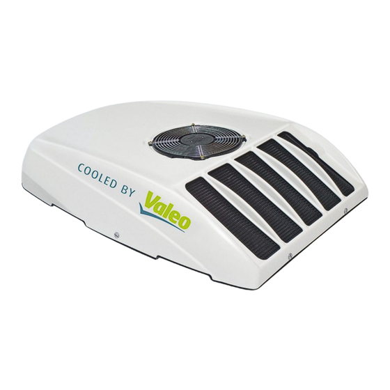
Aufdachklimaanlage Citysphere 2.1. Komponenten Die Aufdachklimaanlage ist in Abb. 2.3 dargestellt. 1 - Haube (äußeres Konturteil) 2 - Grundwanne, als tragendes Strukturteil 3 - Verflüssiger 4 - Verdichter 5 - Verflüssigergebläse 6 - Druckschalter 7 - Sammler/Trockner/Filter für Kältemittel 8 - Füllanschluss HD 9 - Füllanschluss ND... - Page 13 Aufdachklimaanlage Citysphere Abb. 2.3 Seite 5...
-
Page 14: Elektrik
Aufdachklimaanlage Citysphere 2.2. Elektrik Einen Überblick über die Zusammenschaltung der einzelnen Module gibt das Schema in Abb. 3.1. Der elektrische Anschluß der Anlagen erfolgt gemäß Schaltplan in Abb. 3.2 bzw. in Abb. 3.3. Die Aufdachklimaeinheit ist mit einer Batterieentlade-Schutzeinrichtung ausgestattet. Erneute Inbetrieb- nahme erfolgt durch wiederholtes Einschalten. - Page 15 Aufdachklimaanlage Citysphere Der Verdichter mit integriertem Elektromotor läuft an. Er komprimiert das Kältemittelgas und fördert es in den Verflüssiger, wo es unter Wärmeabgabe kondensiert. Die entstehende Kondensationswärme überträgt der Verflüssiger an die durch ihn strömende Außenluft. Dabei sorgt das Axialgebläse auch bei stehendem Fahrzeug für ausreichende Lüftung. Das flüssige Kälte- mittel strömt durch den Sammler-Trockner zum Expansionsventil, es entspannt durch geregelten Druckab-...
-
Page 16: Aufbau, Aufgabe Und Funktionsweise Der Baugruppen
Aufdachklimaanlage Citysphere 2.4. Aufbau, Aufgabe und Funktionsweise der Baugruppen Verflüssiger Der Verflüssiger (3, Abb. 2.3) besteht aus Aluminium-Flachrohren und Aluminium-Lamellen, die zu einer großen Wärmetauscherfläche miteinander verbunden sind. Er kühlt das heiße Kältemittelgas so ab, dass es verflüssigt und unterkühlt, und er überträgt die Kondensa- tionswärme über die Lamellen an die ihn durchströmende Außenluft. - Page 17 Aufdachklimaanlage Citysphere Verdichter Der Verdichter (4, Abb. 2.3) besteht aus einem halbhermetischen Gehäuse mit integriertem Scrollver- dichter, bürstenlosen EC-Motor und Elektronik. Sobald die Kühlfunktion aktiv ist, wird der Verdichter über Pin 1 des Verdichterkabels aktiviert und mit dem erforderlichen Drehzahlsignal angesteuert (PWM-Signal).
-
Page 18: Technische Daten
Aufdachklimaanlage Citysphere TECHNISCHE DATEN 3.1. Klimaanlage Benennung Citysphere Abmessungen (Aufdachklimaeinheit) Länge x Breite x Höhe 1200 mm x 860 mm x 250 mm Gewicht ca. 55 kg Betriebsspannung (entspr. Fahrzeug-Bordnetz) 24 VDC Stromaufnahme Gesamte Stromaufnahme 72 A (max.) – Verdichtermotor 55 A –... -
Page 19: Elektrische Sicherungen
Aufdachklimaanlage Citysphere 3.2. Elektrische Sicherungen Abgesicherte Bauteile Sicherung Sicherungswert Kurzzeichen Druckschalter, Vereisungsschutzschalter, digitaler Eingang Verdichter Verdampfergebläse 15 A Verflüssigergebläse 15 A Relais für elektrische Heizung (nur Comfortversion) Verdichter und falls vorhanden elektrische Heizung 60 A 3.3. Verdichter Bitzer ECH 209 Kältemaschinenöl (Typ / Menge) -
Page 20: Verbindungsschema
Aufdachklimaanlage Citysphere 3.4. Verbindungsschema Abb. 3.1 Seite 12... -
Page 21: Schaltplan Master-Anlage
Aufdachklimaanlage Citysphere 3.5. Schaltplan Master-Anlage Abb. 3.2 Seite 13... -
Page 22: Schaltplan Slave-Anlage
Aufdachklimaanlage Citysphere 3.6. Schaltplan Slave-Anlage Abb. 3.3 Seite 14... -
Page 23: Einbau
Aufdachklimaanlage Citysphere EINBAU 4.1. Sicherheitshinweise Die Sicherheitshinweise gemäß Abschnitt 1.3 sind vor Beginn der Arbeiten zu lesen und zu beachten. Der Einbau soll durch Personen erfolgen, die auf dem Gebiet der Kraftfahrzeugtechnik/Kraftfahr- zeugelektrik sachkundig sind. 4.2. Voraussetzungen für Aufbau – Vor Aufbau und Betrieb der Klimaanlage(n) muss die Stromversorgung des Fahrzeugs auf ausreichende Kapazität überprüft und gegebenenfalls erweitert werden. -
Page 24: Erforderliche Betriebsmittel, Sonderwerkzeug Und Zubehör
Aufdachklimaanlage Citysphere 4.6. Erforderliche Betriebsmittel, Sonderwerkzeug und Zubehör Aufbau auf bestehenden Lukenausschnitt – Schwingsäge zum Entfernen des bestehenden Lukenrahmens – Silikonspray zum Schmieren des Sägeblattes Für Service (Evakuierung, Befüllung und Prüfung des Kältemittelkreislaufs) – Service-Recyclingstation für Kältemittel R134a – Vakuumpumpe, Saugleistung min. 5 m /h, Enddruck 1 mbar –... - Page 25 Aufdachklimaanlage Citysphere – Dachlukenrahmen mit Schwingsäge entfernen. Dazu den Kleber horizontal und vertikal durch- trennen (Sägeblatt mit Silikonspray schmieren). Abb. 4.2 Abb. 4.3 ACHTUNG Keine tragenden Teile (z. B. Spriegel, Versteifungen) oder Einbauten beschädigen. Seite 17...
-
Page 26: Aufkleben Der Anlage
Aufdachklimaanlage Citysphere – Klebereste entfernen und neue Klebefläche reinigen. Abb. 4.4 4.8. Aufkleben der Anlage Die erste Anlage in Fahrtrichtung vorn sollte die Master-Anlage (erkennbar an Steuergerät und Tempera- turfühler) sein. Verflüssiger zeigt in Fahrtrichtung. Die weiteren Anlagen sind Slave-Anlagen und werden von der Master-Anlage gesteuert. - Page 27 Aufdachklimaanlage Citysphere 1010 R100 (970) Fahrtrichtung Lukenausschnitt 970x564, R80 (R80) Mitte Klebenaht 20 bei 970x564 37 bei 970x530 Abb. 4.6 Auf gleichmäßigen Abstand der Halter zum Dach achten. Abb. 4.7 Seite 19...
- Page 28 Aufdachklimaanlage Citysphere – Grundwanne und Dachhaut im Klebebereich aufrauhen analog der Klebenaht (Abb. 4.6 und 4.10), mit Sika-Cleaner reinigen und mit Sika-Primer vorbehandeln (Produkthinweise beachten). Abb. 4.8 Abb. 4.9 Seite 20...
- Page 29 Aufdachklimaanlage Citysphere – Sika-Raupe auf die Dachhaut auftragen und Anlage aufsetzen. Der Klebespalt ergibt sich durch Abstands-Beulen in der Klebefläche der Grundwanne. Abb. 4.10 – Von der Businnenseite aus ringsum prüfen, ob alles richtig abgedichtet ist. Abb. 4.11 – Hintere und mittlere Halter mit Sika fixieren und mit Innensechskantschraube am oberen Gegenhalter festschrauben.
-
Page 30: Elektrische Verbindungen Herstellen
Aufdachklimaanlage Citysphere 4.9. Elektrische Verbindungen herstellen Die Anlage ist fahrzeugseitig mit maximal 100 A direkt nach der Batterie abzusichern. Der Kabelquerschnitt ist folgendermaßen festzulegen: Mindestquerschnitt 25 mm , ab einer Kabellänge (einfache Länge) von 19 m ist ein Querschnitt von 35 mm zu verwenden und ab einer Länge von 26 m bis zu 38 m ist ein Querschnitt von 50 mm... - Page 31 Aufdachklimaanlage Citysphere Abb. 4.14 Abb. 4.15 – Kabelbaum mit Klemme 15 und D+ (Klemme 61) verbinden (bei Klemme 15 Sicherungshalter und Sicherung 5 A zwischenschalten). – Kabel in Schutzhüllen verlegen und mit Kabelbindern ausreichend befestigen. – Kabel gemäß Farbcodierung an den 4-poligen Klemmverbinder der Master-Anlage anschließen.
-
Page 32: Luftverteiler Montieren
Aufdachklimaanlage Citysphere 4.10. Luftverteiler montieren – Zuerst die vorderen Gewindestangen einstellen und kontern. Danach die restlichen Gewindestangen auf die gleiche Höhe einstellen und kontern. Innenverkleidung * Achtung: Beim Festziehen an der oberen Mutter gegenhalten. Abb. 4.16 – Innenverkleidung ausschneiden, Abstand zu den Gewindestangen ca. 20-30 mm (820x530). - Page 33 Aufdachklimaanlage Citysphere – Schaumstoff rundum zwischen Dach und Deckeninnenverkleidung einbringen, um zu vermeiden, dass Luft aus dem Deckenbereich angesaugt wird. Abb. 4.18 – Hut auf dem Luftverteiler ausrichten und festnieten. – Luftverteiler montieren. Darauf achten, dass er mit der Innenverkleidung des Daches fluchtet und dass der Hut umlaufend an der Dichtung der Grundwanne anliegt.
-
Page 34: Haube Montieren
Aufdachklimaanlage Citysphere – Gebläsestecker verbinden und mit Kabelband gegen Scheuern sichern. – Luftansauggitter befestigen. Abb. 4.20 4.11. Haube montieren – Luftfilter auf richtigen Sitz kontrollieren. Luftfilter Abb. 4.21 – Nach Aufsetzen der Haube das Verflüssigergebläse anstecken. Das Kabel möglichst weit auf die in Fahrtrichtung gesehen rechte Seite ziehen. -
Page 35: Inbetriebnahme
Aufdachklimaanlage Citysphere INBETRIEBNAHME 5.1. Sicherheitshinweise Die Sicherheitshinweise gemäß Kap. 1.3 sind zu beachten. VORSICHT Inbetriebnahme der Anlage nur mit montierter Haube und montiertem Luft- verteiler. Verletzungsgefahr durch die Gebläse. 5.2. Bedienerhinweise ACHTUNG Die Klimaanlage kann nur bei laufendem Fahrzeugmotor in Betrieb genommen werden. -
Page 36: Instandhaltung
Aufdachklimaanlage Citysphere INSTANDHALTUNG 6.1. Sicherheitshinweise Die Sicherheitshinweise und –vorschriften gemäß Abschnitt 1.3 sind zu beachten. 6.2. Allgemeines Alle Arbeiten am Kältemittelkreislauf sind nur von sachkundigem Personal autorisierter Fachwerk- stätten auszuführen. Zu Instandhaltungsarbeiten am Klimakreislauf sind die in Kapitel 4.6 aufgeführten speziellen Be- triebsmittel, Sonderwerkzeuge sowie Zubehörteile erforderlich und einzusetzen. -
Page 37: Checkliste Wartung Und Pflege
Aufdachklimaanlage Citysphere 6.4. Checkliste Wartung und Pflege Häufigkeit Anlagenteil Wartungsarbeiten Kältemittelkreislauf – Anschlüsse Dichtigkeitsprüfung mit Lecksuchgerät durchführen – Verflüssiger Lamellen auf Zustand prüfen (bei Verschmutzung reinigen) – Kondenswasserablauf Öffnungen prüfen und ggf. reinigen – Aufdachklimaeinheit Gesamtzustand und Anschlußstellen auf festen Sitz prüfen Verdichter –... -
Page 38: Fehlersuche Und Maßnahmen Zur Beseitigung
Aufdachklimaanlage Citysphere 6.6. Fehlersuche und Maßnahmen zur Beseitigung 6.6.1. Allgemeines Bei der Fehlersuche und deren Beseitigung ist eine systematische Vorgehensweise zweckmäßig. Entsprechende Maßnahmen bei Störungen allgemeiner Art oder Abweichungen von Sollzuständen bei der Druckprüfung sind wie unten beschrieben durchzuführen. Bestimmte Fehler können nur durch sachkundiges Personal mit Spezialwerkzeug festgestellt und behoben werden. -
Page 39: Instandsetzungsarbeiten
Aufdachklimaanlage Citysphere Druck am Niederdruckmanometer zu hoch – Expansionsventil fehlerhaft – Verdichterdrehzahl zu niedrig – Verdichter defekt Druck am Niederdruckmanometer zu gering – Drosselung in der Saug- oder Druckleitung z.B. durch Leitungsknicke – Expansionsventil fehlerhaft – Kältemittelmenge zu gering – zu geringer Luftdurchsatz am Verdampfer –... - Page 40 Aufdachklimaanlage Citysphere Es müssen sich folgende ca. Werte ergeben: Außentemperatur Niederdruckmanometer Hochdruckmanometer = Innentemperatur 17°C 2,7 ± 0,2 bar 8,4 ± 2 bar 20°C 2,9 ± 0,2 bar 9,0 ± 2 bar 25°C 3,3 ± 0,2 bar 10,3 ± 2 bar 30°C...
-
Page 41: Garantieabwicklung
Aufdachklimaanlage Citysphere GARANTIEABWICKLUNG Im Garantiefall an die zuständige Handelsorganisation wenden. Seite 33... - Page 42 Aufdachklimaanlage Citysphere Seite 34...
-
Page 43: Meaning Of Emphases
The specific safety regulations are highlighted in the individual chapters resp. procedures. General safety regulations Non-compliance with the installation manual and its included notes will lead to liability exclusion by Valeo. The same applies to unskilled repairs or repairs not using original spare parts. -
Page 44: Certification
Rooftop Air Conditioning System Citysphere Safety instructions for maintenance If faults develop in the refrigerant circuit, the system must be tested and repaired by an authorized specialist repair shop according to the rules. Under no circumstances may refrigerant be discharged into the atmosphere. -
Page 45: General Description
Rooftop Air Conditioning System Citysphere GENERAL DESCRIPTION The rooftop air conditioning system is designed for the cooling / air conditioning and heating (comfort version only) of city buses. The rooftop air conditioning system is available as master- and as slave-version. With the master unit come all the documents required for installation and all components necessary for operation such as the control device, control panel cables (2), the control panel (3) and the temperature sensors. -
Page 46: Components
Rooftop Air Conditioning System Citysphere 2.1. Components The rooftop airconditioner-unit is shown in Fig. 2.3. 1 - Hood (external contour element) 2 - Baseplate as the load-bearing structural element 3 - Condenser 4 - Compressor 5 - Condenser fan 6 - Pressure switch... - Page 47 Rooftop Air Conditioning System Citysphere Fig. 2.3 Page 39...
-
Page 48: Electrical System
Rooftop Air Conditioning System Citysphere 2.2. Electrical system An overview about the connection of the modules among each other is given in diagram Fig. 3.1. The hook-up of the units shall be accomplished according to the circuit diagrams in Fig. 3.2 and Fig. 3.3. - Page 49 Rooftop Air Conditioning System Citysphere The compressor with integrated electric motor runs up. It compresses the refrigerant gas and delivers it to the condenser where it condenses and gives off heat. The resultant condensation heat is transferred to the outside air flowing through the condenser. In this process the axial fan maintains a sufficient ventilation even when the vehicle is stationary.
-
Page 50: Design, Purpose And Principle Of Operation Of The Assemblies
Rooftop Air Conditioning System Citysphere 2.4. Design, purpose and principle of operation of the assemblies Condenser The condenser (3, Fig. 2.3) consists of aluminium flat pipes and fins interconnected to form a large heat exchanger surface. It cools the hot refrigerant gas so that the latter liquefies and undercools. And transfers the condensation heat to the outside air flowing through it via the fins, at the same time. - Page 51 Rooftop Air Conditioning System Citysphere Compressor The compressor (4, Fig. 2.3) comprises a semi-hermetic housing with integrated scroll compressor, brushless DC motor, and electronics. When the air conditioning system is switched on, the compressor will be activated via pin 1 of the compressor's cable harness, and driven with the required revs per minute (PWM-signal).
-
Page 52: Technical Data
Rooftop Air Conditioning System Citysphere TECHNICAL DATA 3.1. Air conditioning system Designation Type Citysphere Dimensions, rooftop air conditioning unit Length x width x height 1,200 mm x 860mm x 250mm Weight approx. 55 kg Operating voltages (depending on vehicle's electr. -
Page 53: Electrical Fuses
Rooftop Air Conditioning System Citysphere 3.2. Electrical fuses Protected components Fuse Fuse ratings Letter symbol Pressure switch, anti-icing switch, Digital input compressor Radial fan 15 A Axial fan 15 A Relays for heating (comfort version only) Compressor and heating, if present 60 A 3.3. -
Page 54: Connecting Scheme
Rooftop Air Conditioning System Citysphere 3.4. Connecting scheme Fig. 3.1 Page 46... -
Page 55: Circuit Diagram Master Unit
Rooftop Air Conditioning System Citysphere 3.5. Circuit diagram master unit Fig. 3.2 Page 47... -
Page 56: Circuit Diagram Slave Unit
Rooftop Air Conditioning System Citysphere 3.6. Circuit diagram slave unit Fig. 3.3 Page 48... -
Page 57: Installation
Rooftop Air Conditioning System Citysphere INSTALLATION 4.1. Safety instructions The safety instructions set out in chapter 1.3 must be read and noted before starting work. Installation should be performed by someone well versed in auto mechanics/auto electrics. 4.2. Conditions for assembly –... -
Page 58: Required Equipment, Special Tools And Accessories
Rooftop Air Conditioning System Citysphere 4.6. Required equipment, special tools and accessories Installation on existing hatch cut-out – Jigsaw to remove existing hatch frame – Silicone spray for lubricating the saw blade For service (evacuation, filling and testing the refrigerant circuit) –... -
Page 59: Important
Rooftop Air Conditioning System Citysphere – Remove dormer window frame with jigsaw. To that, sever adhesion horizontally and vertically (lubricate saw blade with silicone spray). Fig. 4.2 Fig. 4.3 IMPORTANT Ensure that load-bearing elements (e.g. roof hoops, reinforcements) and installed parts are not damaged. -
Page 60: Adhesive Bonding Of The Unit
Rooftop Air Conditioning System Citysphere – Remove adhesion remainder and clean new adhesion surface. Fig. 4.4 4.8. Adhesive bonding of the unit The first unit in front in direction of travel should be the master unit (recognizable by control and temperature sensor). - Page 61 Rooftop Air Conditioning System Citysphere 1010 R100 (970) Direction of travel Roof hatch size 970x564, R80 (R80) Adhesive joint center line 20 at 970x564 37 at 970x530 Fig. 4.6 Keep an eye on an equal distance of the brackets to the roof.
- Page 62 Rooftop Air Conditioning System Citysphere – Roughen bonding area of baseplate and roof surface according to the adhesive joint (Ref. Fig. 4.6 and Fig. 4.10), clean with Sika Cleaner, and preprocess with Sika Primer (follow product information). Fig. 4.8 Fig. 4.9...
- Page 63 Rooftop Air Conditioning System Citysphere – Spread Sika adhesive on the roof surface and place unit. The required bonding gap results from the spacer dents in the bonding surface of the baseplate. Fig. 4.10 – From inside of the bus check all around whether all is sealed up properly.
-
Page 64: Establish Electrical Connections
Rooftop Air Conditioning System Citysphere 4.9. Establish electrical connections The system must be protected on the vehicle side with max. 100 A direct after the battery. The cable cross- section must be determined as follows: Minimum cross-section 25 mm , from a cable length (single length) of 19 m a cross-section of 35 mm to be used, and from a length of 26 m to 38 m a cross-section of 50 mm Refer also to “Copper cables for use in motor vehicles”... - Page 65 Rooftop Air Conditioning System Citysphere Fig. 4.14 Fig. 4.15 – Connect cable harness with terminal 15 and D+ (terminal 61) (interpose fuse bracket at terminal 15 and fuse 5A). – Route cables through protective sleeves and secure them appropriately with cable ties.
-
Page 66: Mount Air-Diffusor
Rooftop Air Conditioning System Citysphere 4.10. Mount air-diffusor – First adjust the forward thread rods in height and lock. Then adjust the remaining thread rods to the same height and lock. Lining * Attention: While tightening, fix the upper nut. - Page 67 Rooftop Air Conditioning System Citysphere – Affix foam outright in the gap between roof and inner ceiling lining to avoid that air is drawn from the ceiling area. Fig. 4.18 – Align hood on the air-diffusor and rivet. – Install air-diffusor. Pay attention that it aligns with the inner ceiling lining, and that the hood fits closely round about to the seal of the baseplate.
-
Page 68: Mount Hood
Rooftop Air Conditioning System Citysphere – Connect fan plug and secure with cable tape against chafing. – Fasten intake air grille. Fig. 4.20 4.11. Mount hood – Check air filter for correct fit.. Air filter Fig. 4.21 – After hood installation plug in the electrical connector of the condenser fan. Pull the cable as far as possible to the right side facing the direction of travel. -
Page 69: Startup
Rooftop Air Conditioning System Citysphere STARTUP 5.1. Safety instructions The safety instructions in chapter 1.3 must be observed. WARNING The system may only be started when the hood and air-distribution panel have been fitted. Risk of injury due to motor fans. -
Page 70: Maintenance And Care
Rooftop Air Conditioning System Citysphere MAINTENANCE 6.1. Safety instructions The safety instructions and regulations in chapter 1.3 must be observed. 6.2. General All work on the refrigerant circuit may only be carried out by qualified personnel from duly authorized specialist repair shops. - Page 71 Rooftop Air Conditioning System Citysphere 6.4. Maintenance and service checklist Frequency System component Maintenance tasks Refrigerant circuit – Connections Test for leaks with leak tester – Condenser Check condition of fins (must be cleaned if soiled) – Condensation water Check openings and clean if necessary drain –...
- Page 72 Rooftop Air Conditioning System Citysphere 6.6. Troubleshooting 6.6.1. General A systematic approach is advisable for troubleshooting. Appropriate action must be undertaken as described below for faults of a general nature or when normal conditions are not obtained during the pressure test.
- Page 73 Rooftop Air Conditioning System Citysphere Low pressure gauge reading too low – Intake or delivery line restricted, e.g. by kinks – Expansion valve defective – Not enough refrigerant – Evaporator air flow restricted – Collector/drier clogged 6.7. Repairs IMPORTANT Under no circumstances may refrigerant be discharged into the atmosphere.
-
Page 74: Visual Inspection
Rooftop Air Conditioning System Citysphere The following approx. values must be obtained: Outside air Low pressure gauge High pressure gauge temperature =Indoor temperature 62.60°F 2.7 ± 0.2 bar 8.4 ± 2 bar 68.00°F 2.9 ± 0.2 bar 9.0 ± 2 bar 77.00°F... - Page 75 Rooftop Air Conditioning System Citysphere WARRANTY CLAIMS PROCESSING In the event that a warranty claim arises, contact your local distributor. Page 67...
- Page 76 Rooftop Air Conditioning System Citysphere Page 68...
- Page 77 Le non-respect de la notice de montage et d'entretien et des indications qu'elle contient entraîne l'exclusion de toute responsabilité de la part de la société Valeo. Il en est de même pour les travaux de réparation non conformes ou pour des réparations effectuées avec des pièces qui ne sont pas des pièces de rechange originales.
-
Page 78: Suggestions D'amélioration Ou De Modification
Les normes du règlement ECE R10 Rev. 05 sont remplies. 1.5. Suggestions d'amélioration ou de modification Veuillez adresser vos réclamations, suggestions d'amélioration ou de rectification de cette notice à : Valeo Thermal Commercial Vehicles Germany GmbH Friedrichshafener Straße 7 82205 Gilching - Germany Telefon:... -
Page 79: Description Generale
Climatisation sur toiture Citysphere DESCRIPTION GENERALE La climatisation sur toiture est conçue pour le refroidissement/la climatisation et le chauffage (uniquement la version Comfort) des bus. La climatisation sur toiture existe en version maître et en version esclave. L'unité maître contient tous les documents nécessaires à... - Page 80 Climatisation sur toiture Citysphere 2.1. Composantes La climatisation sur toiture est représentée à la Fig. 2.3. 1 - Capot (partie du bord extérieur) 2 - Plaque de base constituant la partie portante 3 - Condenseur 4 - Compresseur 5 - Ventilateur du condenseur 6 - Pressostat 7 - Collecteur / déshydrateur / filtre pour réfrigérant...
- Page 81 Climatisation sur toiture Citysphere Fig. 2.3 Page 73...
-
Page 82: Système Électrique
Climatisation sur toiture Citysphere 2.2. Système électrique Le schéma Fig. 3.1 donne une vue d'ensemble de la commutation des différents modules. Le branchement électrique de l'équipement s'effectue selon les schémas électriques des Fig. 3.2 et Fig. 3.3. La climatisation sur toiture est équipée d'un circuit de protection contre la décharge de la batterie. La remise en service s'effectue par simple redémarrage. - Page 83 Climatisation sur toiture Citysphere Le compresseur à moteur électrique intégré se met en marche. Il comprime le gaz réfrigérant et le refoule vers le condenseur, où il se condense en dégageant de la chaleur. Le condenseur transmet la chaleur de condensation produite à l'air extérieur qui le traverse. Le ventilateur axial assure une ventilation suffisante même lorsque le véhicule est à...
- Page 84 Climatisation sur toiture Citysphere 2.4. Conception, fonction et mode de fonctionnement des sous-ensembles Condenseur Le condenseur (3, Fig. 2.3) est composé de serpentins et d'ailettes en aluminium reliés entre eux pour former une grande surface d'échangeur thermique. Il refroidit le gaz réfrigérant chaud de manière à ce que celui-ci se liquéfie et devienne très froid et il transmet la chaleur produite par la condensation à...
- Page 85 Climatisation sur toiture Citysphere Compresseur Le compresseur (4, Fig. 2.3) est constitué d'un boîtier semi-hermétique à compresseur scroll intégré, d'un moteur à courant continu sans balais et de composants électroniques. Dès la mise en marche de la fonc- tion, le compresseur est activé via la broche 1 du faisceau de câbles et piloté à la vitesse de rotation nécessaire (signal PWM).
-
Page 86: Donnees Techniques
Climatisation sur toiture Citysphere DONNEES TECHNIQUES 3.1. Climatisation Désignation Citysphere Dimensions (unité de climatisation sur toiture) Longueur x largeur x hauteur 1200 mm x 860 mm x 250 mm Poids environ 55 kg Tension de service (suivant réseau de bord véhicule) -
Page 87: Fusibles Électriques
Climatisation sur toiture Citysphere 3.2. Fusibles électriques Sous-ensembles protégés Fusible Intensité Abréviation Pressostat, thermostat anti-gel Entrée numérique compresseur Ventilateur de l'évaporateur 15 A Ventilateur du condenseur 15 A Relais de chauffage (seulement sur la version Comfort) Compresseur et chauffage, le cas échéant 60 A 3.3. - Page 88 Climatisation sur toiture Citysphere 3.4. Schéma de raccordement Fig. 3.1 Page 80...
-
Page 89: Schéma Électrique Unité Maître
Climatisation sur toiture Citysphere 3.5. Schéma électrique Unité maître Fig. 3.2 Page 81... - Page 90 Climatisation sur toiture Citysphere 3.6. Schéma électrique Unité esclave Fig. 3.3 Page 82...
-
Page 91: Consignes De Sécurité
Climatisation sur toiture Citysphere MONTAGE 4.1. Consignes de sécurité Lire les consignes de sécurité du chapitre « 1.3 » avant de commencer les travaux et les respecter. Le montage doit être effectué par un personnel spécialisé dans les domaines de l'automobile et de l'électricité... -
Page 92: Préparation De La Toiture Du Véhicule
Climatisation sur toiture Citysphere 4.6. Matériel d'équipement nécessaire, outillage spécifique et accessoires Montage sur ouverture de secours existante – Scie pour enlever le cadre de l'ouverture de secours existante – Spray silicone pour lubrifier la lame de scie Pour l'entretien (évacuation, remplissage et contrôle du circuit de réfrigération) –... - Page 93 Climatisation sur toiture Citysphere – Enlever le cadre de l'ouverture de secours à l'aide de la scie. Pour cela, séparer le joint horizon- tal du joint vertical (graisser la lame de la scie à l'aide du spray silicone). Fig. 4.2 Fig.
- Page 94 Climatisation sur toiture Citysphere – Enlever les traces de colle et nettoyer les nouvelles surfaces collantes. Fig. 4.4 4.8. Coller l'installation La première unité dans le sens de la conduite devrait être l'unité maître (reconnaissable à l'appareil de commande et à la sonde de température). Le condenseur est à monter dans le sens de la conduite.
- Page 95 Climatisation sur toiture Citysphere 1010 R100 (970) Sens de la conduite Découpe de l'ouverture 970x564, R80 (R80) Milieu couture collée 20 pour 970x564 37 pour 970x530 Fig. 4.6 Veiller à ce que les supports soient à égale distance du toit.
- Page 96 Climatisation sur toiture Citysphere – Dépolir la plaque de base et le toit dans la zone de collage (Fig. 4.6 et Fig. 4.10), les nettoyer avec du nettoyant Sika Cleaner et les pré-traiter avec Sika Primer (respecter les indications du produit).
- Page 97 Climatisation sur toiture Citysphere – Mettre une couche de Sika-Raupe sur le toit et y déposer l'équipement. L'espace de collage nécessaire est créé par des encoches dans la surface collante de la plaque de base. Fig. 4.10 – Vérifier de l'intérieur du bus si tout est bien étanché tout autour.
-
Page 98: Effectuer Les Raccordements Électriques
Climatisation sur toiture Citysphere 4.9. Effectuer les raccordements électriques L'équipement doit être protégé, côté véhicule, directement après la batterie, à 100 A maxi. La section des câbles est déterminée de la façon suivante: Section minimale 25 mm , à partir d'une longueur de câble (longueur simple) de 19 m, utiliser une section de 2 et à... - Page 99 Climatisation sur toiture Citysphere Fig. 4.14 Fig. 4.15 – Raccorder le faisceau de câbles avec la borne 15 et D+ (borne 61) (sur la borne 15, intercon- necter le porte-fusible et le fusible 5 A). – Poser les câbles dans des gaines de protection et les fixer avec des attache-câbles.
-
Page 100: Monter Le Répartiteur D'air
Climatisation sur toiture Citysphere 4.10. Monter le répartiteur d'air – Monter d'abord les tiges filetées avant et les arrêter. Puis monter les autres tiges filetées à la même hauteur et les arrêter. Habillage intérieur * Attention: En serrant, bien tenir l'écrou supérieur. - Page 101 Climatisation sur toiture Citysphere – Apposer de la mousse tout autour de l'ouverture entre les toits extérieur et intérieur afin d'empêcher l'aspiration d'air du toit. Fig. 4.18 – Ajuster le couvercle sur le répartiteur d'air et le fixer à l'aide de rivets.
-
Page 102: Monter Le Capot
Climatisation sur toiture Citysphere – Raccorder les prises du ventilateur et les protéger des frottements avec du ruban pour câbles. – Fixer la tôle d'aspiration d'air. Fig. 4.20 4.11. Monter le capot – Contrôler le bon positionnement du filtre à air. -
Page 103: Instructions Pour L'utilisateur
Climatisation sur toiture Citysphere MISE EN SERVICE 5.1. Consignes de sécurité Respecter les consignes de sécurité indiquées au chapitre 1.3. AVERTISSEMENT L'équipement ne doit être mis en service que lorsque le capot est fermé et le répartiteur d'air monté. Risque de blessure par les ventilateurs. -
Page 104: Maintenance Et Entretien
Climatisation sur toiture Citysphere ENTRETIEN 6.1. Consignes de sécurité Respecter les consignes et les prescriptions de sécurité indiquées au chapitre 1.3. 6.2. Généralités Tous les travaux sur le circuit de réfrigération ne sont à effectuer que par un personnel compétent et qualifié... -
Page 105: Check-List De Maintenance Et D'entretien
Climatisation sur toiture Citysphere 6.4. Check-list de maintenance et d'entretien Fréquence Partie de l'installation Travaux de maintenance Circuit de réfrigération – Raccords Vérifier l'étanchéité à l'aide d'un détecteur de fuites – Condenseur Vérifier le bon état des ailettes (nettoyer si encrassées) –... -
Page 106: Recherche Des Défauts Et Mesures Pour Leur Élimination
Climatisation sur toiture Citysphere 6.6. Recherche des défauts et mesures pour leur élimination 6.6.1. Généralités Une méthode systématique est à adopter pour la recherche de défauts et leur élimination. Les me- sures correspondantes en cas de perturbations à caractère général ou d'écarts par rapport aux va- leurs théoriques lors du contrôle de la pression sont à... -
Page 107: Travaux De Réparation
Climatisation sur toiture Citysphere Pression du manomètre de basse pression trop basse – Obstruction dans la conduite d'aspiration ou de pression dû, par exemple, à un coude dans le flexible – Détendeur défectueux – Quantité trop faible de réfrigérant – Débit d'air dans l'évaporateur trop faible –... -
Page 108: Contrôle Visuel
Climatisation sur toiture Citysphere On doit obtenir des valeurs proches des valeurs suivantes : Température Manomètre basse pression Manomètre haute pression extérieure =température intérieure 17°C 2,7 ± 0,2 bars 8,4 ± 2 bars 20°C 2,9 ± 0,2 bars 9,0 ± 2 bars 25°C... -
Page 109: Conditions De Garantie
Climatisation sur toiture Citysphere CONDITIONS DE GARANTIE En cas de garantie, s'adresser à l'instance appropriée. Page 101... - Page 110 memos...
- Page 111 Valeo Thermal Commercial Vehicles Germany GmbH Friedrichshafener Str. 7 - 82205 Gilching - Germany - Tel. +49 (0)8105 7721-0 - Fax +49 (0)8105 7721-889 www.valeo-thermalbus.com - service-valeobus@valeo.com...