Publicité
Les langues disponibles
Les langues disponibles
Liens rapides
No: 25514 – 10/17 rev. 2
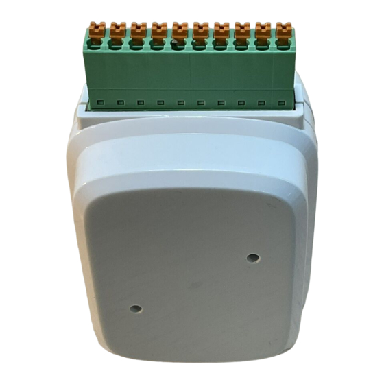
Catalog Number • Numéro de Catalogue • Número de Catálogo: LMOR-102
Country of Origin: Made in China • Pays d'origine: Fabriqué en Chine • País de origen: Hecho en China
LMOR-102-U is BAA and TAA compliant (Product produced in the U.S.)
Installation shall be in accordance with
all applicable regulations, local and NEC
codes. Wire connections shall be rated
suitable for the wire size (lead and building
wiring) employed.
For Class 2 DLM devices and device wiring:
To be connected to a Class 2 power source
only. Do not reclassify and install as Class 1,
or Power and Lighting Wiring.
The LMOR-102 allows Digital Lighting Management products to signal and control 3rd party devices via low voltage contact closures.
The LMOR-102 connects to the DLM local network, and its isolated relays can be bound to and controlled by DLM occupancy sensors,
push button switches, photocells, or other DLM devices that can control loads in a space. While most DLM loads are line voltage, this
unit allows the use of "dry" (unpowered) low voltage contacts.
The LMOR-102 operates on power from the DLM local network. It contains two 24VDC mechanically held isolated relays (single-pole,
double throw with normally open (N.O.), normally closed (N.C.), and common outputs) for output to other systems.
Outputs: Isolated Relay, 24VDC
Each isolated relay can respond to any DLM occupancy sensor or sensors on the DLM local network to provide their occupancy
status to a third party interface, such as HVAC or other controlling systems. When controlled by multiple sensors, if any sensor is in an
occupied state, the relay's N.O. contact will be closed.
Interface Buttons
The LMOR-102 is similar to the LMRC-102 except that rather than provide a line voltage outputs, it provides two "dry" (unpowered), low
voltage, normally open or normally closed contact closures, for use with any 3rd party device that uses max 24VAC/DC inputs.
The LMOR-102 includes a configuration button that can be used to initiate DLM's Push n Learn programming sequence, and a Red
LED to provide feedback during the PnL process.
Additionally, two override buttons are located on the unit - one for each relay - so that the wiring from the LMOR-102 to the 3rd party
hardware can be tested at any time. A blue status LED is also provided per relay.
Wattstopper
Low Voltage Dual Relay Interface
Interface de relais à basse tension double
Interfaz de Bajo Voltaje con dos Relés
Installation Instructions • Instructions d'Installation • Instrucciones de Instalación
Voltage .............................................................................. 24VDC
Current Consumption ...........................................................10mA
Power Supply ................................. Wattstopper Room Controller
Connection to the DLM Local Network .................... 2 RJ-45 ports
Isolated Relay Ratings ................. Dual mechanically held relays,
..................................max. per relay, 1A 24VAC/VDC SPDT
normally open (N.O.), normally closed (N.C.), and common
terminals
Terminal wire size .......................................................16–28 AWG
Environment ................................................. For Indoor Use Only
Operating Temperature .................32° to 104°F (0° to 40°C)
Storage Temperature ...................23° to 176°F (-5° to 80°C)
Relative Humidity .......................5 to 95% (non condensing)
RoHS compliant, UL2043 Plenum rated
Patent Pending
DESCRIPTION
OPERATION
®
SPECIFICATIONS
Publicité

Manuels Connexes pour LEGRAND Wattstopper LMOR-102


Sommaire des Matières pour LEGRAND Wattstopper LMOR-102
- Page 1 Wattstopper ® Low Voltage Dual Relay Interface Interface de relais à basse tension double Interfaz de Bajo Voltaje con dos Relés No: 25514 – 10/17 rev. 2 Installation Instructions • Instructions d’Installation • Instrucciones de Instalación Catalog Number • Numéro de Catalogue • Número de Catálogo: LMOR-102 Country of Origin: Made in China •...
- Page 2 MOUNTING AND WIRING CAUTION: TO CONNECT A COMPUTER TO THE DLM LOCAL NETWORK USE THE LMCI-100. NEVER CONNECT THE DLM LOCAL NETWORK TO AN ETHERNET PORT – IT MAY DAMAGE COMPUTERS AND OTHER CONNECTED EQUIPMENT. Installation shall be in accordance with all applicable regulations, wiring practices, and codes.
- Page 3 POWER UP FUNCTIONALITY BUTTONS AND LED INDICATORS Upon initial power up, the LMOR-102 will go into it’s initial Config: This LED will be blink Plug n’ Go™ settings. It will communicate with all other load every three seconds when the control DLM devices inside the space, and it’s two relays will be LMIO-102 is in Run mode.
- Page 4 DLM fourni avec Wattstopper contrôleurs de pièce et aussi disponible au Bloc d’alimentation ......Contrôleur de pièce Wattstopper www.legrand.us/wattstopper. Branchement au réseau local DLM ........ 2 ports RJ-45 Caractéristiques nominales du relais isolé ....Relais doubles L’installation doit être effectuée conformément à...
- Page 5 MONTAGE ET CÂBLAGE ATTENTION : POUR CONNECTER UN ORDINATEUR AU RÉSEAU DLM LOCAL, UTILISER LA LMCI-100. NE BRANCHEZ JAMAIS LE RÉSEAU DLM LOCAL À UN PORT ETHERNET – CELA POURRAIT ENDOMMAGER LES ORDINATEURS AINSI QUE LES AUTRES ÉQUIPEMENTS CONNECTÉS. L’installation doit être conforme à toutes réglementations, les pratiques de câblage et les Codes en vigueur.
- Page 6 FONCTIONNALITÉ DE MISE SOUS TENSION BOUTONS ET TÉMOINS DEL Lors de la première mise sous tension, le LMOR-102 passera Config. : Ce témoin DEL aux réglages Plug n’GoMC d’origine. Il communiquera avec clignotera toutes les 3 tous les autres dispositifs de contrôle de charge DLM à secondes lorsque le l’intérieur de l’espace et ses deux relais seront assignés à...
- Page 7 Consumo de corriente ..............10mA proporciona con los controladores de habitación Wattstopper; también Fuente de alimentación ..Controlador de habitación de Wattstopper está disponible en www.legrand.us/wattstopper. Conexión a la red local DLM ........2 puertos RJ-45 Especificaciones del relé aislado ..Relés retenidos mecánicamente La instalación debe realizarse conforme con todas las...
- Page 8 MONTAJE Y CABLEADO PRECAUCIÓN: PARA CONECTAR UNA COMPUTADORA A LA RED LOCAL DE DLM, USE EL DISPOSITIVO LMCI-100. NUNCA CONECTE LA RED LOCAL DE DLM A UN PUERTO ETHERNET: PODRÍA DAÑAR LAS COMPUTADORAS Y OTROS EQUIPOS CONECTADOS. La instalación debe realizarse conforme con todas las reglamentaciones aplicables, las prácticas de cableado y los códigos.
- Page 9 FUNCIONALIDAD DE ENCENDIDO BOTONES E INDICADORES LED Durante el arranque inicial, el LMOR-102 entrará en la Config: Este LED parpadeará configuración inicial de Plug n' Go™. Se comunicará con cada tres segundos cuando el todos los otros dispositivos DLM de control de carga dentro LMIO-102 esté...
- Page 12 No. 25514 – 10/17 rev. 2 © Copyright 2017 Legrand All Rights Reserved. 800.879.8585 © Copyright 2017 Tous droits réservés Legrand. www.legrand.us/wattstopper © Copyright 2017 Legrand Todos los derechos reservados.